Peak PCAN-MicroMod FD User Manual
Hide thumbs
Also See for PCAN-MicroMod FD:
- User manual (42 pages) ,
- User manual (39 pages) ,
- User manual (34 pages)

Related Manuals for Peak PCAN-MicroMod FD


Summary of Contents for Peak PCAN-MicroMod FD
- Page 1 PCAN-MicroMod FD Analog 1 User Manual User Manual 1.2.0 © 2021 PEAK-System Technik GmbH...
-
Page 2: Imprint
Configuration software for Windows Imprint PCAN® is a registered trademark of PEAK-System Technik GmbH. CANopen®, CANopen FD®, and CiA® are registered EU trademarks of CAN in Automation e.V. Other product names in this document may be the trademarks or registered trademarks of their respective companies. -
Page 3: Table Of Contents
6.2 Flash Software Preparation 6.3 Update Procedure 6.4 Activate Flash Mode by Hardware 7 Technical Specifications Appendix A CE Certificate Appendix B Dimension Drawings Appendix C Changelog User Manual Contents PCAN-MicroMod FD Analog 1 User Manual 1.2.0 © 2021 PEAK-System Technik GmbH... -
Page 4: Introduction
I/O mapping to CAN IDs, function blocks are also available for processing the data. The configuration created on the computer is transferred via the CAN bus to the PCAN-MicroMod FD which then runs as an independent CAN node. Multiple modules can be configured independently on a CAN bus. -
Page 5: Operation Requirements
1 analog input for voltage monitoring up to 30 V, resolution 12 bits 2 frequency outputs Low-side switches Adjustable frequency range from 0 to 20 kHz Completely configurable using the Windows program PCAN-MicroMod FD Config- uration 4-bit rotary coding switch for setting the module ID I/O Motherboard Analog 1... -
Page 6: Scope Of Supply
Windows 10, 8.1 (32/64-Bit) PC-CAN interface from PEAK-System (CAN FD capability recommended) CAN cabling between the CAN interface and the PCAN-MicroMod FD Analog 1 with proper termination (120 Ω on each end of the CAN bus) Note: The transfer of the configuration and a firmware update are done with CAN 2.0 messages. -
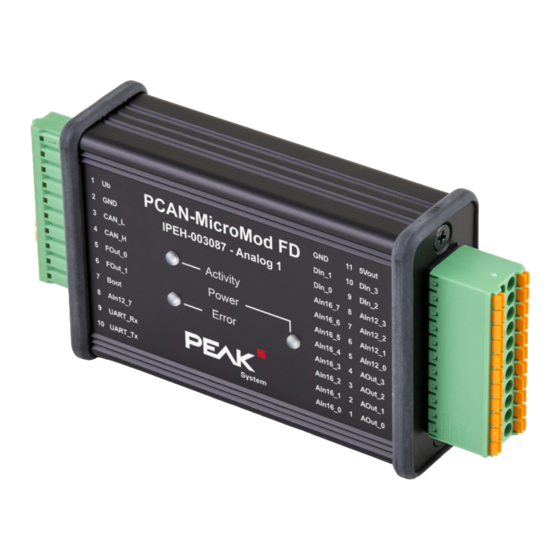
Page 7: Connectors
FMC 1,5/10-ST-3,81 22-pole, double-row, Phoenix Contact Right 3.5 mm pitch DFMC 1,5/11-ST-3,5 Top view PCAN-MicroMod FD Analog 1 with pin assignment 2.1 Basic Connectivity (left connector) Connector left 10-pole Pin Identifier Function Comment Voltage supply 8 - 30 V DC Power LED is on when supply is present. -
Page 8: I/O (Right Connector)
Corrently no use UART_Tx For the startup of the PCAN-MicroMod FD Analog 1 it is sufficient to connect a voltage source to pins 1 and 2. The configuration of the PCAN-MicroMod FD Analog 1 is done via the CAN bus being connected to pins 3 and 4. Read more in 5 Configuration Soft- ware on page 15. -
Page 9: Measuring Range Adjustment Of The Analog Inputs
±5 V ±10 V ±20 V The measuring range of the analog inputs with 12-bit resolution (AIn12) is fixed at 10 V (except AIn12_7: 30 V) and cannot be changed. 2 Connectors PCAN-MicroMod FD Analog 1 User Manual 1.2.0 © 2021 PEAK-System Technik GmbH... -
Page 10: Status Leds
Comment ation Green blinking Normal operation (1 Hz) Green faster No configuration with The PCAN-MicroMod FD is ready for receiving a confi- blinking (2 Hz) the set module ID guration with 500 kbit/s. Activity Orange quick CAN bootloader Ready for transfer of new firmware.*... -
Page 11: Optional Hardware Settings
Several MicroMod-FD-based devices are to be configured on the same bus: 4.1 Set Device ID below The PCAN-MicroMod FD Analog 1 is to be used on one end of a CAN bus that is not fully terminated (for example, when two CAN nodes are connected directly): 4.2 Activate Internal CAN Bus Termination on page 13... - Page 12 (0 to 15, with positions A to F corresponding to numbers 10 to 15). Note: A changed device ID only takes effect after the PCAN- MicroMod FD Analog 1 has been restarted. 4 Optional Hardware Settings PCAN-MicroMod FD Analog 1 User Manual 1.2.0 © 2021 PEAK-System Technik GmbH...
-
Page 13: Activate Internal Can Bus Termination
CAN-High and CAN-Low lines. If the PCAN-MicroMod FD Analog 1 is to be connected to one end of the High-speed CAN bus, the internal termination can be activated to take the termination on this side of the CAN bus. - Page 14 Do the following to activate the internal termination: 1. Set the slide switch next to the 10-pole connector J1 to the “ON” position. 4 Optional Hardware Settings PCAN-MicroMod FD Analog 1 User Manual 1.2.0 © 2021 PEAK-System Technik GmbH...
-
Page 15: Configuration Software
Windows 10, 8.1 (32/64-Bit) PC-CAN interface from PEAK-System (CAN FD capability recommended) CAN cabling between the CAN interface and the PCAN-MicroMod FD Analog 1 with proper termination (120 Ω on each end of the CAN bus) 5.2 Downloading and Installing the Configuration... - Page 16 “make changes on this computer”. 4. Follow the instructions of the installation program. You can find further information about the use of the program PCAN-MicroMod FD Configuration in the help which you can invoke in the program (for example with the |F1| key).
-
Page 17: Firmware Update
6 Firmware Update The PCAN-MicroMod FD Analog 1 (called MicroMod FD device in this chapter) can receive a firmware update via CAN. This is done with the Windows program PEAK- Flash. Go through the following sections for a firmware update. 6.1 System Requirements Firmware Update Windows 10, 8.1 (32/64-Bit) -
Page 18: Update Procedure
2. Unpack the downloaded PEAK-Flash.zip file to an arbitrary target directory on your Windows computer. The PEAK-Flash.exe file in the target directory is the executable to be used later. [Optional] On the Windows desktop, create a link to PEAK-Flash.exe for easier access to the program later. -
Page 19: Activate Flash Mode By Hardware
The MicroMod FD device is now ready for use with the new firmware. 6.4 Activate Flash Mode by Hardware If the MicroMod FD device cannot be set to Flash mode via PEAK-Flash, this can be done alternatively by hardware. Do the following to activate the flash mode by hardware: 1. -
Page 20: Technical Specifications
± 2 LSB 370 kΩ Input impedance 1 MΩ 1 MΩ 1 MΩ minimum Low-pass = 3 kHz Sample rate 1 ms (independent of CAN communication) 7 Technical Specifications PCAN-MicroMod FD Analog 1 User Manual 1.2.0 © 2021 PEAK-System Technik GmbH... - Page 21 > 5.8 V typ. (4.5 V – 7.5 V) High Switching thresholds High → < 3.5 V typ. (2.2 V – 4.5 V) Low-pass = 3 kHz 7 Technical Specifications PCAN-MicroMod FD Analog 1 User Manual 1.2.0 © 2021 PEAK-System Technik GmbH...
- Page 22 7.32 mV LSB) Input impedance 20 kΩ ± 0.2 % Measuring accuracy ± 2 LSB Low-pass = 340 Hz Sample rate 1 ms (independent of CAN communication) 7 Technical Specifications PCAN-MicroMod FD Analog 1 User Manual 1.2.0 © 2021 PEAK-System Technik GmbH...
- Page 23 Power Supply Operating voltage Ub 8 – 30 V DC, 12 V nominal Current consumption max. 100 mA, typ. 45 mA at 12 V w/o load 7 Technical Specifications PCAN-MicroMod FD Analog 1 User Manual 1.2.0 © 2021 PEAK-System Technik GmbH...
- Page 24 EU directive 2011/65/EU (RoHS 2) RoHS EU directive 2015/863/EU (amended list of restricted substances) DIN EN IEC 63000:2019-05;VDE 0042-12:2019-05 EU directive 2014/30/EU DIN EN 61326-1:2013-07;VDE 0843-20-1:2013-07 7 Technical Specifications PCAN-MicroMod FD Analog 1 User Manual 1.2.0 © 2021 PEAK-System Technik GmbH...
-
Page 25: Appendix A Ce Certificate
Appendix A CE Certificate Appendix A CE Certificate PCAN-MicroMod FD Analog 1 User Manual 1.2.0 © 2021 PEAK-System Technik GmbH... -
Page 26: Appendix B Dimension Drawings
Appendix B Dimension Drawings Dimension drawing with top view and side view. The scale of the drawings differs from an 1-to-1 representation. Appendix B Dimension Drawings PCAN-MicroMod FD Analog 1 User Manual 1.2.0 © 2021 PEAK-System Technik GmbH... -
Page 27: Appendix C Changelog User Manual
(on page 20) Input impedance AIn12_7: 20 kΩ (on page 20) No more support from PEAK-System for Windows 7 Firmware update procedure with the software tool PEAK-Flash for Windows (no longer PCAN-Flash) (on page 17) Conformity adaptation RoHS (on page 25):...
Need help?
Do you have a question about the PCAN-MicroMod FD and is the answer not in the manual?
Questions and answers