Peak PCAN-MicroMod FD User Manual
Hide thumbs
Also See for PCAN-MicroMod FD:
- User manual (42 pages) ,
- User manual (34 pages) ,
- User manual (37 pages)

Related Manuals for Peak PCAN-MicroMod FD


Summary of Contents for Peak PCAN-MicroMod FD
- Page 1 PCAN-MicroMod FD Evaluation Board User Manual User Manual 1.1.0 © 2020 PEAK-System Technik GmbH...
-
Page 2: Imprint
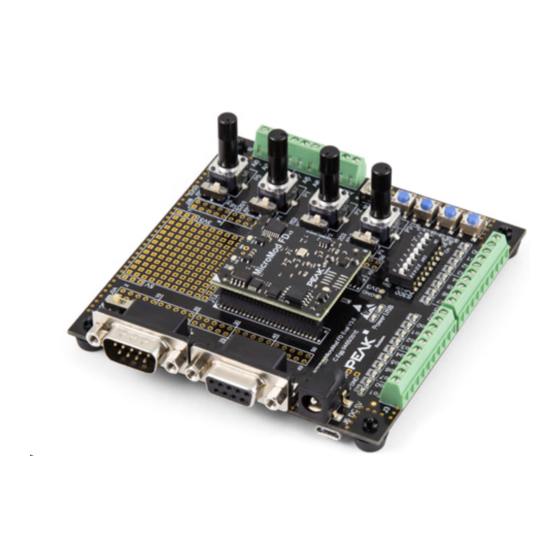
PCAN-MicroMod FD Evaluation Kit IPEH-003082 PCAN-USB FD, and terminated CAN cable The picture on the front page shows the Evaluation Board with plugged-on PCAN-MicroMod FD. Imprint PCAN® is a registered trademark of PEAK-System Technik GmbH. CANopen®, CANopen FD®, and CiA® are registered EU trademarks of CAN in Automation e.V. -
Page 3: Table Of Contents
4.1 Firmware Update via CAN Bus 4.1.1 System Requirements 4.1.2 Flash Software Preparation 4.1.3 Update Procedure 4.1.4 Activate Flash Mode by Hardware 4.2 Firmware Update via USB Connection 4.2.1 System Requirements Contents PCAN-MicroMod FD Evaluation Board User Manual 1.1.0 © 2020 PEAK-System Technik GmbH... - Page 4 4.3.2 Activating the Flash Mode 4.3.3 Uploading the Firmware 5 Technical Specifications Appendix A Dimension Drawing Appendix B Circuit Diagram Evaluation Board Schaltplan Evaluation-Board Appendix C Changelog User Manual Contents PCAN-MicroMod FD Evaluation Board User Manual 1.1.0 © 2020 PEAK-System Technik GmbH...
-
Page 5: Introduction
1 Introduction This product is an evaluation board for the PCAN-MicroMod FD and allows the concep- tion and development of own circuits with CAN connection and I/O functionality. It can also be used for training purposes for CAN and CAN FD setups. Via pick-offs, screw terminals, switches, and potentiometers, the user can access the resources of the attached PCAN-MicroMod FD and check configurations or test circuits. -
Page 6: Operation Requirements
Configuration via the CAN bus with the Windows software PCAN-MicroMod FD Configuration Firmware upload via CAN, USB, or RS-232; switchable via 3 buttons Reset button for restarting the board Voltage supply 5 V via Micro-USB or barrel connection Operating temperature range from 0 to 70 °C (32 to 158 °F) Board 102 x 100 mm with rubber feet 1.2 Operation Requirements... -
Page 7: Scope Of Supply "Kit" (Ipeh-003082)
1.4 Scope of Supply “Kit” (IPEH-003082) As above (IPEH-003081) and in addition: PC-CAN interface PCAN-USB FD (IPEH-004022) CAN cable, terminated with 2 x 120 Ω, 2 m (IPEK-003001) 1 Introduction PCAN-MicroMod FD Evaluation Board User Manual 1.1.0 © 2020 PEAK-System Technik GmbH... -
Page 8: Setting Up The Evaluation Kit For Operation
Evaluation Board and either a USB port on the computer or a power supply unit. 5. Under Windows, install the configuration program PCAN-MicroMod FD Config- uration from the supplied data carrier (Tools section). 2 Setting Up the Evaluation Kit for Operation PCAN-MicroMod FD Evaluation Board... - Page 9 6. Start PCAN-MicroMod FD Configuration, create a configuration, and finally send this configuration to the PCAN-MicroMod FD (see program help). You can now work with signals at the inputs and outputs as defined in the config- uration and use the CAN monitor PCAN-View on the PC to monitor and send CAN messages.
-
Page 10: Components Of The Evaluation Board
MicroMod FD (upper left corner) and on the Evaluation Board. These markings must align. Socket for the PCAN-MicroMod FD 3 Components of the Evaluation Board PCAN-MicroMod FD Evaluation Board User Manual 1.1.0 © 2020 PEAK-System Technik GmbH... - Page 11 MicroMod FD) each pin of the plugged-on MicroMod FD can be accessed directly. Test point fields J2A and J2B for all pins of the PCAN-MicroMod FD 3 Components of the Evaluation Board PCAN-MicroMod FD Evaluation Board User Manual 1.1.0 © 2020 PEAK-System Technik GmbH...
-
Page 12: Power Supply (J6, J7)
Diameter of barrel connector: a = 5.5 mm, b = 2.5 mm; minimum length: 11 mm The Power LED indicates that the Evaluation Board is supplied. 3 Components of the Evaluation Board PCAN-MicroMod FD Evaluation Board User Manual 1.1.0 © 2020 PEAK-System Technik GmbH... -
Page 13: Usb Connector (J7)
The 9-pin D-Sub male connector J4 is used for a CAN connection, positioned on the upper left of the Evaluation Board. The pin assignment of the CAN connector corres- ponds to the specification CiA® 303-1. 3 Components of the Evaluation Board PCAN-MicroMod FD Evaluation Board User Manual 1.1.0 © 2020 PEAK-System Technik GmbH... - Page 14 Board. For this purpose, switch S3 (next to the CAN connector) must be set to the On position. For better electromagnetic compatibility, a split termination is implemented. 3 Components of the Evaluation Board PCAN-MicroMod FD Evaluation Board User Manual 1.1.0 © 2020 PEAK-System Technik GmbH...
-
Page 15: Analog Inputs (J8) And Potentiometers
The Evaluation Board has 4 potentiometers (P0 to P3) which can be used for simu- lating input signals. Using the switches S200 to S203, the analog inputs Ai0 to Ai3 are 3 Components of the Evaluation Board PCAN-MicroMod FD Evaluation Board User Manual 1.1.0 © 2020 PEAK-System Technik GmbH... -
Page 16: Digital Inputs (J9)
The Evaluation Board has 8 digital inputs with TTL levels (Di0 – Di7). The corres- ponding connector is J9 (screw terminals on the lower right). 3 Components of the Evaluation Board PCAN-MicroMod FD Evaluation Board User Manual 1.1.0 © 2020 PEAK-System Technik GmbH... - Page 17 Signals that directly lead to the MicroMod FD can be accessed on the following points of the field J2B: Pin on J2B Processed input signal (inverted) 3 Components of the Evaluation Board PCAN-MicroMod FD Evaluation Board User Manual 1.1.0 © 2020 PEAK-System Technik GmbH...
-
Page 18: Digital And Frequency Outputs (J3)
CAN bus when configurations are sent and received. The rotary switch can be used to set a module number from 0 to 15 (hexadecimal 0 to F). 3 Components of the Evaluation Board PCAN-MicroMod FD Evaluation Board User Manual 1.1.0 © 2020 PEAK-System Technik GmbH... -
Page 19: Rs-232 Connector (J5)
3.9 RS-232 Connector (J5) The RS-232 connector can alternatively be used for transferring firmware to the PCAN-MicroMod FD. You need a suitable flashing tool, e.g. Flash Magic (www.flashmagictool.com), and a firmware file in hex format. 3 Components of the Evaluation Board PCAN-MicroMod FD Evaluation Board... -
Page 20: Push Buttons For Reset And Flash Mode
The four blue push buttons located on the lower right side have the following func- tions: Push button Function Reset Reset of the PCAN-MicroMod FD, restart of the firmware Boot Flash mode for a firmware update via CAN Flash mode for a firmware update via USB... - Page 21 Blue push buttons More information about the procedure for firmware updates is available in 4 Firm- ware Update of the PCAN-MicroMod FD on the next page. 3 Components of the Evaluation Board PCAN-MicroMod FD Evaluation Board User Manual 1.1.0 © 2020 PEAK-System Technik GmbH...
-
Page 22: Firmware Update Of The Pcan-Micromod Fd
4 Firmware Update of the PCAN-MicroMod FD The PCAN-MicroMod FD can be equipped with new firmware in three different ways: via CAN bus (with the Windows program PEAK-Flash) via USB connection (easiest way on the Evaluation Board) via serial RS-232 interface (only for special purposes) The following sections describe the procedures. -
Page 23: Update Procedure
Unpack the downloaded PEAK-Flash.zip file to an arbitrary target directory on your Windows computer or copy the PEAK-Flash directory from the data carrier. The PEAK-Flash.exe file in the target directory is the executable to be used later. 4.1.3 Update Procedure 1. -
Page 24: Activate Flash Mode By Hardware
The PCAN MicroMod FD is now ready for use with the new firmware. 4.1.4 Activate Flash Mode by Hardware If the PCAN MicroMod FD cannot be set to Flash mode via PEAK-Flash, this can be done alternatively by hardware. Do the following to set the PCAN-MicroMod FD to flash mode for CAN: 1. -
Page 25: Activating The Flash Mode
5. Disconnect the USB cable between the PC and the Evaluation Board. 6. Restart the MicroMod FD (for example with the blue Reset button). 4 Firmware Update of the PCAN-MicroMod FD PCAN-MicroMod FD Evaluation Board User Manual 1.1.0 © 2020 PEAK-System Technik GmbH... -
Page 26: Firmware Update Via Serial Rs-232 Interface
(e.g. the CAN bootloader in the address range 0x0000-0x7fff). 4 Firmware Update of the PCAN-MicroMod FD PCAN-MicroMod FD Evaluation Board User Manual 1.1.0 © 2020 PEAK-System Technik GmbH... - Page 27 8. When the update process is Finished (corresponding message), quit the Flash Magic program and restart the MicroMod FD (for example with the blue Reset button). 4 Firmware Update of the PCAN-MicroMod FD PCAN-MicroMod FD Evaluation Board User Manual 1.1.0 © 2020 PEAK-System Technik GmbH...
-
Page 28: Technical Specifications
5 Technical Specifications This chapter covers the technical specifications of the PCAN-MicroMod FD Evaluation Board with plugged-on PCAN-MicroMod FD. Further data about the PCAN-MicroMod FD can be found in the separate manual for the module. Information about the PC- CAN interface PCAN-USB FD from the Kit is available in the corresponding separate manual. - Page 29 Measures 102 x 38 x 100 mm (W x H x D, H incl. potentiometer pegs) Size of circuit board See also Appendix A Dimension Drawing on page 30 83 g without PCAN-MicroMod FD Weight 92 g with PCAN-MicroMod FD Environment Operating temperature 0 –...
-
Page 30: Appendix A Dimension Drawing
Appendix A Dimension Drawing The scale of the drawing differs from an 1-to-1 representation. Appendix A Dimension Drawing PCAN-MicroMod FD Evaluation Board User Manual 1.1.0 © 2020 PEAK-System Technik GmbH... -
Page 31: Appendix B Circuit Diagram Evaluation Board
The following pages show the electronic circuit diagram of the Evaluation Board for the PCAN-MicroMod FD. For example, it can be used as a reference for your own MicroMod FD circuitry. Appendix B Circuit Diagram Evaluation Board PCAN-MicroMod FD Evaluation Board User Manual 1.1.0 © 2020 PEAK-System Technik GmbH... -
Page 32: Schaltplan Evaluation-Board
I_DIn 2 I_DIn 3 MicroMod FD I_DIn Fiducial Fiducial Fiducial Fiducial Fiducial Fiducial I_DIn 4 I_DIn 5 C PEAK-System Technik GmbH I_DIn 6 BOM2 BOM3 BOM4 I_DIn 7 AC to DC Titel: USB to µ-USB 230V -> 5V MicroModFD Eval µ-USB-Cable... - Page 33 VIn Max = 5V + 0.36V + 0.105V + 0.01414V VIn Max =5.47V VIn min = 3.3V +Vfmax + U100 Vdropout max + U101 Vdropout max VIn min = 3.3V +0.42V+0.2V+0.302V VIn min = 4.22V C PEAK-System Technik GmbH Titel: MicroModFD Eval Blatt: PowerSupply PEAK-System Technik GmbH Otto-Röhm-Str.
- Page 34 C214 R223 100nF C215 S203 AGND 100nF JS102011JCQN SPDT AGND AGND Vref Vref AGND AGND C PEAK-System Technik GmbH Titel: MicroModFD Eval Blatt: Analog Input PEAK-System Technik GmbH Otto-Röhm-Str. 69 Auftraggeber: Version: D-64293 Darmstadt Variante: Entwickler: C.Eggers PEAK-System Technik GmbH...
- Page 35 R326 U300D R327 U301D R328 I_Din-3 Din-3 R329 I_Din-7 Din-7 R330 R331 inerverted input signal C PEAK-System Technik GmbH HEF40106BT C312 C313 HEF40106BT inerverted input signal C314 C315 Titel: MicroModFD Eval Shield Shield Blatt: Digital Input PEAK-System Technik GmbH Otto-Röhm-Str.
- Page 36 U404B Fout 0 O_Fout_0 R405 R410 GND Out D405 PowerGND SN74LV1T34DCKR std gn AUIPS2052GTR R411 PowerGND C PEAK-System Technik GmbH Titel: MicroModFD Eval Blatt: Digital Output PEAK-System Technik GmbH Otto-Röhm-Str. 69 Auftraggeber: Version: D-64293 Darmstadt Variante: Entwickler: C.Eggers PEAK-System Technik GmbH...
- Page 37 Filter uSD_Detect Filter uSD Detect Dat0 Filter Dat1 uSD_Kyocera C500 uSD Kartenhalter Kyocera 5138 Farnell 213-4442 1µF alternativ: Mouser 571-2041021-4 C PEAK-System Technik GmbH Titel: MicroModFD Eval Blatt: SD_Card PEAK-System Technik GmbH Otto-Röhm-Str. 69 Auftraggeber: Version: D-64293 Darmstadt Variante: Entwickler: C.Eggers...
- Page 38 D601 SR05-02CTG diff diff L600 USB_N USB1_N USB D- USB_P USB1_P USB D+ ICM1206ER900M C PEAK-System Technik GmbH Titel: MicroModFD Eval Blatt: USB Port PEAK-System Technik GmbH Otto-Röhm-Str. 69 Auftraggeber: Version: D-64293 Darmstadt Variante: Entwickler: C.Eggers PEAK-System Technik GmbH...
-
Page 39: Appendix C Changelog User Manual
Appendix C Changelog User Manual This section lists the major changes in the recent User Manual releases. 1.1.0 Firmware update via CAN: PEAK-Flash replaces PCAN-Flash, thereby changed procedure (on page 22) 1.0.0 First edition Appendix C Changelog User Manual PCAN-MicroMod FD Evaluation Board User Manual 1.1.0...
Need help?
Do you have a question about the PCAN-MicroMod FD and is the answer not in the manual?
Questions and answers