Advertisement
Quick Links
Advertisement

Related Manuals for Peak PCAN-MicroMod FD Analog 1


Summary of Contents for Peak PCAN-MicroMod FD Analog 1
- Page 1 PCAN-MicroMod FD Analog 1 User Manual User Manual 1.3.0 © 2024 PEAK-System Technik GmbH...
- Page 2 Configuration software for Windows Imprint PCAN® is a registered trademark of PEAK-System Technik GmbH. CANopen®, CANopen FD®, and CiA® are registered EU trademarks of CAN in Automation e.V. Arm and Cortex are registered trademarks of Arm Limited (or its subsidiaries) in the United States and/or elsewhere.
- Page 3 4.1 Requirements for Transferring a Configuration via CAN 4.2 Installing the Configuration Software 4.3 Creating a Configuration 4.4 Transferring a Configuration 5 Optional Hardware Settings 5.1 Set Device ID Contents PCAN-MicroMod FD Analog 1 User Manual 1.3.0 © 2024 PEAK-System Technik GmbH...
- Page 4 6 Firmware Upload 6.1 System Requirements 6.2 Firmware Transfer 7 Creating Custom Firmware 8 Technical Specifications Appendix A CE Certificate Appendix B UKCA Certificate Appendix C Dimension Drawings Contents PCAN-MicroMod FD Analog 1 User Manual 1.3.0 © 2024 PEAK-System Technik GmbH...
- Page 5 CAN FD bit rates for the data field (max. 64 bytes) from 20 kbit/s up to 10 Mbit/s CAN termination switchable 1 analog input for voltage monitoring up to 30 V, resolution 12 bits 1 Introduction PCAN-MicroMod FD Analog 1 User Manual 1.3.0 © 2024 PEAK-System Technik GmbH...
- Page 6 Power supply in the range of 8 to 30 V DC (connection via 10-pole spring terminal strip) For transfer of the configuration and for a firmware update (both via CAN): Windows 11 (x64/ARM64), 10 (x64) PC-CAN interface from PEAK-System (CAN FD capability recommended) 1 Introduction PCAN-MicroMod FD Analog 1 User Manual 1.3.0...
- Page 7 Note: The transfer of the configuration and a firmware update are done with CAN 2.0 messages. For this reason, all PC-CAN interfaces from PEAK-System work in principle for this purpose. We recommend the use of CAN-FD-capable interfaces in order to activate the necessary operation modes of the PCAN-MicroMod FD Analog 1 also during CAN...
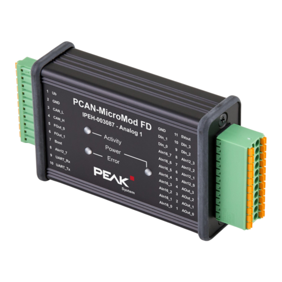
- Page 8 Right 22-pole, double-row, Phoenix Contact 3.5 mm pitch DFMC 1,5/11 - ST - 3,5 Top view PCAN-MicroMod FD Analog 1 with pin assignment 2.1 Basic Connectivity (left connector) Connector left 10-pole 2 Connectors PCAN-MicroMod FD Analog 1 User Manual 1.3.0 © 2024 PEAK-System Technik GmbH...
- Page 9 CAN bus being connected to pins 3 and 4. Read more in 4 Configuration on page 18. 2.2 I/O (right connector) Right connector 2 x 11 terminals 2 Connectors PCAN-MicroMod FD Analog 1 User Manual 1.3.0 © 2024 PEAK-System Technik GmbH...
- Page 10 ±5 V ±10 V ±20 V The measuring range of the analog inputs with 12-bit resolution (AIn12) is fixed at 10 V (except AIn12_7: 30 V) and cannot be changed. 2 Connectors PCAN-MicroMod FD Analog 1 User Manual 1.3.0 © 2024 PEAK-System Technik GmbH...
- Page 11 CANopen Custom firmware CAN FD CANopen FD ■ ■ ■ PCAN-MicroMod FD Evaluation ■ ❒ ■ PCAN-MicroMod FD Analog 1 ■ ❒ ■ PCAN-MicroMod FD Digital 1/2 ■ PCAN-MicroMod FD ECU — — ■ ■ PCAN-MicroMod FD DR CANopen Digital 1 —...
- Page 12 5. On the Bit Timing tab select the Nominal Bit Rate currently used by the PCAN- MicroMod FD Analog 1, with CAN FD additionally the Data Bit Rate. 6. Confirm with Connect. 3 Operation PCAN-MicroMod FD Analog 1 User Manual 1.3.0 © 2024 PEAK-System Technik GmbH...
- Page 13 Done via CAN bus with the Windows software PCAN-MicroMod FD Configuration Manal definition of the transmit and receive CAN messages Mapping of I/O signals to the CAN messages 3 Operation PCAN-MicroMod FD Analog 1 User Manual 1.3.0 © 2024 PEAK-System Technik GmbH...
- Page 14 The PCAN-MicroMod FD Evaluation Board can be freely programmed with help of our cost-free development package for ARM-based products. The included programming examples make it easier to start implementing own solutions. See also: 7 Creating Custom Firmware on page 28 3 Operation PCAN-MicroMod FD Analog 1 User Manual 1.3.0 © 2024 PEAK-System Technik GmbH...
- Page 15 3.3 Status LEDs LEDs on the PCAN-MicroMod FD Analog 1 The description of the LED status displays refers to the CAN/CAN FD operating mode of the standard firmware. 3 Operation PCAN-MicroMod FD Analog 1 User Manual 1.3.0 © 2024 PEAK-System Technik GmbH...
- Page 16 3.4 Reserved CAN ID 7E7h For configuring a product of the PCAN-MicroMod FD series and for firmware upload, the 11-bit CAN ID 7E7h is used. The corresponding programs from PEAK-System exchanges data with the module via the CAN bus using this CAN ID. When designing your CAN network, make sure not to use the CAN ID 7E7h in any way.
- Page 17 Hysteresis, Limit, RS Flip Flop, Switch Delay, Greater Than. Find more details about the functionality and the application of the services in the help of the PCAN-MicroMod FD Configuration program. 3 Operation PCAN-MicroMod FD Analog 1 User Manual 1.3.0 © 2024 PEAK-System Technik GmbH...
- Page 18 4.2 Installing the Configuration Software Install PCAN-MicroMod FD Configuration on your computer as follows: 1. Download the configuration software PCAN-MicroMod FD Configuration. Download page: www.peak-system.com/quick/DL-Software-E 2. Unpack the file. 4 Configuration PCAN-MicroMod FD Analog 1 User Manual 1.3.0 © 2024 PEAK-System Technik GmbH...
- Page 19 5. Indicate the Bit Rate of the CAN bus on which the PCAN-MicroMod FD Analog 1 will later be used. 6. Indicate the previously set Module ID of your PCAN-MicroMod FD Analog 1. 7. Confirm your settings with OK. 8. Save your configuration. 4 Configuration PCAN-MicroMod FD Analog 1 User Manual 1.3.0 © 2024 PEAK-System Technik GmbH...
- Page 20 2. Connect the PCAN-MicroMod FD Analog 1 to the CAN interface via a terminated CAN bus. 3. In PCAN-MicroMod FD Configuration, click on Connect to establish a connection to the CAN bus. The Connect window appears. 4 Configuration PCAN-MicroMod FD Analog 1 User Manual 1.3.0 © 2024 PEAK-System Technik GmbH...
- Page 21 2. Select your PCAN-MicroMod FD Analog 1 and click Send. After a successful transfer of the configuration, you can use your PCAN-MicroMod FD Analog 1 with the new configuration. 4 Configuration PCAN-MicroMod FD Analog 1 User Manual 1.3.0 © 2024 PEAK-System Technik GmbH...
- Page 22 To open the casing and remove the circuit board: Attention! Electrostatic discharge (ESD) can damage or destroy components on the circuit board. Take precautions to avoid ESD when handling the circuit board. 5 Optional Hardware Settings PCAN-MicroMod FD Analog 1 User Manual 1.3.0 © 2024 PEAK-System Technik GmbH...
- Page 23 CAN bus. This is done with a switch on the board. For this you have to remove it from the casing. 5 Optional Hardware Settings PCAN-MicroMod FD Analog 1 User Manual 1.3.0 © 2024 PEAK-System Technik GmbH...
- Page 24 4. For later assembly, proceed in reverse order. Do the following to activate the internal termination: 1. Set the slide switch next to the 10-pole connector J1 to the “ON” position. 5 Optional Hardware Settings PCAN-MicroMod FD Analog 1 User Manual 1.3.0 © 2024 PEAK-System Technik GmbH...
- Page 25 6 Firmware Upload The microcontroller in the PCAN-MicroMod FD Analog 1 is equipped with new firmware via CAN. The upload is done with the Windows program PEAK-Flash. 6.1 System Requirements CAN interface of the PCAN series for the computer, e.g. PCAN-USB FD CAN cabling between the CAN interface and the PCAN-MicroMod FD Analog 1 with...
- Page 26 2. If PEAK-Flash is not yet installed on your computer, download the installation package from the following web page and run the contained setup program: www.peak-system.com/quick/DL-Software-E Tip: [STD] With the current installation package for PEAK-Flash, you also receive the latest version of the standard firmware for your device.
- Page 27 16. [STD] The previous configuration on the PCAN-MicroMod FD Analog 1 may no longer be valid, so you may have to transfer the configuration to the device again before it will work normally. 6 Firmware Upload PCAN-MicroMod FD Analog 1 User Manual 1.3.0 © 2024 PEAK-System Technik GmbH...
- Page 28 7 Creating Custom Firmware Using the PEAK-DevPack development package and the cost-free Visual Studio Code development environment (IDE) from Microsoft, you can create your own application-specific firmware for programmable hardware products from PEAK- System. Downloads PEAK-DevPack (direct download): www.peak-system.com/quick/DLP-DevPack Visual Studio Code (homepage): code.visualstudio.com...
- Page 29 Setup of the Environment and Firmware Creation 1. Create a folder on your PC. We recommend to use a local drive. 2. Unzip the PEAK-DevPack.zip development package completely into your folder. No installation is required. 3. Run the SetPath_for_VSCode.vbs script.
- Page 30 ± 2 LSB Input impedance 1 MΩ 1 MΩ 1 MΩ 370 kΩ minimum Low-pass = 3 kHz Sample rate 1 ms (independent of CAN communication) 8 Technical Specifications PCAN-MicroMod FD Analog 1 User Manual 1.3.0 © 2024 PEAK-System Technik GmbH...
- Page 31 FOut_0, FOut_1 Maximum frequency 20 kHz Output driver Low-side switch Infineon AUIPS2052G Voltage proof 55 V Output current 0.9 A (constant current) Protection Short circuit protection 8 Technical Specifications PCAN-MicroMod FD Analog 1 User Manual 1.3.0 © 2024 PEAK-System Technik GmbH...
- Page 32 (120 Ω between CAN-High and CAN - Low) Termination Electric strength ±20 V CAN ID reserved for 7E7h configuration transfer CAN Bootloader Connector Boot Activation High-active (switching threshold 1.7 V) during reset 8 Technical Specifications PCAN-MicroMod FD Analog 1 User Manual 1.3.0 © 2024 PEAK-System Technik GmbH...
- Page 33 −40 to +85 °C (−40 to +185 °F) Temperature for storage −40 to +100 °C (−40 to +212 °F) and transport Relative humidity 15 to 90 %, not condensing Ingress protection IP20 (IEC 60529) 8 Technical Specifications PCAN-MicroMod FD Analog 1 User Manual 1.3.0 © 2024 PEAK-System Technik GmbH...
- Page 34 Conformity EU directive 2011/65/EU (RoHS 2) + EU directive 2015/863/EU RoHS (amended list of restricted substances) DIN EN IEC 63000:2019-05 EU directive 2014/30/EU DIN EN 61326-1:2022-11 8 Technical Specifications PCAN-MicroMod FD Analog 1 User Manual 1.3.0 © 2024 PEAK-System Technik GmbH...
- Page 35 Appendix A CE Certificate EU Declaration of Conformity This declaration applies to the following product: PCAN-MicroMod FD Analog 1 Product name: IPEH-003087 Item number(s): Manufacturer: PEAK-System Technik GmbH Leydheckerstraße 10 64293 Darmstadt Germany We declare under our sole responsibility that the mentioned product is in...
- Page 36 Appendix B UKCA Certificate UK Declaration of Conformity This declaration applies to the following product: PCAN-MicroMod FD Analog 1 Product name: IPEH-003087 Item number(s): Manufacturer: UK authorized representative: PEAK-System Technik GmbH Control Technologies UK Ltd Leydheckerstraße 10 Unit 1, Stoke Mill,...
- Page 37 Appendix C Dimension Drawings Dimension drawing with top view and side view. The scale of the drawings differs from an 1-to-1 representation. Appendix C Dimension Drawings PCAN-MicroMod FD Analog 1 User Manual 1.3.0 © 2024 PEAK-System Technik GmbH...
Need help?
Do you have a question about the PCAN-MicroMod FD Analog 1 and is the answer not in the manual?
Questions and answers