Peak PCAN-MicroMod FD User Manual
Hide thumbs
Also See for PCAN-MicroMod FD:
- User manual (42 pages) ,
- User manual (37 pages) ,
- User manual (39 pages)
Table of Contents
Advertisement
Quick Links
Advertisement
Table of Contents

Related Manuals for Peak PCAN-MicroMod FD


Summary of Contents for Peak PCAN-MicroMod FD
- Page 1 PCAN-MicroMod FD User Manual User Manual 1.1.1 © 2020 PEAK-System Technik GmbH...
-
Page 2: Imprint
IPEH-003080 Imprint PCAN® is a registered trademark of PEAK-System Technik GmbH. CANopen®, CANopen FD®, and CiA® are registered EU trademarks of CAN in Automation e.V. Arm and Cortex are registered trademarks of Arm Limited (or its subsidiaries) in the United States and/or elsewhere. -
Page 3: Table Of Contents
Appendix B Dimension Drawings Appendix C CPU Adapter for 2.54 mm Pitch C.1 Description CPU Adapter C.2 Pin Assignment CPU Adapter C.3 Dimension Drawings CPU Adapter Appendix D Minimum Circuitry PCAN-MicroMod-FD_MinimumCircuitryDiagram Contents PCAN-MicroMod FD User Manual 1.1.1 © 2020 PEAK-System Technik GmbH... - Page 4 Appendix E Changelog User Manual Contents PCAN-MicroMod FD User Manual 1.1.1 © 2020 PEAK-System Technik GmbH...
-
Page 5: Introduction
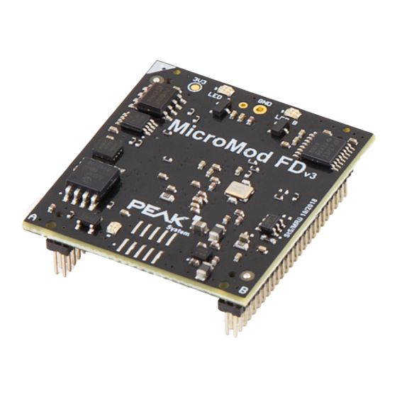
1 Introduction The PCAN-MicroMod FD is a small plug-in board with CAN and CAN FD connection on the one side and various physical inputs and outputs on the other side. The logical linking of both sides is done by the microcontroller NXP LPC54618. With the MicroMod FD, electronics developers can easily integrate I/O functionality with CAN connection into their project. -
Page 6: Operation Requirements
Extended operating temperature range from −40 to 85 °C (−40 to 185 °F) 1.2 Operation Requirements Board with socket strips or hole grid for mounting the PCAN-MicroMod FD (Evalu- ation Board, motherboard from PEAK-System or self-development), see also Appendix B Dimension Drawings on page 24. -
Page 7: Scope Of Supply
1.3 Scope of Supply PCAN-MicroMod FD plug-in board Configuration software for Windows Manual in PDF format Optional: Pin adapter for 100 mil pitch 1 Introduction PCAN-MicroMod FD User Manual 1.1.1 © 2020 PEAK-System Technik GmbH... -
Page 8: Electrical Connection
2.1 Connectors The PCAN-MicroMod FD has two double pin rows (A, B) with 50 pins each (first column in the following tables). Thus, the MicroMod FD can be plugged onto boards with matching socket strips (50-mil/1.27-mm grid, see also Appendix B Dimension Draw- ings on page 24). - Page 9 Dout-7 CAN-H High-speed CAN ISO 11898-2: differential signal High CAN-L High-speed CAN ISO 11898-2: differential signal Low Reset-in# Module reset, Low-active, internal pull-up 10 kΩ to 3.3 V Ground 2 Electrical Connection PCAN-MicroMod FD User Manual 1.1.1 © 2020 PEAK-System Technik GmbH...
- Page 10 Connection to alternative, external CAN transceiver (is enabled by pin A19) Ext-CAN_TxD Ext-CAN_RxD Ground Pin MMFD Designation Function Ground FC0_V24_TxD FC0_V24_RxD Serial RS-232 interface for firmware updates FC0_V24_RTS FC0_V24_CTS 2 Electrical Connection PCAN-MicroMod FD User Manual 1.1.1 © 2020 PEAK-System Technik GmbH...
- Page 11 USB bootloader is started if put on ground during start-up Boot-USB# (USB pins: B23, B25, B27) Fout-0 Frequency outputs 0 and 1, level 3.3 V Fout-1 Reserved Reserved Reserved Reserved 2 Electrical Connection PCAN-MicroMod FD User Manual 1.1.1 © 2020 PEAK-System Technik GmbH...
-
Page 12: Circuitry
3V3in Supply voltage input 3.3 V DC, 100mA (connected to B47) Ground 2.2 Circuitry For the basic operation of the PCAN-MicroMod FD, a minimal circuitry with the following components is required: Voltage supply 3.3 V DC CAN connection (CAN-High, CAN-Low) Pull-down for module ID inputs... - Page 13 A comprehensive circuit example can be found in the circuit diagram for the separ- ately available Evaluation Board. The circuit diagram is part of the corresponding user manual PCAN-MicroMod FD Evaluation Board. Tip: When designing the circuitry for the PCAN-MicroMod FD, also observe the protection against overvoltage and reverse polarity at inputs.
-
Page 14: Operation
Ready for transfer. New firmware can be transferred to Orange quick blinking CAN Bootloader the PCAN-MicroMod FD via CAN bus using the Windows (4 Hz) program PEAK-Flash. The PCAN-MicroMod FD does not have a valid firm- Red on Firmware error ware. -
Page 15: Reserved Can Id 7E7H
3.2 Reserved CAN ID 7E7h To configure the PCAN-MicroMod FD, the 11-bit CAN ID 7E7h is used. Accordingly, the PCAN-MicroMod FD Configuration program exchanges data with the module via the CAN bus. When designing your CAN network, make sure not to use the CAN ID 7E7h in any way. - Page 16 Signal. Excerpt from the collection: Mult, Mod, And, Hysteresis, Limit, RS Flip Flop, Switch Delay, Greater Than. Find more details about the functionality and the application of the services in the help of the PCAN-MicroMod FD Configuration program. 3 Operation PCAN-MicroMod FD User Manual 1.1.1...
-
Page 17: Configuration Program
Windows 10, 8.1 (32/64-bit) PC-CAN interface from PEAK-System, e.g. PCAN-USB FD CAN bus connection between the PCAN-MicroMod FD and the CAN interface of the On a computer without PCAN environment, you can create and edit a configuration with the program and transfer the configuration later to the MicroMod FD using another computer with PC CAN interface. - Page 18 3. In the list, find the PCAN-MicroMod FD Configuration entry and click on Install. 4. Follow the instructions of the installation program. Retrieve further information about the use of PCAN-MicroMod FD Configuration in the provided help that you can reach via the program (e.g. with the |F1| key).
-
Page 19: Firmware Update
* Must be connected to ground during switch-on. Tip: In order to update the firmware, we recommend the use of the Evaluation Board for the PCAN-MicroMod FD (IPEH- 003081 or kit IPEH-003082). This simplifies the connection of the cabling on the one hand and the setting of the flash mode on the other hand. -
Page 20: Technical Specifications
ISO 11898-2, CAN 2.0 A/B and CAN FD Transceiver Microchip MCP2558FD Nominal bitrates 20 kbit/s – 1 Mbit/s CAN FD data bitrates 20 kbit/s – 10 Mbit/s Galvanic isolation none Termination none 6 Technical Specifications PCAN-MicroMod FD User Manual 1.1.1 © 2020 PEAK-System Technik GmbH... - Page 21 Additional Data Channels For firmware update, only via separately available Evaluation Board For firmware update, only via separately available Evaluation Board and RS-232 with separate flash software 6 Technical Specifications PCAN-MicroMod FD User Manual 1.1.1 © 2020 PEAK-System Technik GmbH...
- Page 22 Conformity EU directive 2011/65/EU (RoHS 2) RoHS EU directive 2015/863/EU (revised list of restricted substances) DIN EN IEC 63000:2019-05;VDE 0042-12:2019-05 EU directive 2014/30/EU DIN EN 61326-1:2013-07;VDE 0843-20-1:2013-07 6 Technical Specifications PCAN-MicroMod FD User Manual 1.1.1 © 2020 PEAK-System Technik GmbH...
-
Page 23: Appendix A Ce Certificate
Appendix A CE Certificate Appendix A CE Certificate PCAN-MicroMod FD User Manual 1.1.1 © 2020 PEAK-System Technik GmbH... -
Page 24: Appendix B Dimension Drawings
The scale of the drawings differs from an 1-to-1 representation. Pitch of connection pins: 50 mil ≙ 1.27 mm Lower figure: example for plug-in positioning on a motherboard. Possible socket strip (2 pieces) as coun- terpart to the PCAN-MicroMod FD: Amtek 5PS3MSA44-225GONPNRU-00 Appendix B Dimension Drawings PCAN-MicroMod FD User Manual 1.1.1... -
Page 25: Appendix C Cpu Adapter For 2.54 Mm Pitch
Pitch C.1 Description CPU Adapter The pin strips of the PCAN-MicroMod FD have a 50 mil/1.27 mm pitch. On request, PEAK-System offers an adapter for circuit boards with 100-mil/2.54-mm grid. The CPU adapter has a circuit board with two socket strips for holding the PCAN- MicroMod FD and four pin strips with 100-mil-/2.54-mm pitch. -
Page 26: Pin Assignment Cpu Adapter
LED-A_green Open-drain outputs for external status LEDs LED-B_red LED-B_green FC1_I2C-SDA I²C 1: identification of the motherboard type via external EEPROM FC1_I2C-SCL Reserved Reserved Appendix C CPU Adapter for 2.54 mm Pitch PCAN-MicroMod FD User Manual 1.1.1 © 2020 PEAK-System Technik GmbH... - Page 27 Module reset, Low-active, internal pull-up 10 kΩ to 3.3 V Ground Pin MMFD Designation Function Adapter Ground Reserved Reserved Reserved Reserved Reserved Reserved Reserved Reserved Reserved Reserved Reserved Appendix C CPU Adapter for 2.54 mm Pitch PCAN-MicroMod FD User Manual 1.1.1 © 2020 PEAK-System Technik GmbH...
- Page 28 - Pin open (internal pull-up): 0 ID_Bit-2# - Pin on ground: 1 ID_Bit-3# Vbus USB1_P Connection to a USB host (PC) for firmware update USB1_N Reserved Appendix C CPU Adapter for 2.54 mm Pitch PCAN-MicroMod FD User Manual 1.1.1 © 2020 PEAK-System Technik GmbH...
- Page 29 Boot-USB# (USB pins: B23, B25, B27) Fout-0 Frequency outputs 0 and 1, level 3.3 V Fout-1 Reserved Reserved Reserved Reserved Reserved Reserved Reserved Reserved Appendix C CPU Adapter for 2.54 mm Pitch PCAN-MicroMod FD User Manual 1.1.1 © 2020 PEAK-System Technik GmbH...
-
Page 30: Dimension Drawings Cpu Adapter
3V3in Supply voltage input 3.3 V DC, 100mA (connected to B47) Ground C.3 Dimension Drawings CPU Adapter Dimensions of the CPU adapter (top view) Appendix C CPU Adapter for 2.54 mm Pitch PCAN-MicroMod FD User Manual 1.1.1 © 2020 PEAK-System Technik GmbH... - Page 31 Height dimension of the CPU adapter including PCAN-MicroMod FD Appendix C CPU Adapter for 2.54 mm Pitch PCAN-MicroMod FD User Manual 1.1.1 © 2020 PEAK-System Technik GmbH...
-
Page 32: Appendix D Minimum Circuitry
The following diagram shows the minimum circuitry required to operate the PCAN- MicroMod FD. Tip: The download area for the PCAN-MicroMod FD on our website contains additional library files (Altium Designer file formats) that can be used for simplified integration in own circuit diagrams with the MicroMod FD. -
Page 33: Pcan-Micromod-Fd_Minimumcircuitrydiagram
Din5 Din 5 Vref In Din6 Din 6/Pint 6 Din7 Din 7/Pint 7 MicroMod_FD B F HDR 25x2 1.27mm C PEAK-System Technik GmbH Title: PCAN-MicroMod-FD Minimum Circuitry Sheet: Minimum Circuitry Overview PEAK-System Technik GmbH Otto-Röhm-Str. 69 Customer: Version: D-64293 Darmstadt... - Page 34 Diagram for minimum circuitry contains more explaining captions (on page 32) LED B of the MicroMod FD indicates invalid configuration with alternating red-green blinking (since firmware version 1.9.7, was quick green blinking before) (on page 14) Appendix E Changelog User Manual PCAN-MicroMod FD User Manual 1.1.1 © 2020 PEAK-System Technik GmbH...
Need help?
Do you have a question about the PCAN-MicroMod FD and is the answer not in the manual?
Questions and answers