Table of Contents
Advertisement
Quick Links
Advertisement
Table of Contents

Related Manuals for Peak PCAN-PCI Express


Summary of Contents for Peak PCAN-PCI Express
- Page 1 PCAN-PCI Express User Manual User Manual 4.0.0 © 2022 PEAK-System Technik GmbH...
-
Page 2: Imprint
Imprint PCAN is a registered trademark of PEAK-System Technik GmbH. CiA® is a registered community trade mark of CAN in Automation e.V. All other product names in this document may be the trademarks or registered trademarks of their respective companies. -
Page 3: Table Of Contents
1.3 Scope of Supply 2 Setting 2.1 Voltage Supply of External Devices 3 Installation 3.1 Install Device Driver Setup 3.2 Installing the PCAN-PCI Express card 3.3 Check Operational Readiness 4 Connecting the CAN Bus 4.1 Connection over D-Sub connector 4.2 Cabling 4.3 Example Application under Windows... -
Page 4: Introduction
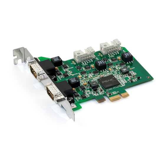
1 Introduction The plug-in card PCAN-PCI Express enables the connection of a PC with PCI Express slots to CAN networks. There is galvanic isolation of up to 500 V between the computer and CAN sides. The card is available as a single, double, or quad channel version. -
Page 5: Properties At A Glance
Power supply for external devices via CAN connection can be connected through a ■ solder jumper Extended operating temperature range from -40 to +85 °C (-40 to +185 °F) ■ 1 Introduction PCAN-PCI Express User Manual 4.0.0 © 2022 PEAK-System Technik GmbH... -
Page 6: System Requirements
PCI Express slot ■ a vacant slot for the slot bracket (only quad channel) ■ 1.3 Scope of Supply Plug-in card PCAN-PCI Express ■ Slot bracket with D-Sub connectors for the CAN bus (only quad channel) ■ Downloads Device drivers for Windows 11, 10 (32/64-bit) and Linux (32/64-bit) ■... -
Page 7: Setting
Set the solder bridge(s) corresponding to the desired settings. The following figure shows the solder field positions on the quad channel card. The table below contains the possible settings. 2 Setting PCAN-PCI Express User Manual 4.0.0 © 2022 PEAK-System Technik GmbH... - Page 8 CAN 4 JP400 Attention! The voltage supply for external devices is not protected separately. Therefore, turn off the computer before you connect and disconnect CAN cables or peripheral systems. 2 Setting PCAN-PCI Express User Manual 4.0.0 © 2022 PEAK-System Technik GmbH...
-
Page 9: Installation
3 Installation This chapter covers the software setup for the PCAN-PCI Express card in Windows and the installation of the card in the computer. Note: For installation on Linux, see Appendix D Linux. Install the driver before you install the CAN interface. -
Page 10: Installing The Pcan-Pci Express Card
3.2 Installing the PCAN-PCI Express card Attention! Electrostatic discharge (ESD) can damage or destroy components on the card. Take precautions to avoid ESD. 1. Shut down the computer. 2. Disconnect the computer’s power supply. 3. Open the computer case. 4. Insert the plug-in card into an available PCI Express slot and attach it to the slot. -
Page 11: Check Operational Readiness
The connected CAN interface is displayed. 3.3.1 Plug-in card is not listed The PCAN-PCI Express card uses the PCIe standard 1.0. It may happen that the card is not detected by the system. This may occur, when the PCIe standard on your system is newer than "1.0"... -
Page 12: Connecting The Can Bus
D-Sub plug, plug-in card CAN 1 to 4 Assignment +5 V (optional) CAN_GND CAN_Low CAN_High CAN_GND 6, 7, 8, 9, 10 4, 5, 8, 9 None 4 Connecting the CAN Bus PCAN-PCI Express User Manual 4.0.0 © 2022 PEAK-System Technik GmbH... -
Page 13: Cabling
The termination prevents interfering signal reflections and ensures the proper operation of the transceivers of the connected CAN nodes (CAN interfaces, control devices). The CAN interface PCAN-PCI Express does not have an internal termination. Use the CAN interface on a terminated CAN bus. 4.2.2 Example of a Connection This example shows a connection between the PCAN Interface and a control unit (ECU). -
Page 14: Example Application Under Windows
4.3 Example Application under Windows As an example application for accessing the CAN interface, run the CAN monitor PCAN-View from the Windows Start menu. 4 Connecting the CAN Bus PCAN-PCI Express User Manual 4.0.0 © 2022 PEAK-System Technik GmbH... -
Page 15: Can Monitor Pcan-View
In the following the initialization of a CAN interface is described as an example. Detailed information about using PCAN-View can be found in the program window under the menu item Help. 5 CAN Monitor PCAN-View PCAN-PCI Express User Manual 4.0.0 © 2022 PEAK-System Technik GmbH... -
Page 16: Can-Interface Initialize
2. If there are several CAN-Interfaces, select the desired interface. For multiple channels, select the desired channel from the list. 3. Enter the bit rate(s) and other settings according to the connected CAN bus. 5 CAN Monitor PCAN-View PCAN-PCI Express User Manual 4.0.0 © 2022 PEAK-System Technik GmbH... - Page 17 4. Confirm the entries with OK. The main window appears and displays the Receive / Transmit tab. 5. For initializing another channel or CAN-Interface, open another instance of PCAN- View. 5 CAN Monitor PCAN-View PCAN-PCI Express User Manual 4.0.0 © 2022 PEAK-System Technik GmbH...
-
Page 18: Transmit Can Message
4. To send the message manually, select the menu command Transmit > Send or press the |space| bar. The manual transmission process is performed additionally for periodically transmitted CAN messages. 5 CAN Monitor PCAN-View PCAN-PCI Express User Manual 4.0.0 © 2022 PEAK-System Technik GmbH... -
Page 19: Additional Tabs
5.3.1 Trace Tab The tracer (data logger) records the communication of the CAN bus in linear or ring buffer mode. The trace data can be saved to a file. 5 CAN Monitor PCAN-View PCAN-PCI Express User Manual 4.0.0 © 2022 PEAK-System Technik GmbH... - Page 20 CAN interface, a hardware ID can be determined to distinguish several interfaces of the same type. For interfaces with CAN FD a transmission according to "ISO" or "Non-ISO" can be set as default of the hardware. 5 CAN Monitor PCAN-View PCAN-PCI Express User Manual 4.0.0 © 2022 PEAK-System Technik GmbH...
- Page 21 5.3.3 Bus Load Tab The Bus Load tab displays the current bus load, its time history and statistical information of the connected CAN channel. 5.3.4 Error Generator Tab 5 CAN Monitor PCAN-View PCAN-PCI Express User Manual 4.0.0 © 2022 PEAK-System Technik GmbH...
- Page 22 You can destroy CAN frames with the error generator by one of two methods: once after activation ■ repeatedly at specific intervals related to a CAN ID ■ 5 CAN Monitor PCAN-View PCAN-PCI Express User Manual 4.0.0 © 2022 PEAK-System Technik GmbH...
- Page 23 4. Determine the Number of Frames to destroy. 5. Confirm the entries with Apply to activate the error generator. 6. Stop destroying further CAN frames with Disable. 5 CAN Monitor PCAN-View PCAN-PCI Express User Manual 4.0.0 © 2022 PEAK-System Technik GmbH...
-
Page 24: Api Pcan-Basic
The programming interface (API) PCAN-Basic provides basic functions for the connection of own programs to the CAN interface of PEAK-System. PCAN-Basic is the interface between the program and the device driver. In Windows operating systems this is a DLL (Dynamic Link Library) and in Linux operating systems an SO (Dynamic Shared Object). -
Page 25: Features Of Pcan-Basic
■ Windows 11, 10 (32/64-bit) ■ Linux (32/64-bit) ■ Multiple PEAK-System applications and your own can be operated on a physical ■ channel at the same time Single DLL (Win) / SO (Linux) for all supported hardware types ■ Use of up to 16 channels for each hardware type ■... -
Page 26: Principle Description Of The Api
To end the communication the function CAN_Uninitialize is called in order to release the reserved resources for the CAN channel, among others. In addition the CAN channel is marked as "Free" and is available to other applications. 6 API PCAN-Basic PCAN-PCI Express User Manual 4.0.0 © 2022 PEAK-System Technik GmbH... -
Page 27: Technical Specifications
-40 to +85 °C / -40 to +185 °F Temperature for storage and transport -40 to +125 °C / -40 to +257 °F Relative humidity 15 to 90 %, not condensing 7 Technical Specifications PCAN-PCI Express User Manual 4.0.0 © 2022 PEAK-System Technik GmbH... - Page 28 Conformity EU Directive 2011/65/EU (RoHS 2) + 2015/863/EU RoHS DIN EN IEC 63000:2019-05; VDE 0042-12:2019-05 EU Directive 2014/30/EU DIN EN 55024:2016-05; VDE 0878-24:2016-05 DIN EN 55032:2016-02; VDE 0878-32:2016-02 7 Technical Specifications PCAN-PCI Express User Manual 4.0.0 © 2022 PEAK-System Technik GmbH...
-
Page 29: Appendix A Ce Certificate
Appendix A CE Certificate Appendix A CE Certificate PCAN-PCI Express User Manual 4.0.0 © 2022 PEAK-System Technik GmbH... -
Page 30: Appendix B Dimension Drawing
Appendix B Dimension Drawing PCAN-PCI Express Quad Channel Appendix B Dimension Drawing PCAN-PCI Express User Manual 4.0.0 © 2022 PEAK-System Technik GmbH... -
Page 31: Appendix C Quick Reference
Turn off the computer and insert the card into an available PCI Express slot. The new hardware is detected at the next Windows start and the driver is initialized. Check the operational readiness. Open the Windows Start menu. Type Peak Settings and press |Enter|. The window PEAK settings appears. The connected CAN interface is displayed under CAN Hardware. -
Page 32: Appendix D Linux
Appendix D Linux Depending on the Kernel version, device drivers for the CAN interfaces from PEAK- System are already included in the operating system. The CAN interfaces are treated as network devices (SocketCAN, netdev). You can find the documentation for SocketCAN under: https://www.kernel.org/doc/Documentation/networking/can.txt...
Need help?
Do you have a question about the PCAN-PCI Express and is the answer not in the manual?
Questions and answers