Table of Contents
Advertisement
Quick Links
Advertisement
Table of Contents

Related Manuals for Peak PCAN-miniPCIe


Summary of Contents for Peak PCAN-miniPCIe
- Page 1 PCAN-miniPCIe User Manual User Manual 2.1.0 © 2023 PEAK-System Technik GmbH...
-
Page 2: Imprint
Dual Channel model but varies in equipment. Imprint PCAN is a registered trademark of PEAK-System Technik GmbH. CiA® is a registered community trade mark of CAN in Automation e.V. All other product names in this document may be the trademarks or registered trademarks of their respective companies. -
Page 3: Table Of Contents
5.2 Principle Description of the API 6 Technical Data Appendix A CE Certificate Appendix B UKCA Certificate Appendix C Dimension Drawings Appendix D Quick Reference Appendix E Linux Appendix F Disposal Contents PCAN-miniPCIe User Manual 2.1.0 © 2023 PEAK-System Technik GmbH... -
Page 4: Introduction
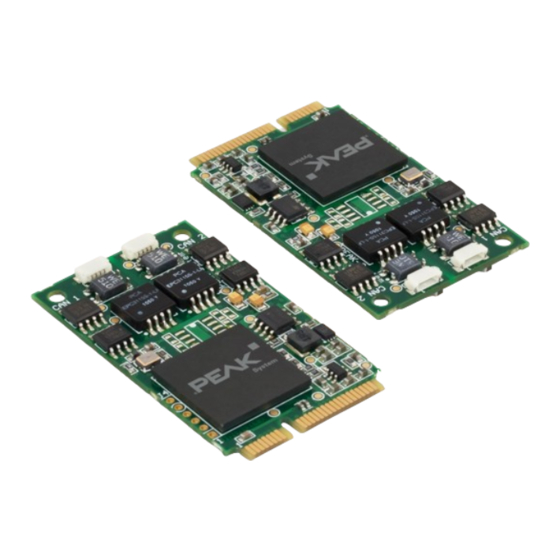
Introduction The PCAN-miniPCIe card enables the connection of embedded PCs and laptops with PCI Express Mini slots to CAN networks. There is galvanic isolation of up to 300 Volts between the computer and CAN sides. The card is available as a single or dual-channel version. -
Page 5: Scope Of Supply
CAN monitor PCAN-View for Windows ■ Programming interface PCAN-Basic for developing applications with CAN ■ connection Programming interfaces for standardized protocols from the automotive sector ■ Manual in PDF format ■ 1 Introduction PCAN-miniPCIe User Manual 2.1.0 © 2023 PEAK-System Technik GmbH... -
Page 6: Installation
Installation This chapter covers the software setup for the CAN interface PCAN-miniPCIe in Windows and the installation of the CAN interface in the computer. Note: For installation on Linux, see Appendix E Linux. Install the driver before you install the CAN interface. -
Page 7: Connect The Can Interface
7. Close the computer case. 8. Reconnect the computer power supply. 9. Turn on the computer and start Windows. Windows detects the new hardware and completes the driver installation. 2 Installation PCAN-miniPCIe User Manual 2.1.0 © 2023 PEAK-System Technik GmbH... -
Page 8: Check Operational Readiness
2.3 Check Operational Readiness 1. Open the Windows Start menu. 2. Type Peak Settings and press |Enter|. The window PEAK Settings appears. 3. Select CAN Hardware. The connected CAN interface is displayed. 2 Installation PCAN-miniPCIe User Manual 2.1.0 © 2023 PEAK-System Technik GmbH... -
Page 9: Connecting The Can Bus
The termination prevents interfering signal reflections and ensures the proper operation of the transceivers of the connected CAN nodes (CAN interfaces, control devices). The CAN interface PCAN-miniPCIe does not have an internal termination. Use the CAN interface on a terminated CAN bus. 3 Connecting the CAN Bus PCAN-miniPCIe User Manual 2.1.0... -
Page 10: Example Application Under Windows 10
3.3 Example Application under Windows As an example application for accessing the CAN interface, run the CAN monitor PCAN-View from the Windows Start menu. 3 Connecting the CAN Bus PCAN-miniPCIe User Manual 2.1.0 © 2023 PEAK-System Technik GmbH... -
Page 11: Can Monitor Pcan-View
In the following the initialization of a CAN interface is described as an example. Detailed information about using PCAN-View can be found in the program window under the menu item Help. 4 CAN Monitor PCAN-View PCAN-miniPCIe User Manual 2.1.0 © 2023 PEAK-System Technik GmbH... -
Page 12: Initialize Can Interface
Depending on the CAN interface the Connect dialog is displayed with or without settings for CAN FD. CAN FD CAN interface List entry in Available Hardware USB Interface, 1-channel see example above USB Interface, 2-channel PCIe Interface, 2-channel 4 CAN Monitor PCAN-View PCAN-miniPCIe User Manual 2.1.0 © 2023 PEAK-System Technik GmbH... - Page 13 4. Confirm the entries with OK. The main window appears and displays the Receive / Transmit tab. 5. For initializing another channel or CAN interface, open another instance of PCAN-View. 4 CAN Monitor PCAN-View PCAN-miniPCIe User Manual 2.1.0 © 2023 PEAK-System Technik GmbH...
-
Page 14: Transmit Can Message
4. To send the message manually, select the menu command Transmit > Send or press the |space| bar. The manual transmission process is performed additionally for periodically transmitted CAN messages. 4 CAN Monitor PCAN-View PCAN-miniPCIe User Manual 2.1.0 © 2023 PEAK-System Technik GmbH... -
Page 15: Additional Tabs
4.3.1 Trace Tab The tracer (data logger) records the communication of the CAN bus in linear or ring buffer mode. The trace data can be saved to a file. 4 CAN Monitor PCAN-View PCAN-miniPCIe User Manual 2.1.0 © 2023 PEAK-System Technik GmbH... - Page 16 4.3.2 CAN Interface Tab The CAN interface tab shows information about the hardware and the used Windows device driver. In this case exemplary for the PCAN-miniPCIe FD. Depending on the CAN interface, a hardware ID can be determined to distinguish several interfaces of the same type.
- Page 17 4.3.3 Bus Load Tab The Bus Load tab displays the current bus load, its time history and statistical information of the connected CAN channel. 4 CAN Monitor PCAN-View PCAN-miniPCIe User Manual 2.1.0 © 2023 PEAK-System Technik GmbH...
- Page 18 You can destroy CAN frames with the error generator by one of two methods: once after activation ■ repeatedly at specific intervals related to a CAN ID ■ 4 CAN Monitor PCAN-View PCAN-miniPCIe User Manual 2.1.0 © 2023 PEAK-System Technik GmbH...
- Page 19 4. Determine the Number of Frames to destroy. 5. Confirm the entries with Apply to activate the error generator. 6. Stop destroying further CAN frames with Disable. 4 CAN Monitor PCAN-View PCAN-miniPCIe User Manual 2.1.0 © 2023 PEAK-System Technik GmbH...
-
Page 20: Api Pcan-Basic
The programming interface (API) PCAN-Basic provides basic functions for the connection of own programs to the CAN and CAN FD Interfaces of PEAK-System. PCAN-Basic is the interface between the program and the device driver. In Windows operating systems this is a DLL (Dynamic Link Library) and in Linux operating systems an SO (Dynamic Shared Object). -
Page 21: Features Of Pcan-Basic
Use of a single DLL for all supported hardware types ■ Use of up to 16 channels for each hardware type (depending on the PEAK CAN ■ interface used) Simple switching between channels of a PEAK CAN interface ■... -
Page 22: Principle Description Of The Api
To end the communication the function CAN_Uninitialize is called in order to release the reserved resources for the CAN channel, among others. In addition the CAN channel is marked as "Free" and is available to other applications. 5 API PCAN-Basic PCAN-miniPCIe User Manual 2.1.0 © 2023 PEAK-System Technik GmbH... -
Page 23: Technical Data
30 x 51 x 4 mm Dual Channel 30 x 51 x 4 mm 20 cm Length connection cable Weight Single Channel Dual Channel Connection cable 7 g (each) Screw for D-Sub 1 (each) connector 6 Technical Data PCAN-miniPCIe User Manual 2.1.0 © 2023 PEAK-System Technik GmbH... - Page 24 15 to 90 %, not condensing Conformity RoHS EU Directive 2011/65/EU (RoHS 2) + 2015/863/EU DIN EN IEC 63000:2019-05 EU Directive 2014/30/EU DIN EN 55032:2022-08 DIN EN 55035:2018-04 6 Technical Data PCAN-miniPCIe User Manual 2.1.0 © 2023 PEAK-System Technik GmbH...
-
Page 25: Appendix Ace Certificate
German version of EN 55032:2015 + AC:2016 + A11:2020 + A1:2020 DIN EN 55035:2018-04 Electromagnetic compatibility of multimedia equipment - Immunity requirements (CISPR 35:2016, modified); German version of EN 55035:2017 Darmstadt, 29 August 2023 Uwe Wilhelm, Managing Director Appendix A CE Certificate PCAN-miniPCIe User Manual 2.1.0 © 2023 PEAK-System Technik GmbH... -
Page 26: Appendix B Ukca Certificate
German version of EN 55032:2015 + AC:2016 + A11:2020 + A1:2020 DIN EN 55035:2018-04 Electromagnetic compatibility of multimedia equipment - Immunity requirements (CISPR 35:2016, modified); German version of EN 55035:2017 Darmstadt, 29 August 2023 Uwe Wilhelm, Managing Director Appendix B UKCA Certificate PCAN-miniPCIe User Manual 2.1.0 © 2023 PEAK-System Technik GmbH... -
Page 27: Appendix C Dimension Drawings
Appendix C Dimension Drawings Dimensions in mm of PCAN-miniPCIe Single Channel and Dual Channel. Appendix C Dimension Drawings PCAN-miniPCIe User Manual 2.1.0 © 2023 PEAK-System Technik GmbH... -
Page 28: Appendix D Quick Reference
Install the driver before you install the CAN interface. Turn off the computer and insert the PCAN-miniPCIe into an available PCI Express Mini slot (using PCIe lane). The new hardware is detected at the next Windows start and the driver is initialized. -
Page 29: Appendix E Linux
Appendix E Linux Depending on the Kernel version, device drivers for the CAN interfaces from PEAK- System are already included in the operating system. The PCAN interfaces are handled as network devices (SocketCAN, netdev). You can find the documentation for SocketCAN under: https://www.kernel.org/doc/Documentation/networking/can.txt... -
Page 30: Appendix F Disposal
Appendix F Disposal The product must not be disposed of in household waste. Dispose of the product properly in accordance with local regulations. Appendix F Disposal PCAN-miniPCIe User Manual 2.1.0 © 2023 PEAK-System Technik GmbH...
Need help?
Do you have a question about the PCAN-miniPCIe and is the answer not in the manual?
Questions and answers