Table of Contents
Advertisement
Quick Links
User's Guide
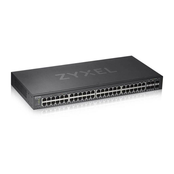
GS1920v2 Series
8/24/48-port GbE Smart Managed Switch
Default Login Details
Management IP
Address
User Name
Password
Copyright © 2023 Zyxel and/or its affiliates. All Rights Reserved.
http://setup.zyxel
or
http://DHCP-assigned IP
or
192.168.1.1
admin
1234
Version 4.80 Edition 1, 03/2023
Advertisement
Table of Contents
Troubleshooting

Related Manuals for ZyXEL Communications GS1920v2 Series


Summary of Contents for ZyXEL Communications GS1920v2 Series
- Page 1 User’s Guide GS1920v2 Series 8/24/48-port GbE Smart Managed Switch Default Login Details Version 4.80 Edition 1, 03/2023 Management IP http://setup.zyxel Address http://DHCP-assigned IP 192.168.1.1 User Name admin Password 1234 Copyright © 2023 Zyxel and/or its affiliates. All Rights Reserved.
- Page 2 Go to nebula.zyxel.com support.zyxel.com to get this User’s Guide on how to configure the Switch using Nebula. • More Information Go to https://community.zyxel.com/en for product discussions. Go to support.zyxel.com to find other information on the Switch. GS1920v2 Series User’s Guide...
-
Page 3: Document Conventions
Figures in this user guide may use the following generic icons. The Switch icon is not an exact representation of your device. Switch Generic Router Wireless Router / Access Point Generic Switch Smart TV Desktop Laptop IP Camera Printer Server GS1920v2 Series User’s Guide... -
Page 4: Table Of Contents
Time Range ............................155 PORT ..............................158 Green Ethernet ........................... 159 Link Aggregation ..........................161 Link Layer Discovery Protocol (LLDP) ....................169 OAM ..............................192 PoE Setup ............................. 200 Port Setup ............................207 SWITCHING ............................209 GS1920v2 Series User’s Guide... - Page 5 Storm Control ............................378 Error-Disable ............................380 IP Source Guard ..........................386 DHCP Snooping ..........................391 ARP Inspection ............................ 403 Port Authentication ..........................411 Port Security ............................421 MAINTENANCE ............................ 424 Troubleshooting and Appendices ....................445 Troubleshooting ..........................446 GS1920v2 Series User’s Guide...
-
Page 6: Table Of Contents
2.4.3 Attaching the Mounting Brackets to the Switch ............... 35 2.4.4 Mounting the Switch under a Table ................... 35 2.5 Wall Mounting (GS1920-8HPv2 Only) .................... 36 2.5.1 Installation Requirements ..................... 36 2.6 Mounting the Switch on a Rack ....................38 2.6.1 Installation Requirements ..................... 38 GS1920v2 Series User’s Guide... - Page 7 4.7.2 Restore Custom Default ....................... 67 4.7.3 Reboot the Switch ........................ 67 4.8 Log Out of the Web Configurator ....................67 4.9 Help ..............................67 Chapter 5 Initial Setup Example .........................69 5.1 Overview ............................69 5.1.1 Create a VLAN ........................69 GS1920v2 Series User’s Guide...
- Page 8 Chapter 11 MAC Table ............................91 11.1 MAC Table Overview ........................91 11.1.1 What You Can Do ....................... 91 11.1.2 What You Need to Know ....................91 11.2 Viewing the MAC Table ....................... 92 Chapter 12 Neighbor ............................94 GS1920v2 Series User’s Guide...
- Page 9 Cloud Management ........................111 18.1 Cloud Management Overview ....................111 18.2 Nebula Center Control Discovery .................... 111 Chapter 19 General Setup ..........................114 19.1 General Setup ..........................114 Chapter 20 Interface Setup..........................117 20.1 Interface Setup Overview ......................117 GS1920v2 Series User’s Guide...
- Page 10 22.9.1 Edit DHCPv6 Client ......................137 Chapter 23 Logins ..............................139 23.1 Set Up Login Accounts ....................... 139 Chapter 24 SNMP ..............................141 24.1 SNMP Overview .......................... 141 24.1.1 What You Can Do ......................141 24.2 Configure SNMP .......................... 141 GS1920v2 Series User’s Guide...
- Page 11 30.1.1 What You Can Do ......................161 30.1.2 What You Need to Know ....................161 30.2 Link Aggregation Status ......................162 30.3 Link Aggregation Setting ......................164 30.4 Link Aggregation Control Protocol ................... 165 30.5 Technical Reference ........................167 GS1920v2 Series User’s Guide...
- Page 12 33.1 PoE Status (for PoE models only) ....................200 33.2 PoE Setup ............................. 202 33.3 PoE Time Range Setup ....................... 205 33.3.1 Add/Edit PoE Time Range ....................206 Chapter 34 Port Setup............................207 34.1 Port Setup ............................ 207 Chapter 35 SWITCHING............................209 GS1920v2 Series User’s Guide...
- Page 13 39.9 MLD Snooping-proxy Port Role Setting ..................234 39.10 MLD Snooping-proxy Filtering ....................236 39.11 MLD Snooping-proxy Filtering Profile ..................237 39.11.1 Add MLD Snooping-proxy Filtering Profile ..............238 39.11.2 Add MLD Snooping-proxy Filtering Rule ............... 239 39.12 MVR Configuration ........................239 GS1920v2 Series User’s Guide...
- Page 14 43.1.1 What You Can Do ......................261 43.1.2 What You Need to Know ....................261 43.2 Configuring Queuing ......................... 262 Chapter 44 Priority Queue...........................264 44.1 Priority Queue Overview ......................264 44.1.1 What You Can Do ......................264 GS1920v2 Series User’s Guide...
- Page 15 47.2.1 Add/Edit a Static MAC Filtering Rule ................291 Chapter 48 Static MAC Forwarding........................292 48.1 Static MAC Forwarding Overview .................... 292 48.1.1 What You Can Do ......................292 48.2 Configure Static MAC Forwarding ................... 292 48.2.1 Add/Edit Static MAC Forwarding Rules ................293 GS1920v2 Series User’s Guide...
- Page 16 50.2 Configuring VLAN Isolation ......................319 50.2.1 Add/Edit a VLAN Isolation Rule ..................320 Chapter 51 NETWORKING............................322 Chapter 52 ARP Setup............................323 52.1 ARP Overview ..........................323 52.1.1 What You Can Do ......................323 52.1.2 What You Need to Know ....................323 GS1920v2 Series User’s Guide...
- Page 17 56.2 RADIUS Server Setup ........................345 56.3 TACACS+ Server Setup ....................... 347 56.4 AAA Setup ........................... 349 56.5 Technical Reference ........................352 56.5.1 Vendor Specific Attribute ....................352 56.5.2 Supported RADIUS Attributes ................... 353 56.5.3 Attributes Used for Authentication .................. 354 GS1920v2 Series User’s Guide...
- Page 18 60.1 Storm Control Overview ......................378 60.1.1 What You Can Do ......................378 60.2 Storm Control Setup ........................378 Chapter 61 Error-Disable .............................380 61.1 Error-Disable Overview ....................... 380 61.1.1 CPU Protection Overview ....................380 61.1.2 Error-Disable Recovery Overview ..................380 GS1920v2 Series User’s Guide...
- Page 19 64.7 Technical Reference ........................409 64.7.1 ARP Inspection Overview ....................409 Chapter 65 Port Authentication ..........................411 65.1 Port Authentication Overview ....................411 65.1.1 What You Can Do ......................411 65.1.2 What You Need to Know ....................412 GS1920v2 Series User’s Guide...
- Page 20 67.10 Erase Running-Configuration ....................435 67.11 Save Configuration ........................436 67.12 Configure Clone ........................436 67.13 Diagnostic ..........................438 67.14 Firmware Upgrade ........................440 67.15 Reboot System .......................... 442 67.16 Tech-Support ..........................443 67.16.1 Tech-Support Download ....................444 GS1920v2 Series User’s Guide...
- Page 21 68.3 Switch Configuration ........................449 68.4 PoE Supply ........................... 449 68.5 Nebula Registration ........................450 Appendix A Customer Support ..................... 451 Appendix B Common Services ...................... 456 Appendix C IPv6..........................459 Appendix D Legal Information ...................... 467 Index ..............................472 GS1920v2 Series User’s Guide...
-
Page 22: User's Guide
User’s Guide... -
Page 23: Getting To Know Your Switch
H A P T E R Getting to Know Your Switch 1.1 Introduction This chapter introduces the main features and applications of the Switch. The GS1920v2 Series consists of the following models: • GS1920-8HPv2 • GS1920-24v2 • GS1920-24HPv2 • GS1920-48v2 •... -
Page 24: Management Modes
See the NCC (Nebula Control Center) User’s Guide for how to configure the Switch using Nebula. Figure 1 NCC Example Network Topology 1.1.2 Mode Changing This section describes how to change the Switch’s management mode. Refer to the Switch’s standalone mode User’s Guide for LED descriptions, including CLOUD LED behavior. GS1920v2 Series User’s Guide... - Page 25 Nebula web portal. To access the Web Configurator when the Switch is in Cloud mode, use the Local credentials password to login. GS1920v2 Series User’s Guide...
-
Page 26: Zon Utility
You can download the ZON Utility at www.zyxel.com and install it on a PC (Windows operation system). For more information on ZON Utility see Section 4.3 on page GS1920v2 Series User’s Guide... -
Page 27: Poe
The GS1920-8HPv2, GS1920-24HPv2, and GS1920-48HPv2 support the IEEE 802.3at High Power over Ethernet (PoE) standard and IEEE 802.3af PoE standard. Key feature differences between Switch models are as follows. Other features are common to all models. GS1920v2 Series User’s Guide... -
Page 28: Example Applications
The Switch is an ideal solution for small networks where rapid growth can be expected in the near future. The Switch can be used standalone for a group of heavy traffic users. You can connect computers and servers directly to the Switch’s port or connect other switches to the Switch. GS1920v2 Series User’s Guide... -
Page 29: Bridging Or Fiber Optic Uplink Example Application
You can provide a super-fast uplink connection by using a Gigabit Ethernet or SFP port on the Switch. Moreover, the Switch eases supervision and maintenance by allowing network managers to centralize multiple servers at a single location. GS1920v2 Series User’s Guide... -
Page 30: High Performance Switching Example
Stations on a logical network belong to one or more groups. With VLAN, a station cannot directly talk to or hear from stations that are not in the same groups unless such traffic first goes through a router. GS1920v2 Series User’s Guide... -
Page 31: Ways To Manage The Switch
• ZON Utility. ZON Utility is a program designed to help you deploy and perform initial setup on a network more efficiently. See Section 4.3 on page 1.4 Good Habits for Managing the Switch Do the following regularly to make the Switch more secure and to manage the Switch more effectively. GS1920v2 Series User’s Guide... - Page 32 Switch to its factory default settings. If you backed up an earlier configuration file, you would not have to totally re-configure the Switch. You could simply restore your last configuration. GS1920v2 Series User’s Guide...
-
Page 33: Hardware Installation And Connection
• The Switches with fans are not suitable for use in locations where children are likely to be present. To start using the Switch, simply connect the power cables to turn it on. 2.3 Freestanding Installation Procedure Make sure the Switch is clean and dry. GS1920v2 Series User’s Guide... -
Page 34: Desk Mounting (Gs1920-8Hpv2 Only)
• Make sure to place the Switch horizontally under a smooth level surface. • Make sure the table is sturdy enough for desk mounting. • Make sure there is enough table thickness to drill screws. • Make sure there is sufficient space for port connections. GS1920v2 Series User’s Guide... -
Page 35: Attaching The Mounting Brackets To The Switch
Position the Switch in place and mark the places for drilling with the attached brackets. Drill holes at the marked places under the table. Line up the two screw holes on the bracket with the screw holes under the table. Figure 9 Mounting the Switch under a Table GS1920v2 Series User’s Guide... -
Page 36: Wall Mounting (Gs1920-8Hpv2 Only)
0.5 cm. If not using screw anchors, use a screwdriver to insert the screws into the wall. Do NOT insert the screws all the way in – leave a gap of about 0.5 cm. GS1920v2 Series User’s Guide... - Page 37 WARNING! The Switch should be wall-mounted horizontally, and make sure the front panel is facing down. The Switch's side panels with ventilation slots should not be facing up or down as this position is less safe. GS1920v2 Series User’s Guide...
-
Page 38: Mounting The Switch On A Rack
Position a mounting bracket (that is already attached to the Switch) on one side of the rack, lining up the two screw holes on the bracket with the screw holes on the side of the rack. GS1920v2 Series User’s Guide... - Page 39 Using a #2 Philips screwdriver, install the M5 flat head screws through the mounting bracket holes into the rack. Note: Make sure you tighten all the four screws to prevent the Switch from getting slanted. Repeat steps to attach the second mounting bracket on the other side of the rack. GS1920v2 Series User’s Guide...
-
Page 40: Hardware Panels
An auto-negotiating port can detect and adjust to the optimum Ethernet speed (10/100/1000 Mbps) and duplex mode (full duplex or half duplex) of the connected device. An auto-crossover (auto-MDI/MDI-X) port automatically works with a straight-through or crossover GS1920v2 Series User’s Guide... -
Page 41: Poe (Gs1920-8Hpv2, Gs1920-24Hpv2, And Gs1920-48Hpv2)
You can change transceivers while the Switch is operating. You can use different transceivers to connect to Ethernet switches with different types of fiber optic or even copper cable connectors. • Type: SFP connection interface • Connection speed: 100/1000 Mbps GS1920v2 Series User’s Guide... - Page 42 Remove the dust plugs from the transceiver and cables (dust plug styles vary). Identify the signal transmission direction of the fiber optic cables and the transceiver. Insert the fiber optic cable into the transceiver. Figure 17 Latch in the Lock Position Figure 18 Transceiver Installation Example GS1920v2 Series User’s Guide...
- Page 43 Switch and transceiver. Insert the dust plug into the ports on the transceiver and the cables. Figure 20 Removing the Fiber Optic Cables Figure 21 Opening the Transceiver’s Latch Example Figure 22 Transceiver Removal Example GS1920v2 Series User’s Guide...
-
Page 44: Rear Panel
Switch which may not be covered by its warranty. Note: The specification for surge or ESD protection assumes that the Switch is properly grounded. Remove the M4 ground screw from the Switch’s rear panel. GS1920v2 Series User’s Guide... - Page 45 Make sure the grounding terminal is connected to the buildings grounding electrode and has an earth resistance of less than 10 ohms, or according to your country’s electrical regulations. Figure 30 Connecting to the Building’s Main Grounding Electrode GS1920v2 Series User’s Guide...
-
Page 46: Ac Power Connection
Connect the other end of the cord to a power outlet. Disconnecting the Power The power input connectors can be disconnected from the power source individually. Disconnect the power cord from the power outlet. Disconnect the power cord from the AC power socket. GS1920v2 Series User’s Guide... -
Page 47: Leds
Blinking Shows the actual location of the Switch between several devices in a rack. The default timer is 30 minutes when you are configuring the Switch. The locator is not functioning or malfunctioning. GS1920v2 Series User’s Guide... - Page 48 1 – 8 Amber Power supplied to all PoE Ethernet ports meets the IEEE 802.3af (GS1920-8HPv2) standard. 1 – 24 There is no power supplied. (GS1920- 24HPv2) 1 – 48 (GS1920- 48HPv2) Dual Personality Interface GS1920v2 Series User’s Guide...
- Page 49 The Switch is transmitting or receiving data 1000 Mbps. Amber The uplink port is linking at 100 Mbps. Blinking The Switch is transmitting or receiving data 100 Mbps. There is no link or port, the uplink port is shut down. GS1920v2 Series User’s Guide...
-
Page 50: Technical Reference
Technical Reference... -
Page 51: Web Configurator
[ENTER]. Your computer must be in the same subnet in order to access this website address. Also, you can use the ZON Utility to check your Switch’s IP address. See Section 4.3 on page 54 for more information on the ZON utility. The Login screen appears. GS1920v2 Series User’s Guide... - Page 52 Switch to Nebula Cloud management. Figure 32 Visit Nebula Alternatively, click Login to log into the Web Configurator to manage the Switch directly. The default user name is admin and associated default password is 1234. GS1920v2 Series User’s Guide...
- Page 53 Enter the existing system password (1234 is the default password when shipped). New Password Enter your new system password. Up to 32 printable ASCII characters are allowed for the new password. Retype to confirm Re-enter your new system password for confirmation. GS1920v2 Series User’s Guide...
-
Page 54: Zyxel One Network (Zon) Utility
At the time of writing, the ZON Utility is compatible with: • Windows 7 (both 32-bit / 64-bit versions) • Windows 8 (both 32-bit / 64-bit versions) • Windows 8.1 (both 32-bit / 64-bit versions) • Windows 10 (both 32-bit / 64-bit versions) GS1920v2 Series User’s Guide... -
Page 55: Run The Zon Utility
ZON icon in the upper right of the screen. Then select the Supported model and firmware version link. If your device is not listed here, see the device release notes for ZON Utility support. The release notes are in the firmware zip file on the Zyxel web site. GS1920v2 Series User’s Guide... - Page 56 Select a network adapter to which your supported devices are connected. Figure 37 Network Adapter Click the Go button for the ZON Utility to discover all supported devices in your network. Figure 38 Discovery The ZON Utility screen shows the devices discovered. GS1920v2 Series User’s Guide...
- Page 57 Zyxel website to your computer and unzipped it in advance. 8 Change Password Use this icon to change the admin password of the selected device. You must know the current admin password before changing to a new one. GS1920v2 Series User’s Guide...
-
Page 58: Web Configurator Layout
The DASHBOARD screen is the first screen that displays when you access the Web Configurator. This guide uses the GS1920-8HP screens as examples. The screens may vary slightly for different models. The following figure shows the navigating components of a Web Configurator screen. GS1920v2 Series User’s Guide... - Page 59 SYSTEM > Cloud Management screen and check the diagnostic messages. See Section Table 27 on page 113 for more information. In the navigation panel, click a main link to reveal a list of sub-menu links. GS1920v2 Series User’s Guide...
- Page 60 IPv6 neighbor entries in the Switch’s IPv6 neighbor table. Neighbor Setup DHCPv6 This link takes you to a screen where you can configure the Switch’s DHCP settings when it is act- Client ing as a DHCPv6 client. Setup GS1920v2 Series User’s Guide...
- Page 61 By MAC PPPoE Interme- This link takes you to screens where you can enable PPPoE (Point-to-Point Protocol over Ethernet) diate Agent Intermediate Agent and configure per-port, per-port-per-VLAN settings. Click the link to unfold the following sub-link menu. GS1920v2 Series User’s Guide...
- Page 62 MAC address to create a MAC address filter and enter a weight to set the VLAN rule’s priority. VLAN Isolation This link takes you to a screen where you can block traffic between ports in a VLAN on the Switch. GS1920v2 Series User’s Guide...
- Page 63 This link takes you to screens where you can view ARP inspection status, and configure ARP Inspection inspection settings on ports or VLANs. You can use ARP inspection to filter unauthorized ARP pack- ets on the network. GS1920v2 Series User’s Guide...
-
Page 64: Tables And Lists
Tables have tool icons for working with table entries as shown next. You can select one or more entries, or select the check box in the heading row to select all entries. Use the tool icons to modify the selected entries. GS1920v2 Series User’s Guide... -
Page 65: Change Your Password
Figure 43 Working on a List 4.4.2 Change Your Password After you log in for the first time, it is recommended you change the default administrator password. Click SYSTEM > Logins to display the next screen. GS1920v2 Series User’s Guide... -
Page 66: Save Your Configuration
Delete all port-based VLANs with the CPU port as a member. The “CPU port” is the management port of the Switch. Filter all traffic to the CPU port. Disable all ports. Misconfigure the text configuration file. GS1920v2 Series User’s Guide... -
Page 67: Reset The Switch
Click Logout in a screen to exit the Web Configurator. You have to log in with your password again after you log out. This is recommended after you finish a management session for security reasons. Figure 45 Logout button 4.9 Help The Web Configurator’s online help has descriptions of individual screens and some supplementary information. GS1920v2 Series User’s Guide... - Page 68 Chapter 4 Web Configurator Click the Help icon on a Web Configurator screen to view an online help description (shown as below) of that screen. Figure 46 Online Web Help GS1920v2 Series User’s Guide...
-
Page 69: Initial Setup Example
In this example, you want to configure port 1 as a member of VLAN 2. Figure 47 Initial Setup Network Example: VLAN Go to the SWITCHING > VLAN > VLAN Setup > Static VLAN screen. Click Add/Edit. GS1920v2 Series User’s Guide... -
Page 70: Set Port Vid
In the example network, configure 2 as the port VID on port 1 so that any untagged frames received on that port get sent to VLAN 2. Figure 48 Initial Setup Network Example: Port VID Go to the SWITCHING > VLAN > VLAN Setup > VLAN Port Setup screen. GS1920v2 Series User’s Guide... -
Page 71: Configure Switch Management Ip Address
Connect your computer to any Ethernet port on the Switch. Make sure your computer is in the same subnet as the Switch. Open your web browser and enter “setup.zyxel” or “192.168.1.1” (the default IP address) in the address bar to access the Web Configurator. See Section 4.2 on page 51 for more information. GS1920v2 Series User’s Guide... - Page 72 In this example, enter VLAN ID 2. This is the same as the VLAN ID you configure in the Static VLAN screen. Click Apply to save your changes back to the run-time memory. Settings in the run-time memory are lost when the Switch’s power is turned off. GS1920v2 Series User’s Guide...
-
Page 73: Tutorials
Connect your computer to the out-of-band management port (So you can access the Switch without affected by any IP change caused by configurations). Access the Switch through http://192.168.0.1. Access the Switch through http://192.168.1.1 by default. Log into the Switch by entering the user name (default: admin) and password (default: 1234). GS1920v2 Series User’s Guide... - Page 74 Go to SWITCHING > VLAN > VLAN Setup > VLAN Port Setup, and set the PVID of the ports 4, 5 and 6 to 100. This tags untagged incoming frames on ports 4, 5 and 6 with the tag 100. Click Apply. GS1920v2 Series User’s Guide...
- Page 75 Go to SECURITY > IPv4 Source Guard > DHCP Snooping > DHCP Snp. Port Setup. Select Trusted in the Server Trusted state field for port 4 because the DHCP server is connected to port 4. Keep ports 5 and 6 Untrusted because they are connected to DHCP clients. Click Apply. GS1920v2 Series User’s Guide...
- Page 76 Click Save at the top right of the Web Configurator to save the configuration permanently. 10 To check if DHCP snooping works, go to SECURITY > IPv4 Source Guard > IP Source Guard, you should see an IP assignment with the type DHCP-Snooping as shown. GS1920v2 Series User’s Guide...
-
Page 77: How To Use Dhcpv4 Relay On The Switch
Follow the steps below to configure port 2 as a member of VLAN 102. Access the Web Configurator through the Switch’s management port. Go to SYSTEM > Switch Setup and set the VLAN Type to 802.1Q. Click Apply to save the settings to the run-time memory. GS1920v2 Series User’s Guide... - Page 78 Go to SWITCHING > VLAN > VLAN Setup > Static VLAN. Click Add/Edit. The following screen appears. Enable the switch button to set this VLAN to Active. Enter a descriptive name (VLAN 102 for example) in the Name field and enter “102” in the VLAN Group ID field. GS1920v2 Series User’s Guide...
- Page 79 Go to VLAN > VLAN Setup >VLAN Port Setup. Enter “102” in the PVID field for port 2 to add a tag to incoming untagged frames received on that port so that the frames are forwarded to the VLAN group that the tag defines. GS1920v2 Series User’s Guide...
-
Page 80: Configure Dhcpv4 Relay
You configured the correct VLAN ID, port number and system name for DHCP relay on both the DHCP server and the Switch. You clicked the Save link on the Switch to have your settings take effect. GS1920v2 Series User’s Guide... -
Page 81: Dashboard
This screen displays general device information, system status, system resource usage, and port status. This guide uses GS1920-8HP screens as an example. The screens may vary slightly for different models. Click DASHBOARD in the navigation panel to open the following screen. GS1920v2 Series User’s Guide... - Page 82 This field displays the serial number of this Switch. The serial number is used for device tracking Number and control. Hardware This field displays the hardware version of the Switch. Version System MAC This field displays the MAC address of the Switch. Address GS1920v2 Series User’s Guide...
- Page 83 Switch can provide to the connected PDs. It also shows the percentage of PoE power usage. When PoE usage reaches 100%, the Switch will shut down PDs one-by-one according to the PD priority which you configured in PORT > PoE Setup > PoE Setup. GS1920v2 Series User’s Guide...
-
Page 84: Port Status
The port details pane includes the Power Cycle button for PoE models (turn the power off and then back on again), displays information such as link speed, status, PoE draw (for PoE models), port utilization, up time and has an ON/OFF switch button. Click the switch button to enable/disable the port. GS1920v2 Series User’s Guide... -
Page 85: Quick Links To Use
The setup panel displays after you click the Edit button. Figure 56 Quick Link Selection (example PoE model) Select the quick links you want and click Apply. The selected quick links will be displayed in the Quick Link section on the DASHBOARD screen. GS1920v2 Series User’s Guide... -
Page 86: Monitor
The following chapters introduces the configurations of the links under the MONITOR navigation panel. Quick links to chapters: • ARP Table • IPv6 Neighbor Table • MAC Table • Neighbor • Path MTU Table • Port Status • System Information • System Log GS1920v2 Series User’s Guide... -
Page 87: Arp Table
MAC address that replied. 9.2 Viewing the ARP Table Use the ARP table to view IP-to-MAC address mappings and remove specific dynamic ARP entries. Click MONITOR > ARP Table in the navigation panel to open the following screen. GS1920v2 Series User’s Guide... - Page 88 This shows 0 for a static entry. Type This shows whether the IP address is dynamic (learned by the Switch) or static (manually configured in SYSTEM > IP Setup > IP Setup or NETWORKING > ARP Setup > Static ARP). GS1920v2 Series User’s Guide...
-
Page 89: Ipv6 Neighbor Table
10.2 Viewing the IPv6 Neighbor Table Use this screen to view IPv6 neighbor information on the Switch. Click MONITOR > IPv6 Neighbor Table in the navigation panel to display the screen as shown. Figure 58 MONITOR > IPv6 Neighbor Table GS1920v2 Series User’s Guide... - Page 90 Click this button to display and arrange the data according to IPv6 address. Click this button to display and arrange the data according to MAC address. Interface Click this button to display and arrange the data according to IPv6 interface. GS1920v2 Series User’s Guide...
-
Page 91: Mac Table
MAC address. The Switch then learns the port that replies with the MAC address. • If the Switch has already learned the port for this MAC address, but the destination port is the same as the port it came in on, then it filters the frame. GS1920v2 Series User’s Guide... -
Page 92: Viewing The Mac Table
MAC forwarding table or MAC filtering table from the MAC table using this screen. Click MONITOR > MAC Table in the navigation panel to display the following screen. Figure 60 MONITOR > MAC Table GS1920v2 Series User’s Guide... - Page 93 This is the port where the above MAC address is forwarded. Type This shows whether the MAC address is Dynamic (learned by the Switch) or Static (manually entered in the SWITCHING > Static MAC Forwarding screen). GS1920v2 Series User’s Guide...
-
Page 94: Neighbor
(Section 12.2.1 on page 95) to view more detailed information on the Switch’s neighbor devices. 12.2 Neighbor Click MONITOR > Neighbor to see the following screen. Figure 61 MONITOR > Neighbor > Neighbor (example PoE model) GS1920v2 Series User’s Guide... -
Page 95: Neighbor Details
When the maximum number of neighboring device records per Ethernet port is reached, new device records automatically overwrite existing offline device records, starting with the oldest existing offline device record first. Click MONITOR > Neighbor > Neighbor Details to see the following screen. GS1920v2 Series User’s Guide... - Page 96 ZON utility. This shows the MAC address of the neighbor device. Firmware This shows the firmware version of the neighbor device. This field will show “–” for devices that do not support the ZON utility. GS1920v2 Series User’s Guide...
- Page 97 You can only reset Zyxel powered devices that support the ZON utility. Flush Click the Flush button on the port tab to remove information about neighbors learned on a specific ports. Flush All Click the Flush All button to remove information about neighbors learned on all ports. GS1920v2 Series User’s Guide...
-
Page 98: Path Mtu Table
This field displays the maximum transmission unit of the links in the path. Expire This field displays how long (in minutes) an entry can still remain in the Path MTU table before it ages out and needs to be relearned. GS1920v2 Series User’s Guide... -
Page 99: Port Status
MONITOR > Port Status to display the Port Status screen as shown next. You can also click the Port Status link in the Quick Link section of the DASHBOARD screen to see the following screen. Figure 64 MONITOR > Port Status > Port Status GS1920v2 Series User’s Guide... -
Page 100: Port Details
Click an index in the Port column in the MONITOR > Port Status > Port Status screen to display individual port statistics. Use this screen to check status and detailed performance data about an individual port on the Switch. GS1920v2 Series User’s Guide... - Page 101 This field shows the number of received frames on this port. Errors This field shows the number of received errors on this port. Tx kB/s This field shows the number of kilobytes per second transmitted on this port. GS1920v2 Series User’s Guide...
- Page 102 This field shows the number of packets (including bad packets) received that were between 128 and 255 octets in length. 256 to 511 This field shows the number of packets (including bad packets) received that were between 256 and 511 octets in length. GS1920v2 Series User’s Guide...
-
Page 103: Ddmi
14.2.1 DDMI Details Use this screen to view the real-time SFP (Small Form Factor Pluggable) transceiver information and operating parameters on the SFP port. The parameters include, for example, transmitting and receiving power, and module temperature. GS1920v2 Series User’s Guide... - Page 104 Switch if the monitored DDMI parameter reaches this value. High Warn This displays the high value warning threshold for each monitored DDMI parameter. A warning Threshold signal is reported to the Switch if the monitored DDMI parameter reaches this value. GS1920v2 Series User’s Guide...
-
Page 105: Port Utilization
This field shows the transmission speed of data received on this port in kilobytes per second. Rx Utilization% This field shows the percentage of actual received frames on this port as a percentage of the Link speed. GS1920v2 Series User’s Guide... -
Page 106: System Information
Switch. 15.1 System Information In the navigation panel, click MONITOR > System Information to display the screen as shown. Use this screen to view general system information. Figure 69 MONITOR > System Information GS1920v2 Series User’s Guide... - Page 107 The power supply for each voltage has a sensor that is capable of detecting and reporting if the voltage falls out of the tolerance range. Status Normal indicates that the voltage is within an acceptable operating range at this point; otherwise Error is displayed. GS1920v2 Series User’s Guide...
- Page 108 This field displays the maximum voltage measured at this point. This field displays the minimum voltage measured at this point. Threshold This field displays the percentage tolerance of the voltage with which the Switch still works. GS1920v2 Series User’s Guide...
-
Page 109: System Log
The summary table shows the time the log message was recorded and the reason the log message was generated. Click Refresh to update this screen. Click Clear to clear the whole log, regardless of what is currently displayed on the screen. Click Download to save the log to your computer. GS1920v2 Series User’s Guide... -
Page 110: System
The following chapters introduces the configurations of the links under the SYSTEM navigation panel. Quick links to chapters: • Cloud Management • General Setup • Interface Setup • IP Setup • IPv6 • Logins • SNMP • Switch Setup • Syslog Setup • Time Range GS1920v2 Series User’s Guide... -
Page 111: Cloud Management
• It is connected to the Internet. • The Nebula Control Center (NCC) Discovery feature is enabled. • It has been registered in the NCC. 18.2 Nebula Center Control Discovery Click SYSTEM > Cloud Management to display this screen. GS1920v2 Series User’s Guide... - Page 112 Chapter 18 Cloud Management Figure 71 SYSTEM > Cloud Management GS1920v2 Series User’s Guide...
- Page 113 Follow the wizard in the Nebula Mobile app to scan the QR code to register the Switch on NCC and add the Switch into a site. If Nebula Control Center (NCC) Discovery is disabled, the Switch will NOT discover the NCC and remain in Standalone mode. GS1920v2 Series User’s Guide...
-
Page 114: General Setup
Enter the geographic location of your Switch. You can use up to 128 printable ASCII characters; spaces are allowed. Contact Person's Enter the name of the person in charge of this Switch. You can use up to 32 printable ASCII Name characters; spaces are allowed. GS1920v2 Series User’s Guide... - Page 115 UTC). So in the European Union you would select Last, Sunday, October and the last field depends on your time zone. In Germany for instance, you would select 2:00 because Germany's time zone is one hour ahead of GMT or UTC (GMT+1). GS1920v2 Series User’s Guide...
- Page 116 Save link on the top navigation panel to save your changes to the non-volatile memory when you are done configuring. Cancel Click Cancel to begin configuring this screen afresh. GS1920v2 Series User’s Guide...
-
Page 117: Interface Setup
Select an entry’s check box to select a specific entry. Otherwise, select the check box in the table heading row to select all entries. Add/Edit Click Add/Edit to add a new interface or edit a selected one. Delete Click Delete to remove the selected interfaces. GS1920v2 Series User’s Guide... -
Page 118: Add/Edit Interfaces
Clear Click Clear to clear the fields to the factory defaults. Cancel Click Cancel to not save the configuration you make and return to the last screen. GS1920v2 Series User’s Guide... -
Page 119: Ip Setup
VLANs. Note: You must configure a VLAN first. Each VLAN can only have one management IP address. 21.2 IP Status Click SYSTEM > IP Setup > IP Status to display the screen as shown. GS1920v2 Series User’s Guide... -
Page 120: Ip Status Details
21.2.1 IP Status Details Use this screen to view IP status details. Click a number in the Index column in the SYSTEM > IP Setup > IP Status screen to display the screen as shown next. GS1920v2 Series User’s Guide... - Page 121 This is the IP subnet mask of your Switch in dotted decimal notation for example 255.255.255.0. Lease Time This displays the length of time in seconds that this interface can use the current dynamic IP address from the DHCP server. GS1920v2 Series User’s Guide...
-
Page 122: Ip Setup
Note: The Switch allows you to set a static IP interface in the same subnet that already has a DHCP-assigned IP interface on the Switch. The Switch will use the static IP you set and the DHCP-assigned IP will be set to 0.0.0.0. Figure 78 SYSTEM > IP Setup > IP Setup GS1920v2 Series User’s Guide... -
Page 123: Add/Edit Ip Interfaces
21.3.1 Add/Edit IP Interfaces Use this screen to add or edit IP interfaces. Click Add/Edit, or select an entry and click Add/Edit in the SYSTEM > IP Setup > IP Setup screen to display this screen. GS1920v2 Series User’s Guide... -
Page 124: Network Proxy Configuration
111). Use this screen to enable communication between the Switch and NCC through the proxy server. Figure 80 Network Proxy Configuration Application As of this writing, this setting only allows communication between the Switch and the NCC. GS1920v2 Series User’s Guide... - Page 125 Save link on the top navigation panel to save your changes to the non-volatile memory when you are done configuring. Cancel Click Cancel to reset the fields to your previous configuration. GS1920v2 Series User’s Guide...
-
Page 126: Ipv6
DHCPv6 client. 22.2 IPv6 Status Click SYSTEM > IPv6 > IPv6 Status in the navigation panel to display the IPv6 status screen as shown next. Figure 82 SYSTEM > IPv6 > IPv6 Status GS1920v2 Series User’s Guide... -
Page 127: Ipv6 Interface Status Details
This field displays the Maximum Transmission Unit (MTU) size for IPv6 packets on this interface. ICMPv6 This field displays the maximum number of ICMPv6 error messages which are allowed to transmit Rate Limit in a given time interval. If the bucket is full, subsequent error messages are suppressed. Bucket Size GS1920v2 Series User’s Guide... - Page 128 Rebind when the Switch does not receive a response from the original DHCPv6 server and sends out a Rebind message to another DHCPv6 server. This field displays the DHCPv6 server’s unique ID. Address This field displays the Switch’s global address which is assigned by the DHCPv6 server. GS1920v2 Series User’s Guide...
-
Page 129: Ipv6 Global Setup
Save link on the top navigation panel to save your changes to the non-volatile memory when you are done configuring. Cancel Click Cancel to begin configuring this screen afresh. Clear Click Clear to reset the fields to the factory defaults. GS1920v2 Series User’s Guide... -
Page 130: Ipv6 Interface Setup
Click Apply to save your changes to the Switch’s run-time memory. The Switch loses these changes if it is turned off or loses power, so use the Save link on the top navigation panel to save your changes to the non-volatile memory when you are done configuring. GS1920v2 Series User’s Guide... -
Page 131: Ipv6 Link-Local Address Setup
Use this screen to configure the link-local address and default gateway of an IPv6 interface you create in the SYSTEM > Interface Setup screen. Select an entry and click Edit in the SYSTEM > IPv6 > IPv6 Addressing > IPv6 Link-Local Address Setup screen to display this screen. GS1920v2 Series User’s Guide... -
Page 132: Ipv6 Global Address Setup
Use this screen to view and configure the interface’s IPv6 global address. Click SYSTEM > IPv6 Addressing > IPv6 Global Address Setup to display the screen as shown next. Figure 89 SYSTEM > IPv6 > IPv6 Addressing > IPv6 Global Address Setup GS1920v2 Series User’s Guide... -
Page 133: Add/Edit An Ipv6 Global Address
Specify an IPv6 prefix length that specifies how many most significant bits (start from the left) in the address compose the network address. EUI-64 Select this option to have the interface ID be generated automatically using the EUI-64 format. GS1920v2 Series User’s Guide... -
Page 134: Ipv6 Neighbor Discovery Setup
Use this screen to configure neighbor discovery settings for each interface. Select an entry and click Edit in the SYSTEM > IPv6 > IPv6 Neighbor Discovery > IPv6 Neighbor Discovery Setup screen to display this screen. GS1920v2 Series User’s Guide... -
Page 135: Ipv6 Neighbor Setup
The following table describes the labels in this screen. Table 48 SYSTEM > IPv6 > IPv6 Neighbor Setup LABEL DESCRIPTION Index This is the interface index number. Interface This is the name of the IPv6 interface you created. GS1920v2 Series User’s Guide... -
Page 136: Add/Edit Ipv6 Neighbor
Clear Click Clear to clear the fields to the factory defaults. Cancel Click Cancel to not save the configuration you make and return to the last screen. GS1920v2 Series User’s Guide... -
Page 137: Dhcpv6 Client Setup
Use this screen to configure the Switch’s DHCP settings when it is acting as a DHCPv6 client. Select an entry and click Edit in the SYSTEM > IPv6 > DHCPv6 Client Setup screen to display this screen. Figure 96 SYSTEM > IPv6 > DHCPv6 Client Setup > Edit GS1920v2 Series User’s Guide... - Page 138 Clear Click Clear to clear the fields to the factory defaults. Cancel Click Cancel to not save the configuration you make and return to the last screen. GS1920v2 Series User’s Guide...
-
Page 139: Logins
Note: The input string in any field of this screen should not contain [ ? ], [ | ], [ ' ], [ " ] or [ , ]. In the Password fields, [ space ] is also not allowed. GS1920v2 Series User’s Guide... - Page 140 Save link on the top navigation panel to save your changes to the non-volatile memory when you are done configuring. Cancel Click Cancel to begin configuring this screen afresh. GS1920v2 Series User’s Guide...
-
Page 141: Snmp
• Use the SNMP Trap Port screen (Section 24.5 on page 146) to enable/disable sending SNMP traps on a port. 24.2 Configure SNMP Use this screen to configure your SNMP settings. Click SYSTEM > SNMP to view the screen as shown. GS1920v2 Series User’s Guide... - Page 142 Use this section to configure where to send SNMP traps from the Switch. Index This is the index of a trap destination. Version Specify the version of the SNMP trap messages. Enter the IP addresses of up to four managers to send your SNMP traps to. GS1920v2 Series User’s Guide...
-
Page 143: Configure Snmp User
Use this screen to create SNMP users for authentication with managers using SNMP v3 and associate them to SNMP groups. An SNMP user is an SNMP manager. Click Add/Edit, or select an entry and click Add/Edit in the SYSTEM > SNMP > SNMP User screen to view the screen. GS1920v2 Series User’s Guide... - Page 144 – Members of this group have read and write rights, meaning that the user can create and edit the MIBs on the Switch, except the user account and AAA configuration. read-only – Members of this group have read rights only, meaning the user can collect information from the Switch. GS1920v2 Series User’s Guide...
-
Page 145: Snmp Trap Group
Save link on the top navigation panel to save your changes to the non-volatile memory when you are done configuring. Cancel Click Cancel to begin configuring this screen afresh. GS1920v2 Series User’s Guide... -
Page 146: Enable Or Disable Sending Of Snmp Traps On A Port
Cancel Click Cancel to begin configuring this screen afresh. 24.6 Technical Reference This section provides technical background information on the topics discussed in this chapter. GS1920v2 Series User’s Guide... -
Page 147: About Snmp
SNMP v3 and Security SNMP v3 enhances security for SNMP management. SNMP managers can be required to authenticate with agents before conducting SNMP management sessions. Security can be further enhanced by encrypting the SNMP messages sent from the managers. GS1920v2 Series User’s Guide... - Page 148 The trap is sent when entries in the remote database have any updates. Link Layer Discovery Protocol (LLDP), defined as IEEE 802.1ab, enables LAN devices that support LLDP to exchange their configured settings. This helps eliminate configuration mismatch issues. GS1920v2 Series User’s Guide...
- Page 149 OBJECT LABEL OBJECT ID DESCRIPTION rmon RmonRisingAlarm 1.3.6.1.2.1.16.0.1 This trap is sent when a variable goes over the RMON "rising" threshold. RmonFallingAlarm 1.3.6.1.2.1.16.0.2 This trap is sent when the variable falls below the RMON "falling" threshold. GS1920v2 Series User’s Guide...
-
Page 150: Switch Setup
Click SYSTEM > Switch Setup in the navigation panel to display the screen as shown. The VLAN setup screens change depending on whether you choose 802.1Q or Port Based in the VLAN Type field in this screen. GS1920v2 Series User’s Guide... - Page 151 Save link on the top navigation panel to save your changes to the non-volatile memory when you are done configuring. Cancel Click Cancel to begin configuring this screen afresh. GS1920v2 Series User’s Guide...
-
Page 152: Syslog Setup
The syslog feature sends logs to an external syslog server. Use this screen to configure the device’s system logging settings and configure a list of external syslog servers. Click SYSTEM > Syslog Setup in the navigation panel to display this screen. GS1920v2 Series User’s Guide... - Page 153 Select an entry’s check box to select a specific entry. Otherwise, select the check box in the table heading row to select all entries. Add/Edit Click Add/Edit to add a new entry or edit a selected one. Delete Click Delete to remove the selected entries. GS1920v2 Series User’s Guide...
-
Page 154: Add/Edit A Syslog Server
Clear Click Clear to clear the fields to the factory defaults. Cancel Click Cancel to not save the configuration you make and return to the last screen. GS1920v2 Series User’s Guide... -
Page 155: Time Range
This field displays the descriptive name for this rule. This is for identification purpose only. You can enter up to 32 printable ASCII characters except [ ? ], [ | ], [ ' ], [ " ] or [ , ]. GS1920v2 Series User’s Guide... -
Page 156: Add/Edit Time Range
Alternatively, select Periodic to create a recurring schedule. Recurring schedules begin at a specific start time and end at a specific stop time on selected days of the week (Sunday, Monday, Tuesday, Wednesday, Thursday, Friday, and Saturday). Recurring schedules are useful for defining the workday and off-work hours. GS1920v2 Series User’s Guide... - Page 157 Clear Click Clear to clear the fields to the factory defaults. Cancel Click Cancel to not save the configuration you make and return to the last screen. GS1920v2 Series User’s Guide...
-
Page 158: Port
The following chapters introduces the configurations of the links under the PORT navigation panel. Quick links to chapters: • Green Ethernet • Link Aggregation • Link Layer Discovery Protocol (LLDP) • • PoE Setup (for PoE models only) • Port Setup GS1920v2 Series User’s Guide... -
Page 159: Green Ethernet
Note: This feature is only available on copper ports. Check boxes of SFP ports are grayed out and cannot be selected. Note: EEE, Auto Power Down and Short Reach are NOT supported on an uplink port. GS1920v2 Series User’s Guide... - Page 160 Save link on the top navigation panel to save your changes to the non-volatile memory when you are done configuring. Cancel Click Cancel to begin configuring this screen afresh. GS1920v2 Series User’s Guide...
-
Page 161: Link Aggregation
When you enable LACP link aggregation on a port, the port can automatically negotiate with the ports at the remote end of a link to establish trunk groups. LACP also allows port redundancy, that is, if an GS1920v2 Series User’s Guide... -
Page 162: Link Aggregation Status
Click PORT > Link Aggregation > Link Aggregation Status in the navigation panel to display the screen as shown. See Section 30.1 on page 161 for more information. Port Priority and Port Number are 0 as it is the aggregator ID for the trunk group, not the individual port. GS1920v2 Series User’s Guide... - Page 163 This field displays how these ports were added to the trunk group. It displays: • Static – if the ports are configured as static members of a trunk group. • LACP – if the ports are configured to join a trunk group through LACP. GS1920v2 Series User’s Guide...
-
Page 164: Link Aggregation Setting
This is the only screen you need to configure to enable static link aggregation. Group ID The field identifies the link aggregation group, that is, one logical link containing multiple ports. Active Select this to activate a trunk group. GS1920v2 Series User’s Guide... -
Page 165: Link Aggregation Control Protocol
Click PORT > Link Aggregation > Link Aggregation Control Protocol to display the screen shown next. See Dynamic Link Aggregation on page 161 for more information on dynamic link aggregation. Note: Do NOT configure this screen unless you want to enable dynamic link aggregation. GS1920v2 Series User’s Guide... - Page 166 The field identifies the link aggregation group, that is, one logical link containing multiple ports. LACP Active Select this option to enable LACP for a trunk. Use this section to configure LACP timeout on ports. Port This field displays the port number. GS1920v2 Series User’s Guide...
-
Page 167: Technical Reference
– activate trunk group T1, select the traffic distribution algorithm used by this group and select the ports that should belong to this group as shown in the figure below. Click Apply when you are done. GS1920v2 Series User’s Guide... - Page 168 Chapter 30 Link Aggregation Figure 114 Trunking Example – Configuration Screen Your trunk group 1 (T1) configuration is now complete. GS1920v2 Series User’s Guide...
-
Page 169: Link Layer Discovery Protocol (Lldp)
• Power via MDI TLV (optional, For PoE models only) • Link Aggregation TLV (optional) • Maximum Frame Size TLV (optional) The optional TLVs are inserted between the Time To Live TLV and the End of LLDPDU TLV. GS1920v2 Series User’s Guide... -
Page 170: Lldp-Med Overview
Since LLDPDU updates status and configuration information periodically, network managers may check the result of provision through remote status. The remote status is updated by receiving LLDP-MED TLVs from endpoint devices. GS1920v2 Series User’s Guide... -
Page 171: What You Can Do - Lldp
Discovery Protocol for Media Endpoint Devices) location parameters. 31.3 LLDP Local Status This screen displays a summary of LLDP status on this Switch. Click PORT > LLDP > LLDP > LLDP Local Status to display the screen as shown next. GS1920v2 Series User’s Guide... - Page 172 Management Address Subtype – ipv4 or all-802 • Interface Number Subtype – unknown • Interface Number – 0 (not supported) • Object Identifier – 0 (not supported) LLDP Port Information This displays the local port information. GS1920v2 Series User’s Guide...
-
Page 173: Lldp Local Port Status Detail
This screen displays detailed LLDP status for each port on this Switch. Click PORT > LLDP > LLDP > LLDP Local Status and then, click a port number, for example 1 in the local port column to display the screen as shown next. GS1920v2 Series User’s Guide... - Page 174 Chapter 31 Link Layer Discovery Protocol (LLDP) Figure 118 PORT > LLDP > LLDP > LLDP Local Status > LLDP Local Port Status Detail GS1920v2 Series User’s Guide...
- Page 175 Capabilities TLV This field displays which LLDP-MED TLV are capable to transmit on the Switch. • Network Policy • Location • Extend Power via MDI PSE • Extend Power via MDI PD • Inventory Management GS1920v2 Series User’s Guide...
-
Page 176: Lldp Remote Status
The chassis ID is identified by the chassis ID subtype. For example, the MAC address of the remote device. Port ID This is an alpha-numeric string that contains the specific identifier for the port from which this LLDPDU was transmitted. The port ID is identified by the port ID subtype. GS1920v2 Series User’s Guide... -
Page 177: Lldp Remote Port Status Detail
Chassis ID Subtype – This displays how the chassis of the remote device is identified. • Chassis ID – This displays the chassis ID of the remote device. The chassis ID is identified by the chassis ID subtype. GS1920v2 Series User’s Guide... - Page 178 • System Capabilities Enabled Management This displays the management address (IPv4 and IPv6) of the remote device. Address TLV • Management Address Subtype • Management Address • Interface Number Subtype • Interface Number • Object Identifier GS1920v2 Series User’s Guide...
- Page 179 VLAN ID TLV and whether it is enabled and supported on the port of remote Switch which sent the LLDPDU. • Port-Protocol VLAN ID • Port-Protocol VLAN ID Supported • Port-Protocol VLAN ID Enabled Dot3 TLV GS1920v2 Series User’s Guide...
- Page 180 The Power Via MDI TLV allows network management to advertise and discover the MDI power support capabilities of the sending port on the remote device. • Port Class • MDI Supported • MDI Enabled • Pair Controllable • PSE Power Pairs • Power Class GS1920v2 Series User’s Guide...
- Page 181 • Extend Power via MDI PSE • Extend Power via MDI PD • Inventory Management Device Type LLDP-MED endpoint device classes: • Endpoint Class I • Endpoint Class II • Endpoint Class III • Network Connectivity GS1920v2 Series User’s Guide...
-
Page 182: Lldp Setup
• Serial Number • Asset ID 31.5 LLDP Setup Use this screen to configure global LLDP settings on the Switch. Click PORT > LLDP > LLDP > LLDP Setup to display the screen as shown next. GS1920v2 Series User’s Guide... - Page 183 Use this row to make the setting the same for all ports. Use this row first and then make adjustments to each port if necessary. Changes in this row are copied to all the ports as soon as you make them. GS1920v2 Series User’s Guide...
-
Page 184: Basic Tlv Setting
Select the check boxes to enable or disable the sending of Management Address TLVs on Address the ports. Port Description Select the check boxes to enable or disable the sending of Port Description TLVs on the ports. GS1920v2 Series User’s Guide... -
Page 185: Org-Specific Tlv Setting
Use this row to make the setting the same for all ports. Use this row first and then make adjustments to each port if necessary. Changes in this row are copied to all the ports as soon as you make them. Dot1 TLV GS1920v2 Series User’s Guide... -
Page 186: Lldp-Med Setup
Click Cancel to begin configuring this screen afresh. 31.8 LLDP-MED Setup Click PORT > LLDP > LLDP MED > LLDP-MED Setup to display the screen as shown next. Figure 126 PORT > LLDP > LLDP MED > LLDP-MED Setup GS1920v2 Series User’s Guide... -
Page 187: Lldp-Med Network Policy
This field displays the DSCP value of the network policy. Priority This field displays the priority value of the network policy. Select an entry’s check box to select a specific entry. Otherwise, select the check box in the table heading row to select all entries. GS1920v2 Series User’s Guide... -
Page 188: Add/Edit Lldp-Med Network Policy
DSCP Enter the DSCP value of the network policy. The value is defined from 0 through 63 with the 0 representing use of the default DSCP value. Priority Enter the priority value for the network policy. GS1920v2 Series User’s Guide... -
Page 189: Lldp-Med Location
Delete Select the locations that you want to remove, then click Delete. 31.10.1 Add/Edit LLDP-MED Location To access this screen, click the Add/Edit button or select an entry from the list and click the Add/Edit button. GS1920v2 Series User’s Guide... - Page 190 Geographical based coordinates includes latitude, longitude, altitude and datum. Civic Address includes Country, State, County, City, Street and other related information. Latitude Enter the latitude information. The value should be from 0º to 90º. • north • south GS1920v2 Series User’s Guide...
- Page 191 Clear Click Clear to clear the fields to the factory defaults. Cancel Click Cancel to not save the configuration you make and return to the last screen. GS1920v2 Series User’s Guide...
-
Page 192: Oam
(Section 32.4 on page 198) to perform remote-loopback tests. 32.2 OAM Status Use this screen to view the configuration of ports on which Ethernet OAM is enabled. Click PORT > OAM > OAM Status in the navigation panel. GS1920v2 Series User’s Guide... -
Page 193: Oam Details
Use this screen to view OAM configuration details and operational status of a specific port. Click a number in the Port column in the PORT > OAM > OAM Status screen to display the screen as shown next. GS1920v2 Series User’s Guide... - Page 194 Table 92 PORT > OAM > OAM Status > OAM Details LABEL DESCRIPTION Port No This field displays the port number. Discovery This section displays OAM configuration details and operational status of the port on the Switch and/or the remote device. GS1920v2 Series User’s Guide...
- Page 195 This field indicates the current state of the parser. Forward: The port is forwarding packets normally. Loopback: The port is in loopback mode. Discard: The port is discarding non-OAM PDUs because it is trying to or has put the remote device into loopback mode. GS1920v2 Series User’s Guide...
- Page 196 This field displays the number of OAM PDUs sent by the Switch in response to requests. OAMPDU Tx Variable Response This field displays the number of OAM PDUs sent by the remote device in response to OAMPDU Rx requests. GS1920v2 Series User’s Guide...
-
Page 197: Oam Setup
Use this row only if you want to make some settings the same for all ports. Use this row first to set the common settings and then make adjustments on a port-by-port basis. Note: Changes in this row are copied to all the ports as soon as you make them. GS1920v2 Series User’s Guide... -
Page 198: Oam Remote Loopback
32.4 OAM Remote Loopback Use this screen to perform a remote loopback test. Click PORT > OAM > OAM Remote Loopback to display the screen as shown. Figure 134 PORT > OAM > OAM Remote Loopback GS1920v2 Series User’s Guide... - Page 199 Click Start to initiate a remote-loopback test from the specified port by sending Enable Loopback Control PDUs to the remote device. Stop Click Stop to terminate a remote-loopback test from the specified port by sending Disable Loopback Control PDUs to the remote device. GS1920v2 Series User’s Guide...
-
Page 200: Poe Setup
Ethernet cables must all be completely indoors. PoE-Disabled Mechanism for GS1920-8HPv2 The GS1920-8HPv2 is a compact and fanless Switch capable of supplying Power over Ethernet (PoE). Certain action will be taken when the temperature of the GS1920-8HPv2 reaches the temperature GS1920v2 Series User’s Guide... - Page 201 PORT > PoE Setup > PoE Setup. PoE Usage This field displays the percentage of PoE usage. The Switch will generate a trap and/or a log Threshold (%) when the usage exceeds the specified threshold. GS1920v2 Series User’s Guide...
-
Page 202: Poe Setup
Use this screen to set the PoE power management mode, priority levels, power-up mode and the maximum amount of power for the connected PDs. Click the PoE Setup tab in the PORT > PoE Setup screen. The following screen opens. GS1920v2 Series User’s Guide... - Page 203 Enter a number ranging from 1 to 99 to set the threshold. The Switch will generate a trap and/or Threshold (%) log when the actual PoE usage is higher than the specified threshold. Port This is the port index number. GS1920v2 Series User’s Guide...
- Page 204 Specify the maximum amount of power the PD could use from the Switch on this port. If you leave (mW) this field blank, the Switch refers to the standard or default maximum power for each class. GS1920v2 Series User’s Guide...
-
Page 205: Poe Time Range Setup
This field displays the name of the schedule which is applied to the port. Profiles PoE is enabled at the specified time or date. Select an entry’s check box to select a specific entry. Otherwise, select the check box in the table heading row to select all entries. GS1920v2 Series User’s Guide... -
Page 206: Add/Edit Poe Time Range
Clear Click Clear to clear the fields to the factory defaults. Cancel Click Cancel to not save the configuration you make and return to the last screen. GS1920v2 Series User’s Guide... -
Page 207: Port Setup
Enter a descriptive name that identifies this port. You can enter up to 128 printable ASCII characters except [ ? ], [ | ], [ ' ] or [ " ]. Note: Due to space limitation, the port name may be truncated in some Web Configurator screens. GS1920v2 Series User’s Guide... - Page 208 Save link on the top navigation panel to save your changes to the non-volatile memory when you are done configuring. Cancel Click Cancel to begin configuring this screen afresh. GS1920v2 Series User’s Guide...
-
Page 209: Switching
Multicast • Static Multicast Forwarding • PPPoE • Differentiated Services • Queuing Method • Priority Queue • Bandwidth Control • Spanning Tree Protocol • Static MAC Filtering • Static MAC Forwarding • VLAN • VLAN Isolation GS1920v2 Series User’s Guide... -
Page 210: Layer 2 Protocol Tunneling
Figure 141 Layer 2 Protocol Tunneling Network Scenario In the following example, if you enable L2PT for STP, you can have switches A, B, C and D in the same GS1920v2 Series User’s Guide... -
Page 211: Configuring Layer 2 Protocol Tunneling
Incoming encapsulated layer 2 protocol packets received on a tunnel port are decapsulated and sent to an access port. 36.2 Configuring Layer 2 Protocol Tunneling Click SWITCHING > Layer 2 Protocol Tunneling in the navigation panel to display the screen as shown. GS1920v2 Series User’s Guide... - Page 212 (local and remote) networks. Select this option to have the Switch tunnel VTP (VLAN Trunking Protocol) packets so that all customer switches can use consistent VLAN configuration through the service provider’s network. GS1920v2 Series User’s Guide...
- Page 213 Save link on the top navigation panel to save your changes to the non-volatile memory when you are done configuring. Cancel Click Cancel to begin configuring this screen afresh. GS1920v2 Series User’s Guide...
-
Page 214: Loop Guard
• The switch (not in loop state) will receive broadcast messages sent out from the switch in loop state. • The switch (not in loop state) will receive its own broadcast messages that it sends out as they loop back. It will then re-broadcast those messages again. GS1920v2 Series User’s Guide... - Page 215 Switch. Figure 147 Loop Guard – Network Loop Note: After resolving the loop problem on your network you can re-activate the disabled port through the Web Configurator or through commands (See the CLI Reference Guide). GS1920v2 Series User’s Guide...
-
Page 216: Loop Guard Setup
Save link on the top navigation panel to save your changes to the non-volatile memory when you are done configuring. Cancel Click Cancel to begin configuring this screen afresh. GS1920v2 Series User’s Guide... -
Page 217: Mirroring
Click SWITCHING > Mirroring > Mirroring in the navigation panel to display the Mirroring screen. Use this screen to select a monitor port and specify the traffic flow to be copied to the monitor port. Figure 149 SWITCHING > Mirroring > Mirroring GS1920v2 Series User’s Guide... - Page 218 Save link on the top navigation panel to save your changes to the non-volatile memory when you are done configuring. Cancel Click Cancel to reset the fields. GS1920v2 Series User’s Guide...
-
Page 219: Multicast
• Use the MLD Snooping-proxy Filtering screen (Section 39.10 on page 236) to enable and configure MLD snooping-proxy filtering. • Use the MLD Snooping-proxy Filtering Profile screen (Section 39.11 on page 237) to create/edit MLD snooping-proxy filtering profiles. GS1920v2 Series User’s Guide... -
Page 220: What You Can Do - Mvr
16 VLANs that send IGMP packets. This is referred to as auto mode. Alternatively, you can specify the VLANs that IGMP snooping should be performed on. This is referred to as fixed GS1920v2 Series User’s Guide... - Page 221 A multicast router or switch periodically sends general queries to MLD hosts to update the multicast forwarding table. When an MLD host wants to join a multicast group, it sends an MLD Report message for that address. GS1920v2 Series User’s Guide...
- Page 222 In compatible mode, the Switch does not send any IGMP reports. In this case, you must manually configure the forwarding settings on the multicast devices in the multicast VLAN. GS1920v2 Series User’s Guide...
-
Page 223: Ipv4 Multicast Status
This is the index number of the entry. This field displays the multicast VLAN ID. Port This field displays the port number that belongs to the multicast group. Multicast Group This field displays IP multicast group addresses. GS1920v2 Series User’s Guide... -
Page 224: Igmp Snooping
Host Timeout Specify the time (from 1 to 16711450) in seconds that elapses before the Switch removes an IGMP group membership entry if it does not receive report messages from the port. GS1920v2 Series User’s Guide... - Page 225 Select this to set the Switch to remove this port from the multicast tree when an IGMP version 2 leave message is received on this port. Select this option if there is only one host connected to this port. GS1920v2 Series User’s Guide...
- Page 226 Save link on the top navigation panel to save your changes to the non-volatile memory when you are done configuring. Cancel Click Cancel to begin configuring this screen afresh. GS1920v2 Series User’s Guide...
-
Page 227: Igmp Snooping Vlan
This field displays the descriptive name for this VLAN group. This field displays the ID number of the VLAN group. Select an entry’s check box to select a specific entry. Otherwise, select the check box in the table heading row to select all entries. GS1920v2 Series User’s Guide... -
Page 228: Add/Edit Igmp Snooping Vlans
Clients connected to those ports are then able to join the multicast groups specified in the profile. Each port can be assigned a single profile. A profile can be assigned to multiple ports. Click SWITCHING > Multicast > IPv4 Multicast > IGMP Filtering Profile link to display the screen as shown. GS1920v2 Series User’s Guide... -
Page 229: Add Igmp Filtering Profile
To access this screen, click the Add Profile button in the SWITCHING > Multicast > IPv4 Multicast > IGMP Filtering Profile screen. Figure 157 SWITCHING > Multicast > IPv4 Multicast > IGMP Filtering Profile > Add Profile GS1920v2 Series User’s Guide... -
Page 230: Add Igmp Filtering Rule
Clear Click Clear to clear the fields to the factory defaults. Cancel Click Cancel to not save the configuration you make and return to the last screen. GS1920v2 Series User’s Guide... -
Page 231: Ipv6 Multicast
Click SWITCHING > Multicast > IPv6 Multicast > MLD Snooping-proxy to display the screen as shown. See Section 39.1 on page 219 for more information on multicasting. Figure 160 SWITCHING > Multicast > IPv6 Multicast > MLD Snooping-proxy GS1920v2 Series User’s Guide... -
Page 232: Mld Snooping-Proxy Vlan
Click Add/Edit to add a new entry or edit a selected one. Delete Click Delete to remove the selected entry. 39.8.1 Add/Edit MLD Snooping-proxy VLAN The screen allows you to enable and configure MLD Snooping-proxy settings on a VLAN you specified. GS1920v2 Series User’s Guide... - Page 233 T = (QI*RV) + MRD, where T = Timeout, QI = Query Interval, RV = Robustness Variable, and MRD = Maximum Response Delay. When an MLD Done message is received, the Switch sets the entry’s lifetime to be the product of Last Member Query Interval and Robustness Variable. GS1920v2 Series User’s Guide...
-
Page 234: Mld Snooping-Proxy Port Role Setting
Click Cancel to not save the configuration you make and return to the last screen. 39.9 MLD Snooping-proxy Port Role Setting Click SWITCHING > Multicast > IPv6 Multicast > Port Role Setting to display the screen as shown. See Section 39.1 on page 219 for more information on multicasting. GS1920v2 Series User’s Guide... - Page 235 This specifies whether the Switch removes an MLD snooping membership entry (learned on a downstream port) immediately (Immediate) or wait for an MLD report before the leave timeout (Normal) or fast leave timeout (Fast) when an MLD leave message is received on this port from a host. GS1920v2 Series User’s Guide...
-
Page 236: Mld Snooping-Proxy Filtering
Use this screen to configure the Switch’s MLD filtering settings. Click the SWITCHING > Multicast > IPv6 Multicast > Filtering screen to display the screen as shown. Figure 164 SWITCHING > Multicast > IPv6 Multicast > Filtering GS1920v2 Series User’s Guide... -
Page 237: Mld Snooping-Proxy Filtering Profile
Use this screen to view and create MLD filtering profiles. Click SWITCHING > Multicast > IPv6 Multicast > Filtering Profile to display the screen as shown. Figure 165 SWITCHING > Multicast > IPv6 Multicast > Filtering Profile GS1920v2 Series User’s Guide... -
Page 238: Add Mld Snooping-Proxy Filtering Profile
To configure additional rules for a profile that you have already added, enter the profile name and specify a different IP multicast address range. Start Address Enter the starting multicast IPv6 address for a range of multicast IPv6 addresses that you want to belong to the MLD filtering profile. GS1920v2 Series User’s Guide... -
Page 239: Add Mld Snooping-Proxy Filtering Rule
Click Clear to clear the fields to the factory defaults. Cancel Click Cancel to not save the configuration you make and return to the last screen. 39.12 MVR Configuration Use this screen to view and create multicast VLANs. GS1920v2 Series User’s Guide... -
Page 240: Add/Edit Mvr
Use this screen to create or edit multicast VLANs and select the receiver ports and a source port for each multicast VLAN. To access this screen, click Add/Edit or select an existing entry and click Add/Edit in the SWITCHING > Multicast > MVR screen. GS1920v2 Series User’s Guide... - Page 241 Select this option to set this port as the MVR source port that sends and receives multicast traffic. All source ports must belong to a single multicast VLAN. Receiver Port Select this option to set this port as a receiver port that only receives multicast traffic. GS1920v2 Series User’s Guide...
-
Page 242: Mvr Group Setup
End Address This field displays the ending IP address of the multicast group. Select an entry’s check box to select a specific entry. Otherwise, select the check box in the table heading row to select all entries. GS1920v2 Series User’s Guide... -
Page 243: Add/Edit Mvr Group
7 belongs to the multicast group with VID 200 to receive multicast traffic (the News and Movie channels) from the remote streaming media server, S. Computers A, B and C in VLAN 1 are able to receive the traffic. GS1920v2 Series User’s Guide... - Page 244 To set the Switch to forward the multicast group traffic to the subscribers, click Add/Edit in the SWITCHING > Multicast > MVR > Group Setup screen and configure multicast group settings. The following figure shows an example where two IPv4 multicast groups (News and Movie) are configured for the multicast VLAN 200. GS1920v2 Series User’s Guide...
- Page 245 Chapter 39 Multicast Figure 174 MVR Group Configuration Example – Add Figure 175 MVR Group Configuration Example – View GS1920v2 Series User’s Guide...
-
Page 246: Static Multicast Forwarding
(manual) multicast entries. The Switch will either flood the multicast frames to all ports (default) or drop them. Figure 176 on page 247 shows such unknown multicast frames flooded to all ports. With static multicast forwarding, you can forward these multicasts to ports within a VLAN group. GS1920v2 Series User’s Guide... -
Page 247: Static Multicast Forwarding By Mac
Select an entry’s check box to select a specific entry. Otherwise, select the check box in the table heading row to select all entries. Add/Edit Click Add/Edit to add a new rule or edit a selected one. Delete Click Delete to remove the selected rules. GS1920v2 Series User’s Guide... -
Page 248: Add/Edit Static Multicast Forwarding By Mac
Clear Click Clear to clear the fields to the factory defaults. Cancel Click Cancel to not save the configuration you make and return to the last screen. GS1920v2 Series User’s Guide... -
Page 249: Pppoe
Read on for concepts on ARP that can help you configure the screen in this chapter. 41.1.2.1 PPPoE Intermediate Agent Tag Format If the PPPoE Intermediate Agent is enabled, the Switch adds a vendor-specific tag to PADI (PPPoE Active Discovery Initialization) and PADR (PPPoE Active Discovery Request) packets from PPPoE clients. GS1920v2 Series User’s Guide... - Page 250 Table 129 PPPoE IA Circuit ID Sub-option Format: Using Identifier String and Variables SubOpt Length Value 0x01 Identifier delimiter Slot ID delimiter Port No delimiter VLAN ID String (1 byte) (1 byte) (1 byte) (1 byte) (1 byte) (2 byte) (1 byte) (53 byte) bytes) GS1920v2 Series User’s Guide...
-
Page 251: Pppoe Intermediate Agent
Use this screen to configure the Switch to give a PPPoE termination server additional subscriber information that the server can use to identify and authenticate a PPPoE client. Click SWITCHING > PPPoE Intermediate Agent to display the screen as shown. GS1920v2 Series User’s Guide... - Page 252 Save link on the top navigation panel to save your changes to the non-volatile memory when you are done configuring. Cancel Click Cancel to begin configuring this screen afresh. GS1920v2 Series User’s Guide...
-
Page 253: Pppoe Ia Port
Use this row to make the setting the same for all ports. Use this row first and then make adjustments on a port-by-port basis. Changes in this row are copied to all the ports as soon as you make them. GS1920v2 Series User’s Guide... -
Page 254: Pppoe Ia Port Vlan
41.4 PPPoE IA Port VLAN Use this screen to configure PPPoE IA settings that apply to a specific VLAN on a port. Click SWITCHING > PPPoE Intermediate Agent > PPPoE IA Port VLAN to display the screen as shown. GS1920v2 Series User’s Guide... - Page 255 Save link on the top navigation panel to save your changes to the non-volatile memory when you are done configuring. Cancel Click Cancel to begin configuring this screen afresh. GS1920v2 Series User’s Guide...
-
Page 256: Pppoe Ia Vlan
Save link on the top navigation panel to save your changes to the non-volatile memory when you are done configuring. Cancel Click Cancel to begin configuring this screen afresh. GS1920v2 Series User’s Guide... -
Page 257: Differentiated Services
ToS-enabled network device will not conflict with the DSCP mapping. The DSCP value determines the PHB (Per-Hop Behavior), that each packet gets as it is forwarded across the DiffServ network. Based on the marking rule different kinds of traffic can be marked for different GS1920v2 Series User’s Guide... -
Page 258: Activating Diffserv
Platinum traffic flow as they move across the DiffServ network. Figure 184 DiffServ Network 42.2 Activating DiffServ Activate DiffServ to apply marking rules or IEEE 802.1p priority mapping on the selected ports. Click SWITCHING > QoS > Diffserv to display the screen as shown. GS1920v2 Series User’s Guide... -
Page 259: Dscp-To-Ieee 802.1P Priority Settings
The following table shows the default DSCP-to-IEEE802.1p mapping. Table 136 Default DSCP-IEEE 802.1p Mapping DSCP VALUE 0 – 7 8 – 15 16 – 23 24 – 31 32 – 39 40 – 47 48 – 55 56 – 63 IEEE 802.1p GS1920v2 Series User’s Guide... -
Page 260: Configuring Dscp Settings
Save link on the top navigation panel to save your changes to the non-volatile memory when you are done configuring. Cancel Click Cancel to begin configuring this screen afresh. GS1920v2 Series User’s Guide... -
Page 261: Queuing Method
Round Robin Scheduling services queues on a rotating basis and is activated only when a port has more traffic than it can handle. A queue is given an amount of bandwidth irrespective of the incoming traffic GS1920v2 Series User’s Guide... -
Page 262: Configuring Queuing
Use this row only if you want to make some settings the same for all ports. Use this row first to set the common settings and then make adjustments on a port-by-port basis. Note: Changes in this row are copied to all the ports as soon as you make them. GS1920v2 Series User’s Guide... - Page 263 Save link on the top navigation panel to save your changes to the non-volatile memory when you are done configuring. Cancel Click Cancel to begin configuring this screen afresh. GS1920v2 Series User’s Guide...
-
Page 264: Priority Queue
264) to configure the priority level-to-physical queue mapping. 44.2 Assign Priority Queue Use this screen to assign priority level to each queue. Click SWITCHING > QoS > Priority Queue to open this screen. Figure 188 SWITCHING > QoS > Priority Queue GS1920v2 Series User’s Guide... - Page 265 Save link on the top navigation panel to save your changes to the non-volatile memory when you are done configuring. Cancel Click Cancel to reset the fields. GS1920v2 Series User’s Guide...
-
Page 266: Bandwidth Control
266) to limit the bandwidth for traffic going through the Switch. 45.2 Bandwidth Control Setup Click SWITCHING > QoS > Bandwidth Control in the navigation panel to bring up the screen as shown next. Figure 189 SWITCHING > QoS > Bandwidth Control GS1920v2 Series User’s Guide... - Page 267 Save link on the top navigation panel to save your changes to the non-volatile memory when you are done configuring. Cancel Click Cancel to reset the fields. GS1920v2 Series User’s Guide...
-
Page 268: Spanning Tree Protocol
It allows a switch to interact with other (R)STP-compliant switches in your network to ensure that only one path exists between any two stations on the network. The Switch uses IEEE 802.1w RSTP (Rapid Spanning Tree Protocol) that allows faster convergence of the GS1920v2 Series User’s Guide... - Page 269 STP Port States STP assigns five port states to eliminate packet looping. A bridge port is not allowed to go directly from GS1920v2 Series User’s Guide...
- Page 270 • A VLAN can be mapped to a specific Multiple Spanning Tree Instance (MSTI). MSTI allows multiple VLANs to use the same spanning tree. • Load-balancing is possible as traffic from different VLANs can use distinct paths in a region. GS1920v2 Series User’s Guide...
-
Page 271: Spanning Tree Protocol Status
Use the this screen to activate one of the STP modes on the Switch. Click SWITCHING > Spanning Tree Protocol > Spanning Tree Setup to display the screen as shown. Figure 192 SWITCHING > Spanning Tree Protocol > Spanning Tree Setup GS1920v2 Series User’s Guide... -
Page 272: Rapid Spanning Tree Protocol Status
Click SWITCHING > Spanning Tree Protocol > Spanning Tree Protocol Status in the navigation panel to display the status screen as shown next. See Section 46.1 on page 268 more information on RSTP. Note: This screen is only available after you activate RSTP on the Switch. GS1920v2 Series User’s Guide... - Page 273 BPDUs. • LEARNING – The port learns MAC addresses and processes BPDUs, but does NOT forward frames yet. • FORWARDING – The port is operating normally. It learns MAC addresses, processes BPDUs and forwards received frames. GS1920v2 Series User’s Guide...
-
Page 274: Configure Rapid Spanning Tree Protocol
Use this screen to configure RSTP settings, see Section 46.1 on page 268 for more information on RSTP. Click SWITCHING > Spanning Tree Protocol > RSTP in the navigation panel to display the screen as shown. GS1920v2 Series User’s Guide... - Page 275 LAN. If it is a root port, a new root port is selected from among the Switch ports attached to the network. The allowed range is 6 to 40 seconds. GS1920v2 Series User’s Guide...
-
Page 276: Multiple Rapid Spanning Tree Protocol
Click SWITCHING > Spanning Tree Protocol > Spanning Tree Protocol Status in the navigation panel to display the status screen as shown next. See Section 46.6 on page 276 for more information on MRSTP. Note: This screen is only available after you activate MRSTP on the Switch. GS1920v2 Series User’s Guide... - Page 277 BPDUs. • LEARNING – The port learns MAC addresses and processes BPDUs, but does not forward frames yet. • FORWARDING – The port is operating normally. It learns MAC addresses, processes BPDUs and forwards received frames. GS1920v2 Series User’s Guide...
-
Page 278: Configure Multiple Rapid Spanning Tree Protocol
LAN segment to which this port is connected. 46.7 Configure Multiple Rapid Spanning Tree Protocol To configure MRSTP, click SWITCHING > Spanning Tree Protocol > MRSTP in the navigation panel to display the screen as shown. GS1920v2 Series User’s Guide... - Page 279 LAN. If it is a root port, a new root port is selected from among the Switch ports attached to the network. The allowed range is 6 to 40 seconds. GS1920v2 Series User’s Guide...
-
Page 280: Multiple Spanning Tree Protocol Status
Click SWITCHING > Spanning Tree Protocol > Spanning Tree Protocol Status in the navigation panel to display the status screen as shown next. Note: This screen is only available after you activate MSTP on the Switch. GS1920v2 Series User’s Guide... - Page 281 This is the priority and number of the port on the Switch through which this Switch must communicate with the root of the Spanning Tree. Configuration This field displays the configuration name for this MST region. Name Revision Number This field displays the revision number for this MST region. GS1920v2 Series User’s Guide...
- Page 282 This field displays the path cost to the LAN segment to which the port is connected when the port is a designated port. Otherwise, it displays the path cost to the root bridge from the designated port for the LAN segment to which this port is connected. GS1920v2 Series User’s Guide...
-
Page 283: Configure Multiple Spanning Tree Protocol
The allowed range is 4 to 30 seconds. As a general rule: Note: 2 * (Forward Delay 1) >= Max Age >= 2 * (Hello Time + 1) – GS1920v2 Series User’s Guide... -
Page 284: Add/Edit Multiple Spanning Tree
Delete Click Delete to remove the selected instances. 46.9.1 Add/Edit Multiple Spanning Tree Click Add/Edit, or select an entry and click Add/Edit in the SWITCHING > Spanning Tree Protocol > MSTP screen to display this screen. GS1920v2 Series User’s Guide... - Page 285 Priority decides which port should be disabled when more than one port forms a loop in the Switch. Ports with a higher priority numeric value are disabled first. The allowed range is between 0 and 255 and the default value is 128. GS1920v2 Series User’s Guide...
-
Page 286: Multiple Spanning Tree Protocol Port Setup
Note: An edge port becomes a non-edge port as soon as it receives a Bridge Protocol Data Unit (BPDU). GS1920v2 Series User’s Guide... -
Page 287: Technical Reference
With MSTP, VLANs 1 and 2 are mapped to different spanning trees in the network. Therefore traffic from the two VLANs travel on different paths. The following figure shows the network example using MSTP. Figure 202 MSTP Network Example GS1920v2 Series User’s Guide... -
Page 288: Mst Region
CIST. In an MSTP-enabled network, there is only one CIST that runs between MST regions and single spanning tree devices. A network may contain multiple MST regions and other network segments running RSTP. GS1920v2 Series User’s Guide... - Page 289 Chapter 46 Spanning Tree Protocol Figure 204 MSTP and Legacy RSTP Network Example GS1920v2 Series User’s Guide...
-
Page 290: Static Mac Filtering
This field displays Discard source, Discard destination, or Discard both depending on what you configured above. Select an entry’s check box to select a specific entry. Otherwise, select the check box in the table heading row to select all entries. GS1920v2 Series User’s Guide... -
Page 291: Add/Edit A Static Mac Filtering Rule
Clear Click Clear to clear the fields to the factory defaults. Cancel Click Cancel to not save the configuration you make and return to the last screen. GS1920v2 Series User’s Guide... -
Page 292: Static Mac Forwarding
Static MAC address forwarding together with port security allow only computers in the MAC address table on a port to access the Switch. Click SWITCHING > Static MAC Forwarding in the navigation panel to display the configuration screen as shown. Figure 207 SWITCHING > Static MAC Forwarding GS1920v2 Series User’s Guide... -
Page 293: Add/Edit Static Mac Forwarding Rules
You can enter up to 32 printable ASCII characters except [ ? ], [ | ], [ ' ], [ " ] or [ , ]. MAC Address Enter the MAC address in valid MAC address format, that is, six hexadecimal character pairs. Note: Static MAC addresses do NOT age out. Enter the VLAN identification number. GS1920v2 Series User’s Guide... - Page 294 Clear Click Clear to clear the fields to the factory defaults. Cancel Click Cancel to not save the configuration you make and return to the last screen. GS1920v2 Series User’s Guide...
-
Page 295: Vlan
315) to set up VLANs where the packet forwarding decision is based on the destination MAC address and its associated port. 49.1.2 What You Need to Know Read this section to know more about VLAN and how to configure the screens. GS1920v2 Series User’s Guide... -
Page 296: Introduction To Ieee 802.1Q Tagged Vlans
Switches join VLANs by making a declaration. A declaration is made by issuing a Join message using GARP. Declarations are withdrawn by issuing a Leave message. A Leave All message terminates all registrations. GARP timers set declaration timeout values. GS1920v2 Series User’s Guide... - Page 297 (A and B). C, D and E automatically allow frames with VLAN group tags 1 and 2 (VLAN groups that are unknown to those switches) to pass through their VLAN trunking ports. Figure 209 Port VLAN Trunking GS1920v2 Series User’s Guide...
-
Page 298: Vlan Status
Use this screen to view and search all static VLAN groups. Click SWITCHING > VLAN > VLAN Status from the navigation panel to display the screen as shown next. Figure 211 SWITCHING > VLAN > VLAN Status GS1920v2 Series User’s Guide... -
Page 299: Vlan Details
Use this screen to view detailed port settings and status of the static VLAN group. Click an index number in the VLAN Status screen to display VLAN details. Figure 212 SWITCHING > VLAN > VLAN Status > VLAN Status Details GS1920v2 Series User’s Guide... -
Page 300: Configure A Static Vlan
Select an entry’s check box to select a specific entry. Otherwise, select the check box in the table heading row to select all entries. Add/Edit Click Add/Edit to add a new static VLAN or edit a selected one. Delete Click Delete to remove the selected static VLAN. GS1920v2 Series User’s Guide... -
Page 301: Add/Edit A Static Vlan
Use this row only if you want to make some settings the same for all ports. Use this row first to set the common settings and then make adjustments on a port-by-port basis. Note: Changes in this row are copied to all the ports as soon as you make them. GS1920v2 Series User’s Guide... -
Page 302: Vlan Port Setup
Use this screen to configure the static VLAN (IEEE 802.1Q) settings on a port. Click SWITCHING > VLAN > VLAN Setup > VLAN Port Setup to display the screen as shown. Figure 215 SWITCHING > VLAN > VLAN Setup > VLAN Port Setup GS1920v2 Series User’s Guide... -
Page 303: Configure Gvrp
Click Cancel to begin configuring this screen afresh. 49.6 Configure GVRP Use this screen to configure GVRP settings on a port. Click SWITCHING > VLAN > VLAN Setup > GVRP to display the screen as shown. GS1920v2 Series User’s Guide... -
Page 304: Subnet Based Vlan
The untagged packets from the same IP subnet are then placed in the same subnet based VLAN. One advantage of using subnet based VLANs is that priority can be assigned to traffic from the same IP subnet. GS1920v2 Series User’s Guide... -
Page 305: Configuring Subnet Based Vlan
49.8 Configuring Subnet Based VLAN Click the SWITCHING > VLAN > Subnet Based VLAN Setup link in the navigation panel to display the configuration screen as shown. Figure 218 SWITCHING > VLAN > Subnet Based VLAN Setup GS1920v2 Series User’s Guide... -
Page 306: Add/Edit Subnet Based Vlan
Click Add/Edit, or select an entry and click Add/Edit in the SWITCHING > VLAN > Subnet Based VLAN Setup screen to display this screen. Figure 219 SWITCHING > VLAN > Subnet Based VLAN Setup > Add/Edit GS1920v2 Series User’s Guide... -
Page 307: Protocol Based Vlan
ARP traffic from port 1, 2 and 3 will be grouped together, and all upstream Apple Talk traffic from port 6 and 7 will be in another group and have higher priority than ARP traffic, when they go through the uplink port to a backbone switch C. GS1920v2 Series User’s Guide... -
Page 308: Configuring Protocol Based Vlan
Click Delete to remove the selected entry. 49.10.1 Add/Edit a Protocol Based VLAN Click Add/Edit, or select an entry and click Add/Edit in the SWITCHING > VLAN > Protocol Based VLAN Setup screen to display this configuration screen. GS1920v2 Series User’s Guide... -
Page 309: Voice Vlan
IP phone is preserved from deteriorating when the data traffic on the Switch ports is high. It groups the voice traffic with defined priority into an assigned VLAN which enables the separation of voice and data traffic coming onto the Switch port. The Switch can determine whether a received packet is GS1920v2 Series User’s Guide... - Page 310 This field displays the description of the Voice VLAN with OUI address. Select an entry’s check box to select a specific entry. Otherwise, select the check box in the table heading row to select all entries. GS1920v2 Series User’s Guide...
-
Page 311: Add/Edit A Voice Vlan
MAC address of the packet is looked up in a MAC to VLAN mapping table. If an entry is found, the corresponding VLAN ID is assigned to the packet. The assigned VLAN ID is verified against the VLAN table. If the VLAN is valid, ingress processing on the packet continues; otherwise, the packet is dropped. GS1920v2 Series User’s Guide... -
Page 312: Add/Edit A Mac Based Vlan
Click Add/Edit, or select an entry and click Add/Edit in the SWITCHING > VLAN > MAC Based VLAN Setup screen to see this screen. Figure 226 SWITCHING > VLAN > MAC Based VLAN Setup > Add/Edit GS1920v2 Series User’s Guide... -
Page 313: Vendor Id Based Vlan
This field displays the index number of the vendor ID based VLAN entry. Name This field displays the name of the vendor ID based VLAN entry. MAC Address This field displays the source MAC address that is bind to the vendor ID based VLAN entry. GS1920v2 Series User’s Guide... -
Page 314: Add/Edit A Vendor Id Based Vlan
Enter an ID (from 1 to 4094) for the VLAN that is associated with the vendor ID based VLAN entry. Priority Select the priority level that the Switch assigns to frames belonging to this VLAN. The higher the numeric value you assign, the higher the priority for this vendor ID based VLAN entry. GS1920v2 Series User’s Guide... -
Page 315: Port-Based Vlan Setup
If VLAN members need to communicate directly with each other, then select All Connected. Select Port Isolated if you want to restrict users from communicating directly. Click Apply to save your settings. The following screen shows users on a port-based, all-connected VLAN configuration. GS1920v2 Series User’s Guide... - Page 316 Chapter 49 VLAN Figure 229 SWITCHING > VLAN > Port Based VLAN Setup (All Connected) The following screen shows users on a port-based, port-isolated VLAN configuration. Figure 230 SWITCHING > VLAN: Port Based VLAN Setup (Port Isolation) GS1920v2 Series User’s Guide...
-
Page 317: Technical Reference
Give this protocol-based VLAN a descriptive name. Type IP-VLAN. Select the protocol. Leave the default value IP. Type the VLAN ID of an existing VLAN. In our example we created a static VLAN with an ID of 5. Type 5. GS1920v2 Series User’s Guide... - Page 318 Figure 231 Protocol Based VLAN Configuration Example To add more ports to this protocol based VLAN. Select the protocol based VLAN entry. Click Add/Edit. Change the value in the Port field to the next port you want to add. Click Apply. GS1920v2 Series User’s Guide...
-
Page 319: Vlan Isolation
Note: Make sure you keep at least one port in the promiscuous port list for a VLAN with VLAN Isolation enabled. Otherwise, this VLAN is blocked from the whole network. 50.2 Configuring VLAN Isolation Click SWITCHING > VLAN Isolation in the navigation panel to display the screen as shown. GS1920v2 Series User’s Guide... -
Page 320: Add/Edit A Vlan Isolation Rule
Enter the number of the ports that can communicate with any ports in the same VLAN. Other ports belonging to this VLAN will be added to the isolation list and can only send and receive traffic from the ports you specify here. GS1920v2 Series User’s Guide... - Page 321 Clear Click Clear to clear the fields to the factory defaults. Cancel Click Cancel to not save the configuration you make and return to the last screen. GS1920v2 Series User’s Guide...
-
Page 322: Networking
H A P T E R NETWORKING The following chapters introduces the configurations of the links under the NETWORKING navigation panel. Quick links to chapters: • ARP Setup • DHCP • Static Route GS1920v2 Series User’s Guide... -
Page 323: Arp Setup
The Switch supports three ARP learning modes: ARP-Reply, Gratuitous-ARP, and ARP-Request. ARP-Reply The Switch in ARP-Reply learning mode updates the ARP table only with the ARP replies to the ARP requests sent by the Switch. This can help prevent ARP spoofing. GS1920v2 Series User’s Guide... - Page 324 Therefore in the following example, the Switch can learn host A’s MAC address from the ARP request sent by host A. The Switch then forwards host B’s ICMP reply to host A right after getting host B’s MAC GS1920v2 Series User’s Guide...
-
Page 325: Arp Learning
Use this screen to configure each port’s ARP learning mode. Click NETWORKING > ARP Setup > ARP Learning in the navigation panel to display the screen as shown next. Figure 235 NETWORKING > ARP Setup > ARP Learning GS1920v2 Series User’s Guide... - Page 326 Save link on the top navigation panel to save your changes to the non-volatile memory when you are done configuring. Cancel Click Cancel to begin configuring this screen afresh. GS1920v2 Series User’s Guide...
-
Page 327: Dhcp
DHCP services you want to offer the DHCP clients on your network. Choose the configuration screen based on the following criteria: • Smart Relay The Switch forwards all DHCP requests to the same DHCP server. – GS1920v2 Series User’s Guide... -
Page 328: Dhcpv4 Relay Status
The DHCP Relay Agent Information feature adds an Agent Information field (also known as the Option 82 field) to DHCP requests. The Option 82 field is in the DHCP headers of client DHCP request frames that the Switch relays to a DHCP server. GS1920v2 Series User’s Guide... -
Page 329: Dhcpv4 Option 82 Profile
Remote ID sub-option. The next field specifies the length of the field. 53.4 DHCPv4 Option 82 Profile Use this screen to view and configure DHCPv4 option 82 profiles. Click NETWORKING > DHCP > DHCPv4 Relay > DHCP Option 82 Profile link to display the screen as shown. GS1920v2 Series User’s Guide... -
Page 330: Add/Edit A Dhcpv4 Option 82 Profile
Figure 238 NETWORKING > DHCP > DHCPv4 Relay > DHCP Option 82 Profile > Add/Edit Note: The string of any field in this screen should not contain [ ? ], [ | ], [ ' ], [ " ] or [ , ]. GS1920v2 Series User’s Guide... -
Page 331: Configuring Dhcpv4 Smart Relay
Click Cancel to not save the configuration you make and return to the last screen. 53.5 Configuring DHCPv4 Smart Relay Use this screen to configure global DHCPv4 relay. Click NETWORKING > DHCP > DHCPv4 Relay > DHCP Smart Relay to display the screen as shown. GS1920v2 Series User’s Guide... -
Page 332: Add/Edit Dhcpv4 Global Relay Port
Use this screen to apply a different DHCP option 82 profile to certain ports on the Switch. To open this screen, Click Add/Edit, or select an entry and click Add/Edit in the Port section of the NETWORKING > DHCP > DHCPv4 Relay > DHCP Smart Relay screen. GS1920v2 Series User’s Guide... -
Page 333: Dhcp Smart Relay Configuration Example
The follow figure shows a network example where the Switch is used to relay DHCP requests for the VLAN1 and VLAN2 domains. There is only one DHCP server that services the DHCP clients in both domains. GS1920v2 Series User’s Guide... - Page 334 (such as the VLAN ID) together with the DHCP requests to the DHCP server. This allows the DHCP server to assign the appropriate IP address according to the VLAN ID. Click Apply after you finish the configuration. Figure 242 DHCP Relay Configuration Example GS1920v2 Series User’s Guide...
-
Page 335: Dhcpv4 Vlan Setting
Use this screen to add/edit your DHCP settings based on the VLAN domain of the DHCP clients. Click the Add/Edit button in the DHCP Relay VLAN Setting section of the NETWORKING > DHCP > DHCPv4 Relay > DHCP Relay VLAN Setting screen to access this screen. GS1920v2 Series User’s Guide... -
Page 336: Add/Edit Dhcpv4 Vlan Port
Port section of the NETWORKING > DHCP > DHCPv4 Relay > DHCP Relay VLAN Setting screen to access this screen. Figure 245 NETWORKING > DHCP > DHCPv4 Relay > DHCP Relay VLAN Setting > Add/Edit (Port) GS1920v2 Series User’s Guide... -
Page 337: Example: Dhcp Relay For Two Vlans
Figure 246 DHCP Relay for Two VLANs VLAN 1 VLAN 2 For the example network, add two entries in DHCP Relay VLAN Setting section of the NETWORKING > DHCP > DHCPv4 Relay > DHCP Relay VLAN Setting screen as shown. GS1920v2 Series User’s Guide... -
Page 338: Dhcpv6 Relay
This field displays the VLAN ID number. Helper Address This field displays the IPv6 address of the remote DHCPv6 server for this VLAN. Interface ID This field displays whether the interface-ID option is added to DHCPv6 requests from clients in this VLAN. GS1920v2 Series User’s Guide... -
Page 339: Add/Edit Dhcpv6 Relay
Clear Click Clear to clear the fields to the factory defaults. Cancel Click Cancel to not save the configuration you make and return to the last screen. GS1920v2 Series User’s Guide... -
Page 340: Static Route
Use the IPv4 Static Route screen (Section 54.2 on page 340) to configure and enable an IPv4 static route. 54.2 IPv4 Static Route Click NETWORKING > Static Routing > IPv4 Static Route to display the screen as shown. GS1920v2 Series User’s Guide... -
Page 341: Add/Edit Ipv4 Static Route
Click Add/Edit, or select an entry and click Add/Edit in the NETWORKING > Static Routing > IPv4 Static Route screen to display this screen. Figure 252 NETWORKING > Static Routing > IPv4 Static Route > Add/Edit GS1920v2 Series User’s Guide... - Page 342 Clear Click Clear to clear the fields to the factory defaults. Cancel Click Cancel to not save the configuration you make and return to the last screen. GS1920v2 Series User’s Guide...
-
Page 343: Security
The following chapters introduces the configurations of the links under the SECURITY navigation panel. Quick links to chapters: • • Access Control • Classifier • Policy Rule • Storm Control • Error-Disable • IP Source Guard • DHCP Snooping • ARP Inspection • Port Authentication • Port Security GS1920v2 Series User’s Guide... -
Page 344: Aaa
Switch itself or it can use an external server to authorize a large number of users. Accounting is the process of recording what a user is doing. The Switch can use an external server to GS1920v2 Series User’s Guide... -
Page 345: Radius Server Setup
All communication between the client (the Switch) authentication. and the TACACS server is encrypted. 56.2 RADIUS Server Setup Use this screen to configure your RADIUS server settings. Click SECURITY > AAA > RADIUS Server Setup to view the screen as shown. GS1920v2 Series User’s Guide... - Page 346 Enter the IP address of an external RADIUS server in dotted decimal notation. UDP Port The default port of a RADIUS server for authentication is 1812. You need not change this value unless your network administrator instructs you to do so. GS1920v2 Series User’s Guide...
-
Page 347: Tacacs+ Server Setup
Cancel Click Cancel to begin configuring this screen afresh. 56.3 TACACS+ Server Setup Use this screen to configure your TACACS+ server settings. Click SECURITY > AAA > TACACS+ Server Setup to view the screen as shown. GS1920v2 Series User’s Guide... - Page 348 Enter the IP address of an external TACACS+ server in dotted decimal notation. TCP Port The default port of a TACACS+ server for authentication is 49. You need not change this value unless your network administrator instructs you to do so. GS1920v2 Series User’s Guide...
-
Page 349: Aaa Setup
Click Cancel to begin configuring this screen afresh. 56.4 AAA Setup Use this screen to configure authentication, authorization and accounting settings on the Switch. Click SECURITY > AAA > AAA Setup to view the screen as shown. GS1920v2 Series User’s Guide... - Page 350 The shared secret will be stored on the Switch in an encrypted format and displayed as ‘*’ in the SECURITY > AAA > RADIUS Server Setup and SECURITY > AAA > TACACS+ Server Setup screens. Authentication Use this section to specify the methods used to authenticate users accessing the Switch. GS1920v2 Series User’s Guide...
- Page 351 If you do not select this and you have two accounting servers set up, then the Switch sends information to the first accounting server and if it does not get a response from the accounting server then it tries the second accounting server. GS1920v2 Series User’s Guide...
-
Page 352: Technical Reference
• Vendor-data: A value you want to assign to the setting. Note: Refer to the documentation that comes with your RADIUS server on how to configure VSAs for users authenticating through the RADIUS server. The following table describes the VSAs supported on the Switch. GS1920v2 Series User’s Guide... -
Page 353: Supported Radius Attributes
RADIUS server. This section lists the RADIUS attributes supported by the Switch. Refer to RFC 2865 for more information about RADIUS attributes used for authentication. This section lists the attributes used by authentication functions on the Switch. In cases where the GS1920v2 Series User’s Guide... -
Page 354: Attributes Used For Authentication
56.5.3.2 Attributes Used to Login Users User-Name User-Password NAS-Identifier NAS-IP-Address 56.5.3.3 Attributes Used by the IEEE 802.1x Authentication User-Name NAS-Identifier NAS-IP-Address NAS-Port NAS-Port-Type This value is set to Ethernet(15) on the Switch. – Calling-Station-Id Frame-MTU EAP-Message State Message-Authenticator GS1920v2 Series User’s Guide... -
Page 355: Access Control
“trusted computers” for each service in the SECURITY > Access Control > Remote Management screen (discussed later). Click SECURITY > Access Control > Service Access Control to display the following screen. GS1920v2 Series User’s Guide... -
Page 356: Remote Management
Use this screen to specify a group of one or more “trusted computers” from which an administrator may use a service to manage the Switch. Click SECURITY > Access Control > Remote Management to view the screen as shown next. GS1920v2 Series User’s Guide... -
Page 357: Account Security
(as plain text or encrypted text) in the configuration file saved in MAINTENANCE > Configuration > Save Configuration. Note: Make sure to enable Password Encryption to avoid displaying passwords as plain text in the configuration file. Note: Be careful who can access configuration files with plain text passwords! GS1920v2 Series User’s Guide... - Page 358 Switch loses these changes if it is turned off or loses power, so use the Save link on the top navigation panel to save your changes to the non-volatile memory when you are done configuring. Cancel Click Cancel to begin configuring Account Security afresh. GS1920v2 Series User’s Guide...
-
Page 359: Technical Reference
Figure 260 SSH Communication Example 57.5.1.1 How SSH Works The following table summarizes how a secure connection is established between two remote hosts. GS1920v2 Series User’s Guide... - Page 360 Your Switch supports SSH version 2 using RSA authentication and three encryption methods (DES, 3DES and Blowfish). The SSH server is implemented on the Switch for remote management and file transfer on port 22. Only one SSH connection is allowed at a time. GS1920v2 Series User’s Guide...
-
Page 361: Introduction To Https
HTTP connection requests from a web browser go to port 80 (by default) on the Switch’s WS (web server). Figure 262 HTTPS Implementation Note: If you disable HTTP in the Service Access Control screen, then the Switch blocks all HTTP connection attempts. GS1920v2 Series User’s Guide... - Page 362 If that is the case, click I Understand the Risks and then the Add Exception... button. Figure 263 Security Alert (Mozilla Firefox) Confirm the HTTPS server URL matches. Click Confirm Security Exception to proceed to the Web Configurator login screen. GS1920v2 Series User’s Guide...
-
Page 363: Google Chrome Warning Messages
When you attempt to access the Switch HTTPS server, a Your connection is not private screen may display. If that is the case, click Advanced and then Proceed to x.x.x.x (unsafe) to proceed to the Web Configurator login screen. Figure 265 Security Alert (Google Chrome 99.0.4844.82) GS1920v2 Series User’s Guide... - Page 364 After you accept the certificate and enter the login user name and password, the Switch main screen appears. The lock displayed in the bottom right of the browser status bar or next to the website address denotes a secure connection. Figure 266 Example: Lock Denoting a Secure Connection GS1920v2 Series User’s Guide...
-
Page 365: Classifier
Configure policy rules to define actions to be performed on a classified traffic flow (refer to Chapter 59 on page 374 to configure policy rules). 58.2 Classifier Status Use this screen to view the classifiers configured on the Switch and how many times the traffic matches GS1920v2 Series User’s Guide... -
Page 366: Classifier Setup
Use this screen to view and configure the classifiers. After you define the classifier, you can specify actions (or policy) to act upon the traffic that matches the rules. Click SECURITY > ACL > Classifier Setup to display the configuration screen as shown. GS1920v2 Series User’s Guide... - Page 367 In the Internet Protocol there is a field, called “Protocol”, to identify the next level protocol. The following table shows some common protocol types and the corresponding protocol number. Refer to http:// www.iana.org/assignments/protocol-numbers for a complete list. Table 206 Common IP Protocol Types and Protocol Numbers PROTOCOL TYPE PROTOCOL NUMBER ICMP GS1920v2 Series User’s Guide...
-
Page 368: Add/Edit A Classifier
Use this screen to define the classifiers. After you define the classifier, you can specify actions (or policy) to act upon the traffic that matches the rules. Click Add/Edit, or select an entry and click Add/Edit in the SECURITY > ACL > Classifier Setup screen to display this screen. GS1920v2 Series User’s Guide... - Page 369 Note: Make sure you also enable logging in the Classifier Global Setting screen. Count Select this option to have the Switch count how many times the rule is applied. GS1920v2 Series User’s Guide...
- Page 370 Select Any to classify traffic from any ToS or select the second option and specify Type of Service (the last 5 bits of the 8-bit ToS field) value between 0 and 255 in the field provided. GS1920v2 Series User’s Guide...
-
Page 371: Classifier Global Setting
Click Cancel to not save the configuration you make and return to the last screen. 58.4 Classifier Global Setting Use this screen to configure the match order and enable logging on the Switch. Click SECURITY > ACL > Classifier > Classifier Global Setting to display the configuration screen as shown. GS1920v2 Series User’s Guide... -
Page 372: Classifier Example
Cancel Click Cancel to begin configuring this screen afresh. 58.5 Classifier Example The following screen shows an example where you configure a classifier that identifies all traffic from MAC address 00:50:ba:ad:4f:81 on port 2. GS1920v2 Series User’s Guide... - Page 373 Chapter 58 Classifier Figure 271 Classifier: Example After you have configured a classifier, you can configure a policy (in the SECURITY > ACL > Policy Rule screen) to define actions on the classified traffic flow. GS1920v2 Series User’s Guide...
-
Page 374: Policy Rule
DiffServ network. Based on the marking rule, different kinds of traffic can be marked for different kinds of forwarding. Resources can then be allocated according to the DSCP values and the configured policies. GS1920v2 Series User’s Guide... -
Page 375: Policy Rules
You must first configure a classifier in the SECURITY > ACL > Classifier > Classifier Setup screen. Click Add/Edit, or select an entry and click Add/Edit in the SECURITY > ACL > Policy Rule screen to display this screen. GS1920v2 Series User’s Guide... - Page 376 Set the fields below for this policy. You only have to set the fields that is related to the actions you configure in the Action field. Vlan ID Specify a VLAN ID. Egress Port Enter the number of an outgoing port. Priority Specify a priority level. Specify the Type Of Service (TOS) priority level. GS1920v2 Series User’s Guide...
- Page 377 Clear Click Clear to clear the fields to the factory defaults. Cancel Click Cancel to not save the configuration you make and return to the last screen. GS1920v2 Series User’s Guide...
-
Page 378: Storm Control
378) to limit the number of broadcast, multicast and destination lookup failure (DLF) packets the Switch receives per second on the ports. 60.2 Storm Control Setup Click SECURITY > Storm Control in the navigation panel to display the screen as shown next. GS1920v2 Series User’s Guide... - Page 379 Save link on the top navigation panel to save your changes to the non-volatile memory when you are done configuring. Cancel Click Cancel to reset the fields. GS1920v2 Series User’s Guide...
-
Page 380: Error-Disable
• Use the Errdisable Recovery screen (Section 61.5 on page 384) to set the Switch to automatically undo an action after the error is gone. GS1920v2 Series User’s Guide... -
Page 381: Error-Disable Status
Switch to take the specified action. Active This field displays whether the control packets (ARP, BPDU, and/or IGMP) on the port is being detected or not. It also shows whether loop guard is enabled on the port. GS1920v2 Series User’s Guide... -
Page 382: Cpu Protection Setup
Note: After you configure this screen, make sure you also enable error detection for the specific control packets in the SECURITY > Errdisable > Errdisable Detect screen. Figure 276 SECURITY > Errdisable > CPU Protection GS1920v2 Series User’s Guide... -
Page 383: Error-Disable Detect Setup
Changes in this row are copied to all the entries as soon as you make them. Active Select this option to have the Switch detect if the configured rate limit for a specific control packet is exceeded and take the action selected below. GS1920v2 Series User’s Guide... -
Page 384: Error-Disable Recovery Setup
Select this check box to allow the Switch to wait for the specified time interval to activate a port or allow specific packets on a port, after the error was gone. Clear the check box to turn off this rule. Interval Enter the number of seconds (from 30 to 2592000) for the time interval. GS1920v2 Series User’s Guide... - Page 385 Save link on the top navigation panel to save your changes to the non-volatile memory when you are done configuring. Cancel Click Cancel to begin configuring this screen afresh. GS1920v2 Series User’s Guide...
-
Page 386: Ip Source Guard
When the Switch receives an ARP packet, it looks up the appropriate MAC address, VLAN ID, IP address, and port number in the binding table. If there is a binding, the Switch forwards the packet. Otherwise, the Switch discards the packet. GS1920v2 Series User’s Guide... -
Page 387: What You Can Do
388) to look at the current bindings for DHCP snooping and ARP inspection. • Use the IPv4 Source Guard Static Binding screen (Section 62.3 on page 388) to manage static bindings for DHCP snooping and ARP inspection. GS1920v2 Series User’s Guide... -
Page 388: Ipv4 Source Guard
If you try to create a static binding with the same MAC address and VLAN ID as an existing static binding, the new static binding replaces the original one. To open this screen, click SECURITY > IPv4 Source Guard > IP Source Guard > Static Binding. GS1920v2 Series User’s Guide... - Page 389 Select an entry’s check box to select a specific entry. Otherwise, select the check box in the table heading row to select all entries. Add/Edit Click Add/Edit to add a new entry or edit a selected one. Delete Click Delete to remove the selected entries. GS1920v2 Series User’s Guide...
-
Page 390: Add/Edit Ipv4 Source Guard Static Binding
Clear Click Clear to clear the fields to the factory defaults. Cancel Click Cancel to not save the configuration you make and return to the last screen. GS1920v2 Series User’s Guide... -
Page 391: Dhcp Snooping
With DHCP snooping, the Switch blocks all DHCP server packets (DHCP OFFER/ACK) coming from the untrusted ports (UT). The Switch only forwards the DHCP server packets from the trusted port (T). This assures that DHCP clients on your network only receive IP addresses assigned by the authorized DHCP server (A). GS1920v2 Series User’s Guide... -
Page 392: What You Can Do
82 profile to certain ports in a VLAN. 63.2 DHCP Snooping Status Use this screen to look at various statistics about the DHCP snooping database. To open this screen, click SECURITY > IPv4 Source Guard > DHCP Snooping > DHCP Snp. Status. GS1920v2 Series User’s Guide... - Page 393 Last Succeeded This field displays the last time the Switch updated the DHCP snooping database Time successfully. Last Failed Time This field displays the last time the Switch updated the DHCP snooping database unsuccessfully. GS1920v2 Series User’s Guide...
- Page 394 MAC address and VLAN ID. Invalid Interfaces This field displays the number of bindings the Switch has ignored because the port number was a trusted interface or does not exist anymore. GS1920v2 Series User’s Guide...
-
Page 395: Dhcp Snooping Setup
Enable the switch button to enable DHCP snooping on the Switch. You still have to enable DHCP snooping on specific VLAN and specify trusted ports. Note: If DHCP is enabled and there are no trusted ports, DHCP requests will not succeed. GS1920v2 Series User’s Guide... -
Page 396: Dhcp Snooping Port Setup
You can also specify the maximum number for DHCP packets that each port (trusted or untrusted) can receive each second. To open this screen, click SECURITY > IPv4 Source Guard > DHCP Snooping > DHCP Snp. Port Setup. GS1920v2 Series User’s Guide... - Page 397 Save link on the top navigation panel to save your changes to the non-volatile memory when you are done configuring. Cancel Click this to reset the values in this screen to their last-saved values. GS1920v2 Series User’s Guide...
-
Page 398: Dhcp Snooping Vlan Setup
Save link on the top navigation panel to save your changes to the non-volatile memory when you are done configuring. Cancel Click this to reset the values in this screen to their last-saved values. GS1920v2 Series User’s Guide... -
Page 399: Dhcp Snooping Vlan Port Setup
Click Add/Edit, or select an entry and click Add/Edit in the SECURITY > IPv4 Source Guard > DHCP Snooping > DHCP Snp. VLAN Port Setup screen to display this screen. Figure 289 SECURITY > IPv4 Source Guard > DHCP Snooping > DHCP Snp. VLAN Port Setup > Add/Edit GS1920v2 Series User’s Guide... -
Page 400: Technical Reference
Untrusted ports are connected to subscribers. The Switch discards DHCP packets from untrusted ports in the following situations: • The packet is a DHCP server packet (for example, OFFER, ACK, or NACK). • The rate at which DHCP packets arrive is too high. GS1920v2 Series User’s Guide... - Page 401 You can configure this setting for each source VLAN. This setting is independent of the DHCP relay settings. 63.7.1.4 Configuring DHCP Snooping Follow these steps to configure DHCP snooping on the Switch. Enable DHCP snooping on the Switch. Enable DHCP snooping on each VLAN, and configure DHCP relay option 82. GS1920v2 Series User’s Guide...
- Page 402 Chapter 63 DHCP Snooping Configure trusted and untrusted ports, and specify the maximum number of DHCP packets that each port can receive per second. Configure static bindings. GS1920v2 Series User’s Guide...
-
Page 403: Arp Inspection
Select an entry’s check box to select a specific entry. Otherwise, select the check box in the table heading row to select all entries. Delete Click this to remove the selected entries. Cancel Click this to clear the Delete check boxes above. GS1920v2 Series User’s Guide... -
Page 404: Arp Inspection Vlan Status
Use this screen to look at log messages that were generated by ARP packets and that have not been sent to the syslog server yet. To open this screen, click SECURITY > IPv4 Source Guard > ARP Inspection > ARP Insp. Log Status. GS1920v2 Series User’s Guide... -
Page 405: Arp Inspection Setup
Use this screen to enable ARP inspection on the Switch. You can also configure the length of time the Switch stores records of discarded ARP packets and global settings for the ARP inspection log. To open this screen, click SECURITY > IPv4 Source Guard > ARP Inspection > ARP Insp. Setup. GS1920v2 Series User’s Guide... - Page 406 Four invalid ARP packets per second, Syslog Rate is 5, Log Interval is 1: the Switch sends 4 syslog messages every second. • Six invalid ARP packets per second, Syslog Rate is 5, Log Interval is 2: the Switch sends 5 syslog messages every 2 seconds. GS1920v2 Series User’s Guide...
-
Page 407: Arp Inspection Port Setup
Use this row only if you want to make some settings the same for all ports. Use this row first to set the common settings and then make adjustments on a port-by-port basis. Note: Changes in this row are copied to all the ports as soon as you make them. GS1920v2 Series User’s Guide... -
Page 408: Arp Inspection Vlan Setup
ARP packets from each VLAN. To open this screen, click SECURITY > IPv4 Source Guard > ARP Inspection > ARP Insp. VLAN Setup. Figure 296 SECURITY > IPv4 Source Guard > ARP Inspection > ARP Insp. VLAN Setup GS1920v2 Series User’s Guide... -
Page 409: Technical Reference
In this example, computer B tries to establish a connection with computer A. Computer X is in the same broadcast domain as computer A and intercepts the ARP request for computer A. Then, computer X does the following things: GS1920v2 Series User’s Guide... - Page 410 ARP inspection so that the Switch has enough time to build the binding table. Enable ARP inspection on each VLAN. Configure trusted and untrusted ports, and specify the maximum number of ARP packets that each port can receive per second. GS1920v2 Series User’s Guide...
-
Page 411: Port Authentication
At the time of writing, IEEE 802.1x is not supported by all operating systems. See your operating system documentation. If your operating system does not support 802.1x, then you may need to install 802.1x client software. GS1920v2 Series User’s Guide... -
Page 412: What You Need To Know
Switch does not prompt the client for login credentials. The login credentials are based on the source MAC address of the client connecting to a port on the Switch along with a password configured specifically for MAC authentication on the Switch. GS1920v2 Series User’s Guide... -
Page 413: Activate Ieee 802.1X Security
AAA > RADIUS Server Setup screen. 65.2 Activate IEEE 802.1x Security Use this screen to activate IEEE 802.1x security. Click SECURITY > Port Authentication > 802.1x to display the configuration screen as shown. Figure 300 SECURITY > Port Authentication > 802.1x GS1920v2 Series User’s Guide... -
Page 414: Activate Mac Authentication
Cancel Click Cancel to begin configuring this screen afresh. 65.3 Activate MAC Authentication Use this screen to activate MAC authentication. Click SECURITY > Port Authentication > MAC Authentication to display the configuration screen as shown. GS1920v2 Series User’s Guide... - Page 415 Type the password the Switch sends along with the MAC address of a client for authentication with the RADIUS server. You can enter up to 32 printable ASCII characters except [ ? ], [ | ], [ ' ], [ " ] or [ , ]. GS1920v2 Series User’s Guide...
-
Page 416: Guest Vlan
Internet. The access granted to the Guest VLAN depends on how the network administrator configures switches or routers with the guest network feature. Figure 302 Guest VLAN Example Use this screen to enable and assign a guest VLAN to a port. Click SECURITY > Port Authentication > GS1920v2 Series User’s Guide... - Page 417 Select Multi-Secure to authenticate each user that connects to this port. Multi-secure Num If you set Host-mode to Multi-Secure, specify the maximum number of users (between 1 and 5) that the Switch will authenticate on this port. GS1920v2 Series User’s Guide...
-
Page 418: Technical Reference
RADIUS is a simple package exchange in which your switch acts as a message relay between the wired client and the network RADIUS server. 65.5.2.1 Types of RADIUS Messages The following types of RADIUS messages are exchanged between the switch and the RADIUS server for user authentication: • Access-Request GS1920v2 Series User’s Guide... -
Page 419: Eap (Extensible Authentication Protocol) Authentication
MD5 authentication is the simplest one-way authentication method. The authentication server sends a challenge to the wired client. The wired client ‘proves’ that it knows the password by encrypting the password with the challenge and sends back the information. Password is not sent in plain text. GS1920v2 Series User’s Guide... - Page 420 However, PEAP only supports EAP methods, such as EAP-MD5, EAP-MSCHAPv2 and EAP-GTC (EAP-Generic Token Card), for client authentication. EAP-GTC is implemented only by Cisco. • LEAP LEAP (Lightweight Extensible Authentication Protocol) is a Cisco implementation of IEEE 802.1x. GS1920v2 Series User’s Guide...
-
Page 421: Port Security
By default, MAC address learning is still enabled even though the port security is not activated. 66.3 Port Security Setup Click SECURITY > Port Security in the navigation panel to display the screen as shown. GS1920v2 Series User’s Guide... - Page 422 Use this row only if you want to make some of the settings the same for all ports. Use this row first to set the common settings and then make adjustments on a port-by-port basis. Note: Changes in this row are copied to all the ports as soon as you make them. GS1920v2 Series User’s Guide...
- Page 423 Save link on the top navigation panel to save your changes to the non-volatile memory when you are done configuring. Cancel Click Cancel to begin configuring this screen afresh. GS1920v2 Series User’s Guide...
-
Page 424: Maintenance
Section 57.5.2 on page 361 for more information about HTTPS. Certificates are based on public-private key pairs. A certificate contains the certificate owner’s identity and public key. Certificates provide a way to exchange public keys for use in authentication. GS1920v2 Series User’s Guide... -
Page 425: Https Certificates
67.2.1 HTTPS Certificates Use this screen to view the HTTPS certificate details. Click a hyperlink in the Service column in the MAINTENANCE > Certificates screen to open the following screen. GS1920v2 Series User’s Guide... -
Page 426: Technical Reference
Switch setup, IP Setup, and so on. Once you have customized the Switch’s settings, they can be saved back to your computer under a filename of your choosing. ZyNOS (Zyxel Network Operating System sometimes referred to as the “ras” file) is the system firmware GS1920v2 Series User’s Guide... -
Page 427: Ftp Command Line Procedure
Launch the FTP client on your computer. Enter open, followed by a space and the IP address of your Switch. Press [ENTER] when prompted for a user name. Enter your password as requested (the default is “1234”). GS1920v2 Series User’s Guide... -
Page 428: Gui-Based Ftp Clients
The switches must be directly connected and be in the same VLAN group so as to be able to communicate with one another. Table 239 Zyxel Clustering Management Specifications Maximum number of cluster members Cluster Member Models Must be compatible with Zyxel cluster management implementation. GS1920v2 Series User’s Guide... -
Page 429: What You Can Do
Use this screen to view the role of the Switch within the cluster and to access a cluster member Switch’s Web Configurator. Click MAINTENANCE > Cluster Management in the navigation panel to display the following screen. Note: A cluster can only have one manager. GS1920v2 Series User’s Guide... -
Page 430: Clustering Management Setup
Offline (the Switch is disconnected – Offline shows approximately 1.5 minutes after the link between cluster member and manager goes down) 67.6 Clustering Management Setup Use this screen to configure clustering management. Click MAINTENANCE > Cluster Management > Cluster Management Setup to display the next screen. GS1920v2 Series User’s Guide... - Page 431 This is the cluster member switch’s System Name. Model This is the cluster member switch’s model name. Click the Add/Edit button to open the Add/Edit screen. Use this screen to configure a clustering candidate for the Switch. GS1920v2 Series User’s Guide...
-
Page 432: Technical Reference
Index hyperlink from the list of members to go to that cluster member switch's Web Configurator home page. This cluster member Web Configurator home page and the home page that you would see if you accessed it directly are different. GS1920v2 Series User’s Guide... - Page 433 297 bytes received in 0.00Seconds 297000.00Kbytes/sec. ftp> bin 200 Type I OK ftp> put 470ACAQ0.bin fw-00-a0-c5-01-23-46 200 Port command okay 150 Opening data connection for STOR fw-00-a0-c5-01-23-46 226 File received OK ftp: 262144 bytes sent in 0.63Seconds 415.44Kbytes/sec. ftp> GS1920v2 Series User’s Guide...
-
Page 434: Restore Configuration
Backing up your Switch configurations allows you to create various “snap shots” of your device from which you may restore at a later date. Use this screen to back up your current Switch configuration to a computer. GS1920v2 Series User’s Guide... -
Page 435: Erase Running-Configuration
Zyxel default configuration settings. Figure 316 MAINTENANCE > Configuration > Erase Running Configuration Click YES to remove the running configuration on the Switch. Figure 317 Erase Running Configuration: Confirmation GS1920v2 Series User’s Guide... -
Page 436: Save Configuration
All unsaved changes are erased after you reboot the Switch. 67.12 Configure Clone Cloning allows you to copy the basic and advanced settings from a source port to a destination port or ports. Click MAINTENANCE > Configuration > Configure Clone to open the following screen. GS1920v2 Series User’s Guide... - Page 437 SYSTEM Select the system feature (you configured in the SYSTEM menus) to be copied to the destination ports. Otherwise, select the SYSTEM check box in the table heading row to select all features for a category. GS1920v2 Series User’s Guide...
-
Page 438: Diagnostic
Click MAINTENANCE > Diagnostic in the navigation panel to open this screen. Use this screen to ping IP addresses, run a traceroute, perform port tests or show the Switch’s location between devices. Figure 320 MAINTENANCE > Diagnostic GS1920v2 Series User’s Guide... - Page 439 Short: There is an short circuit detected between the wire-pair. Unknown: The Switch failed to run cable diagnostics on the cable connected this port. Unsupported: The port is a fiber port or it is not active. GS1920v2 Series User’s Guide...
-
Page 440: Firmware Upgrade
You can check the Hardware Version of your Switch in the DASHBOARD screen to determine which model firmware to upgrade to the Switch. You should see V2.x in the Hardware Version field. The integer, 2, identifies the GS1920v2 Series. Go to the Zyxel website to download the correct model firmware. - Page 441 Save link on the top navigation panel to save your changes to the non-volatile memory when you are done configuring. Cancel Click Cancel to begin configuring this screen afresh. Firmware Choose to upload the new firmware to (Firmware) 1 or (Firmware) 2. GS1920v2 Series User’s Guide...
-
Page 442: Reboot System
Click Custom Default and follow steps 1 to 2 to reboot and load a customized default file on the Switch. This will save the custom default configuration settings to both Configuration 1 and Configuration 2. Note: If a customized default file was not saved, clicking Custom Default loads the factory default configuration on the Switch. GS1920v2 Series User’s Guide... -
Page 443: Tech-Support
If the All log report is too large, you can download the log reports separately below. Crash Click Download to see the crash log report. The log will include information of the last crash and is stored in flash memory. GS1920v2 Series User’s Guide... -
Page 444: Tech-Support Download
When you click Download to save your current Switch configuration to a computer, the following screen appears. When the log report has downloaded successfully, click Back to return to the previous screen. Figure 325 MAINTENANCE > Tech-Support: Download GS1920v2 Series User’s Guide... -
Page 445: Troubleshooting And Appendices
Troubleshooting and Appendices... -
Page 446: Troubleshooting
Check the hardware connections. See Section 3.1 on page Inspect your cables for damage. Contact the vendor to replace any damaged cables. Disconnect and re-connect the power adapter or cord to the Switch. If the problem continues, contact the vendor. GS1920v2 Series User’s Guide... -
Page 447: Switch Access And Login
Use the NCC (Nebula Control Center) or the ZON utility to find the IP address. The Switch must be registered and added to a site in Nebula in order for it to be managed using Nebula. GS1920v2 Series User’s Guide... - Page 448 In order to use the Web Configurator you need to allow: • Web browser pop-up windows from your device. • JavaScripts (enabled by default). • Java permissions (enabled by default). There is unauthorized access to my Switch through telnet, HTTP and SSH. GS1920v2 Series User’s Guide...
-
Page 449: Switch Configuration
Click Choose File or Browse to locate the configuration file you wish to restore. After you have specified the file, click Restore. The Switch will run on the restored configuration after the restore process. 68.4 PoE Supply My Powered Devices (PDs) are not receiving power. GS1920v2 Series User’s Guide... -
Page 450: Nebula Registration
LEDs on page 47 for more information on LED behavior. This means the Switch is operating in standalone mode. Nebula Control Center Discovery is disabled in SYSTEM > Cloud Management > Nebula Control Center Discovery in the Web Configurator. GS1920v2 Series User’s Guide... -
Page 451: Appendix A Customer Support
• Date that you received your device. • Brief description of the problem and the steps you took to solve it. Corporate Headquarters (Worldwide) Taiwan • Zyxel Communications (Taiwan) Co., Ltd. • https://www.zyxel.com Asia China • Zyxel Communications Corporation–China Office •... - Page 452 • https://www.zyxel.com/global/en Philippines • Zyxel Communications Corp. • https://www.zyxel.com/global/en Singapore • Zyxel Communications Corp. • https://www.zyxel.com/global/en Taiwan • Zyxel Communications (Taiwan) Co., Ltd. • https://www.zyxel.com/tw/zh Thailand • Zyxel Thailand Co., Ltd. • https://www.zyxel.com/th/th Vietnam • Zyxel Communications Corporation–Vietnam Office • https://www.zyxel.com/vn/vi...
- Page 453 Appendix A Customer Support • https://www.zyxel.com/bg/bg Czech Republic • Zyxel Communications Czech s.r.o. • https://www.zyxel.com/cz/cs Denmark • Zyxel Communications A/S • https://www.zyxel.com/dk/da Finland • Zyxel Communications • https://www.zyxel.com/fi/fi France • Zyxel France • https://www.zyxel.com/fr/fr Germany • Zyxel Deutschland GmbH. • https://www.zyxel.com/de/de Hungary •...
- Page 454 • Zyxel Communications A/S • https://www.zyxel.com/se/sv Switzerland • Studerus AG • https://www.zyxel.com/ch/de-ch • https://www.zyxel.com/fr/fr Turkey • Zyxel Turkey A.S. • https://www.zyxel.com/tr/tr • Zyxel Communications UK Ltd. • https://www.zyxel.com/uk/en-gb Ukraine • Zyxel Ukraine • https://www.zyxel.com/ua/uk-ua South America Argentina • Zyxel Communications Corp. • https://www.zyxel.com/co/es-co Brazil •...
- Page 455 Ecuador • Zyxel Communications Corp. • https://www.zyxel.com/co/es-co South America • Zyxel Communications Corp. • https://www.zyxel.com/co/es-co Middle East Israel • Zyxel Communications Corp. • https://il.zyxel.com North America • Zyxel Communications, Inc. – North America Headquarters • https://www.zyxel.com/us/en-us GS1920v2 Series User’s Guide...
-
Page 456: Appendix B Common Services
File Transfer Program, a program to enable fast transfer of files, including large files that may not be possible by email. H.323 1720 NetMeeting uses this protocol. HTTP Hyper Text Transfer Protocol – a client or server protocol for the world wide web. GS1920v2 Series User’s Guide... - Page 457 Simple Mail Transfer Protocol is the message- exchange standard for the Internet. SMTP enables you to move messages from one email server to another. SNMP TCP/UDP Simple Network Management Program. SNMP-TRAPS TCP/UDP Traps for use with the SNMP (RFC:1215). GS1920v2 Series User’s Guide...
- Page 458 Its primary function is to allow users to log into remote host systems. TFTP Trivial File Transfer Protocol is an Internet file transfer protocol similar to FTP, but uses the UDP (User Datagram Protocol) rather than TCP (Transmission Control Protocol). VDOLIVE 7000 Another videoconferencing solution. GS1920v2 Series User’s Guide...
-
Page 459: Appendix C Ipv6
54 bits 64 bits Global Address A global address uniquely identifies a device on the Internet. It is similar to a “public IP address” in IPv4. A global unicast address starts with a 2 or 3. GS1920v2 Series User’s Guide... - Page 460 The following table describes the multicast addresses which are reserved and cannot be assigned to a multicast group. Table 251 Reserved Multicast Address MULTICAST ADDRESS FF00:0:0:0:0:0:0:0 FF01:0:0:0:0:0:0:0 FF02:0:0:0:0:0:0:0 FF03:0:0:0:0:0:0:0 FF04:0:0:0:0:0:0:0 FF05:0:0:0:0:0:0:0 FF06:0:0:0:0:0:0:0 FF07:0:0:0:0:0:0:0 FF08:0:0:0:0:0:0:0 FF09:0:0:0:0:0:0:0 FF0A:0:0:0:0:0:0:0 FF0B:0:0:0:0:0:0:0 FF0C:0:0:0:0:0:0:0 FF0D:0:0:0:0:0:0:0 FF0E:0:0:0:0:0:0:0 FF0F:0:0:0:0:0:0:0 GS1920v2 Series User’s Guide...
- Page 461 IA_NA were obtained) a Renew message. If the time T2 is reached and the server does not respond, the client sends a Rebind message to any available server (S2). For an IA_TA, the GS1920v2 Series User’s Guide...
- Page 462 (from the host) with a neighbor advertisement message. • Neighbor advertisement: A response from a node to announce its link-layer address. • Router solicitation: A request from a host to locate a router that can act as the default router and GS1920v2 Series User’s Guide...
- Page 463 Done message to the router or switch. The router or switch then sends a group-specific query to the port on which the Done message is received to determine if other devices connected to this port should remain in the group. GS1920v2 Series User’s Guide...
- Page 464 IPv4 Address... : 172.16.100.61 Subnet Mask ... : 255.255.255.0 Default Gateway ..: fe80::213:49ff:feaa:7125%11 172.16.100.254 GS1920v2 Series User’s Guide...
- Page 465 On the left side of the Network & Internet, select Ethernet. Then select the Ethernet network you are connected to. Under IP assignment, select Edit. Under Edit IP settings, select Automatic (DHCP) or Manual. Then click Save. GS1920v2 Series User’s Guide...
- Page 466 • When you select Automatic (DHCP), the IP address settings and DNS server address setting are set automatically by your router. • When you select Manual, you can manually set your IP address settings and DNS server address. Now your computer can obtain an IPv6 address from a DHCPv6 server. GS1920v2 Series User’s Guide...
-
Page 467: Appendix D Legal Information
Regulatory Notice and Statement United States of America The following information applies if you use the product within USA area. US Importer: Zyxel Communications, Inc, 1130 North Miller Street Anaheim, CA92806-2001, https://www.zyxel.com/us/en/ Federal Communications Commission (FCC) EMC Statement • This device complies with Part 15 of FCC rules. Operation is subject to the following two conditions: (1) This device may not cause harmful interference. - Page 468 – Unplug the power cable before removing the power supply. – If the system has multiple sources of power, disconnect power from the system by unplugging all power cables from the power supply. • CLASS 1 LASER PRODUCT • APPAREIL À LASER DE CLASS 1 GS1920v2 Series User’s Guide...
- Page 469 Symbolen innebär att enligt lokal lagstiftning ska produkten och/eller dess batteri kastas separat från hushållsavfallet. När den här produkten når slutet av sin livslängd ska du ta den till en återvinningsstation. Vid tiden för kasseringen bidrar du till en bättre miljö och mänsklig hälsa genom att göra dig av med den på ett återvinningsställe. GS1920v2 Series User’s Guide...
- Page 470 Various symbols are used in this product to ensure correct usage, to prevent danger to the user and others, and to prevent property damage. The meaning of these symbols are described below. It is important that you read these descriptions thoroughly and fully understand the contents. GS1920v2 Series User’s Guide...
- Page 471 Register your product online at www.zyxel.com to receive email notices of firmware upgrades and related information. Trademarks The trademarks mentioned in this publication are used for identification purposes only and may be properties of their respective owners. GS1920v2 Series User’s Guide...
-
Page 472: Index
All connected bandwidth control 266, 267 Setting Wizard egress rate applications ingress rate backbone setup bridging Bandwidth Control screen fiber uplink basic setup tutorial IEEE 802.1Q VLAN binding table build switched workgroup building GS1920v2 Series User’s Guide... - Page 473 429, 431 cluster member DDMI screen cluster member firmware upgrade desk mounting installation network example precautions setup under a table specification device back label status Switch switch models DHCP configuration options Web Configurator Dynamic Host Configuration Protocol GS1920v2 Series User’s Guide...
- Page 474 Ethernet MAC Differentiated Service (DiffServ) Ethernet OAM DiffServ Ethernet port activate auto-crossover DS field auto-negotiating DSCP dual personality network example Ethernet settings default service level external authentication server DiffServ Code Points Digital Diagnostics Monitoring Interface disclaimer GS1920v2 Series User’s Guide...
- Page 475 IEEE 802.1x activate port authentication re-authentication IEEE 802.3af PoE standard GARP (Generic Attribute Registration Protocol) IEEE 802.3at GARP timer 151, 296 IEEE 802.3at High Power over Ethernet standard general setup IEEE 802.3az General Setup screen IEEE standard GS1920v2 Series User’s Guide...
- Page 476 IP source guard ARP inspection 386, 409 DHCP snooping static bindings L2PT IP Status Detail screen access port IP subnet mask IPv6 configuration addressing encapsulation enable in Windows 10 example enable in Windows 7 LACP EUI-64 GS1920v2 Series User’s Guide...
- Page 477 LLDP-MED Location screen restore configuration LLDP-MED Setup screen Management Information Base (MIB) lockout management IP address Switch management mode log message management port login password managing the Switch GS1920v2 Series User’s Guide...
- Page 478 MST region network management system (NMS) MSTI NTP (RFC-1305) MSTP bridge ID configuration configuration digest forwarding delay Hello Time hello time details Max Age discovery max age port configuration max hops remote loopback 192, 198 path cost GS1920v2 Series User’s Guide...
- Page 479 PoE standards settings wizard PoE Status screen ports PoE Time Range Setup screen 205, 206 diagnostics 439, 440 PoE type mirroring policy 375, 376 standby and classifier 375, 376 power and DiffServ maximum per port GS1920v2 Series User’s Guide...
- Page 480 RSTP Quality of Service configuration queue weight rubber feet queuing attach 261, 262 running configuration erase queuing method reset 261, 263 Quick Start Guide steps for registering the Switch safety precautions GS1920v2 Series User’s Guide...
- Page 481 VLANs supported subnet masking SPQ (Strict Priority Queuing) Switch DHCP client encryption methods fanless-type usage precaution how it works fan-type usage precaution implementation switch lockout SSH (Secure Shell) Switch reset SSL (Secure Socket Layer) GS1920v2 Series User’s Guide...
- Page 482 MultiSource Agreement (MSA) 123, 124, 299, 300 transceivers number of possible VIDs traps priority frame destination VID (VLAN Identifier) troubleshooting Virtual Local Area Network trunk group VLAN trunking acceptable frame type trusted ports and IGMP snooping GS1920v2 Series User’s Guide...
- Page 483 Zyxel AP Configurator (ZAC) Zyxel Discovery Protocol (ZDP) Zyxel Nebula Mobile app Zyxel One Network (ZON) Utility wall mounting distance above the floor distance between holes warranty note Web browser pop-up window 51, 448 Web Configurator GS1920v2 Series User’s Guide...
Need help?
Do you have a question about the GS1920v2 Series and is the answer not in the manual?
Questions and answers