ZyXEL Communications GS1900-8 User Manual
Gs1900 series gbe smart managed switch
Hide thumbs
Also See for GS1900-8:
- User manual (246 pages) ,
- Brochure & specs (4 pages) ,
- Specifications (4 pages)
Table of Contents
Advertisement
Advertisement
Table of Contents

Related Manuals for ZyXEL Communications GS1900-8


Summary of Contents for ZyXEL Communications GS1900-8
- Page 1 GS1900 Series GbE Smart Managed Switch Version 2.10 Edition 1, 09/2015 Quick Start Guide User’s Guide Default Login Details IP Address http://192.168.1.1 (In-band ports) User Name admin www.zyxel.com Password 1234 Copyright © 2015 ZyXEL Communications Corporation...
- Page 2 IMPORTANT! READ CAREFULLY BEFORE USE. KEEP THIS GUIDE FOR FUTURE REFERENCE. Note: This guide is a reference for a series of products. Therefore some features or options in this guide may not be available in your product. Screenshots and graphics in this book may differ slightly from your product due to differences in your product firmware or your computer operating system.
-
Page 3: Table Of Contents
Contents Overview Contents Overview User’s Guide ............................14 Getting to Know Your Switch ........................16 Hardware Installation and Connection ....................20 Hardware Overview ..........................25 ZON Utility ...............................33 The Web Configurator ..........................34 Getting Start ............................42 Technical Reference ..........................52 Monitor: System ............................54 Monitor: Port ............................57 Monitor: VLAN ............................64 Monitor: MAC Table ..........................70 Monitor: Link Aggregation ........................72... -
Page 4: Table Of Contents
Table of Contents Table of Contents Contents Overview ..........................3 Table of Contents ..........................4 Part I: User’s Guide ..................14 Chapter 1 Getting to Know Your Switch......................16 1.1 Introduction ............................16 1.1.1 Bridging Example ........................16 1.1.2 Gigabit Ethernet to the Desktop ....................17 1.1.3 IEEE 802.1Q VLAN Application Example ................17 1.1.4 IPv6 Support ..........................18 1.2 Ways to Manage the Switch ......................19... - Page 5 Table of Contents 5.1 Overview ............................34 5.2 Access ...............................34 5.3 Navigating the Web Configurator ......................35 5.3.1 Title Bar ...........................35 5.3.2 Navigation Panel ........................36 Chapter 6 Getting Start ............................42 6.1 Overview ............................42 6.1.1 What You Can Do in this Chapter ....................42 6.2 Getting Start ............................42 6.2.1 Wizard .............................43 Part II: Technical Reference................
- Page 6 Table of Contents 9.2 VLAN ..............................64 9.2.1 VLAN ............................64 9.2.2 Port ............................65 9.2.3 VLAN Port ..........................66 9.3 Guest VLAN ............................67 9.4 Voice VLAN ............................68 Chapter 10 Monitor: MAC Table ..........................70 10.1 Overview ............................70 10.1.1 What You Can Do in this Chapter ..................71 10.2 MAC Table ............................71 Chapter 11 Monitor: Link Aggregation.........................72...
- Page 7 Table of Contents 14.2.4 MST Port ..........................84 14.2.5 STP Statistics ........................85 Chapter 15 Monitor: LLDP .............................87 15.1 Overview ............................87 15.1.1 What You Can Do in this Chapter ..................87 15.2 LLDP ...............................87 15.2.1 Statistics ..........................87 15.2.2 Remote Information .......................88 15.2.3 Overloading ...........................89 Chapter 16 Monitor: Security ..........................90 16.1 Overview ............................90...
- Page 8 Table of Contents 19.1 Overview ............................101 19.1.1 What You Can Do in this Chapter ..................101 19.2 Port ...............................101 19.2.1 The Port Edit Screen ......................102 19.3 EEE ...............................103 19.3.1 The EEE Edit Screen ......................104 19.4 PoE ..............................104 19.4.1 The Global Screen .......................105 19.4.2 The Port Screen ........................105 19.4.3 The PoE Edit Screen ......................107 19.5 Bandwidth Management .......................109...
- Page 9 Table of Contents 21.2.1 The Static MAC Screen .......................126 21.2.2 The Static MAC Add Screen ....................127 21.2.3 The Filtering MAC Screen ....................127 21.2.4 The Filtering MAC Add Screen ...................128 21.2.5 The Dynamic Age Screen ....................128 Chapter 22 Configuration: Link Aggregation ....................130 22.1 Overview ............................130 22.1.1 What You Can Do in this Chapter ..................130 22.2 Link Aggregation ...........................130...
- Page 10 Table of Contents 25.2.7 The Add/Edit Profile Screen ....................147 25.2.8 The Throttling Screen ......................148 25.2.9 The Add/Edit Throttling Screen ...................148 Chapter 26 Configuration: Spanning Tree ......................150 26.1 Overview ............................150 26.2 Spanning Tree ..........................150 26.2.1 The Global Screen .......................150 26.2.2 The STP Port Screen ......................151 26.2.3 The STP Port Edit Screen ....................152 26.2.4 The CIST Screen .........................153 26.2.5 The CIST Port Screen ......................155...
- Page 11 Table of Contents 28.3 Trust Mode ............................179 28.3.1 The Global Screen .......................179 28.3.2 The Port Screen ........................179 28.3.3 The Trust Mode Edit Screen ....................180 Chapter 29 Configuration: Security........................182 29.1 Overview ............................182 29.2 Port Security ..........................182 29.2.1 The Global Screen .......................182 29.2.2 The Port Screen ........................182 29.2.3 The Port Edit Screen ......................183 29.3 Protected Port ..........................184...
- Page 12 Table of Contents 31.2.3 The Local Add/Modify Screen ....................197 31.2.4 The Remote Screen ......................198 31.2.5 The Remote Add/Modify Screen ..................198 31.3 SNMP ............................199 31.3.1 The Global Screen .......................199 31.3.2 The Community Screen .......................200 31.3.3 The Community Add/Modify Screen ...................201 31.3.4 The Group Screen .......................201 31.3.5 The Group Add/Modify Screen ...................202 31.3.6 The User Screen .........................203 31.3.7 The User Add/Modify Screen .....................203...
- Page 13 Table of Contents 32.5.1 Overview ..........................219 32.6 Reset to Factory Defaults ......................220 32.6.1 Overview ..........................220 32.6.2 Reset the Switch to Factory Defaults ...................220 32.7 Network Diagnostics ........................220 32.7.1 Port Test ..........................220 32.7.2 IPv4 Ping Test ........................221 32.7.3 IPv6 Ping Test ........................222 32.7.4 Trace Route .........................223 32.8 Reboot ............................224 32.8.1 Overview ..........................224...
-
Page 14: User's Guide
User’s Guide... -
Page 16: Getting To Know Your Switch
This chapter introduces the main features and applications of the Switch. 1.1 Introduction The GS1900 series is a new generation Gigabit Ethernet (GbE) Web-Managed Switch. This User’s Guide covers the following models: Table 1 GS1900 Series Comparison Table GS1900-8 GS1900- GS1900- GS1900- GS1900-... -
Page 17: Gigabit Ethernet To The Desktop
Chapter 1 Getting to Know Your Switch Figure 1 Bridging Application Backbone Sales 1.1.2 Gigabit Ethernet to the Desktop The Switch is an ideal solution for small networks which demand high bandwidth for a group of heavy traffic users. You can connect computers and servers directly to the Switch’s port or connect other switches to the Switch. -
Page 18: Ipv6 Support
Chapter 1 Getting to Know Your Switch directly talk to or hear from stations that are not in the same group(s) unless such traffic first goes through a router. For more information on VLANs, refer to Chapter 9 on page 1.1.3.1 Tag-based VLAN Example Ports in the same VLAN group share the same frame broadcast domain, thus increasing network performance by reducing broadcast traffic. -
Page 19: Ways To Manage The Switch
Chapter 1 Getting to Know Your Switch 1.2 Ways to Manage the Switch Use any of the following methods to manage the Switch. • Web Configurator. This is recommended for everyday management of the Switch using a (supported) web browser. See Chapter 5 on page •... -
Page 20: Hardware Installation And Connection
H A PT ER Hardware Installation and Connection This chapter shows you how to install and connect the Switch. 2.1 Freestanding Installation Make sure the Switch is clean and dry. Set the Switch on a smooth, level surface strong enough to support the weight of the Switch and the connected cables. -
Page 21: Hardware Installation
2.2.1 Wall Mounting Do the following to attach your Switch to a wall. See the following table for how far apart to place the screws. Table 2 Distance between the centers of the holes for wall mounting GS1900-8 GS1900-8HP GS1900-10HP GS1900-16... -
Page 22: Rack Mounting
Chapter 2 Hardware Installation and Connection The Switch should be wall-mounted horizontally. The Switch's side panels with ventilation slots should not be facing up or down as this position is less safe. 2.2.2 Rack Mounting The Switch can be mounted on an EIA standard size, 19-inch rack or in a wiring closet with other equipment. - Page 23 Chapter 2 Hardware Installation and Connection Figure 5 Attaching the Mounting Brackets (GS1900-16 and GS1900-24E) Figure 6 Attaching the Mounting Brackets (GS1900-24, GS1900-24HP, GS1900-48, GS1900-48HP) Using a #2 Philips screwdriver, install the M3 flat head screws through the mounting bracket holes into the Switch.
- Page 24 Chapter 2 Hardware Installation and Connection Figure 7 Mounting the Switch on a Rack (GS1900-16 and GS1900-24E) Figure 8 Mounting the Switch on a Rack (GS1900-24, GS1900-24HP, GS1900-48, GS1900-48HP) Using a #2 Philips screwdriver, install the M5 flat head screws through the mounting bracket holes into the rack.
-
Page 25: Hardware Overview
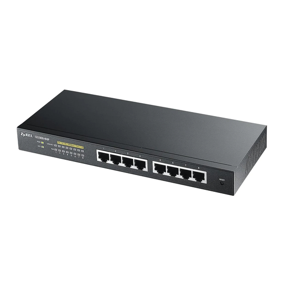
This chapter describes the front panel and rear panel of the Switch and shows you how to make the hardware connections. 3.1 Front Panel Connections The following figures show the front panels of the Switch. Figure 9 Front Panel: GS1900-8 Figure 10 Front Panel: GS1900-8HP Revision A1 Revision B1 Figure 11 Front Panel: GS1900-10HP GS1900 Series User’s Guide... -
Page 26: Ethernet Ports
Chapter 3 Hardware Overview Figure 12 Front Panel: GS1900-16 Figure 13 Front Panel: GS1900-24E Figure 14 Front Panel: GS1900-24 Figure 15 Front Panel: GS1900-24HP Figure 16 Front Panel: GS1900-48 Figure 17 Front Panel: GS1900-48HP 3.1.1 Ethernet Ports The Switch has 1000Base-T auto-negotiating, auto-crossover Ethernet ports. In 10/100/1000 Mbps Gigabit Ethernet, the speed can be 10Mbps, 100 Mbps or 1000 Mbps. -
Page 27: Sfp Slots
Chapter 3 Hardware Overview An auto-negotiating port can detect and adjust to the optimum Ethernet speed (10/100/1000 Mbps) and duplex mode (full duplex or half duplex) of the connected device. An auto-crossover (auto-MDI/MDI-X) port automatically works with a straight-through or crossover Ethernet cable. -
Page 28: Rear Panel
Figure 20 Opening the Transceiver’s Latch Example Pull the transceiver out of the slot. Figure 21 Transceiver Removal Example 3.2 Rear Panel The following figures show the rear panels of the Switch. Figure 22 Rear Panel: GS1900-8 GS1900 Series User’s Guide... - Page 29 Chapter 3 Hardware Overview Figure 23 Rear Panel: GS1900-8HP Revision A1 Revision B1 Figure 24 Rear Panel: GS1900-10HP Figure 25 Rear Panel: GS1900-16 Figure 26 Rear Panel: GS1900-24E Figure 27 Rear Panel: GS1900-24 Figure 28 Rear Panel: GS1900-24HP GS1900 Series User’s Guide...
-
Page 30: Power Connection
Chapter 3 Hardware Overview Figure 29 Rear Panel: GS1900-48 Figure 30 Rear Panel: GS1900-48HP 3.2.1 Power Connection Make sure you are using the correct power source and that no objects obstruct the airflow of the fans. The Switch uses two power supply modules, one of which is redundant, so if one power module fails the system can operate on the remaining module. -
Page 31: Leds
Chapter 3 Hardware Overview 3.3 LEDs After you connect the power to the Switch, view the LEDs to ensure proper functioning of the Switch and as an aid in troubleshooting. Table 3 LED Descriptions COLOR STATUS DESCRIPTION Green The system is turned on. The system is off or has failed. - Page 32 Chapter 3 Hardware Overview Table 4 LED Descriptions (continued)(GS1900-8HP (Revison B1) and GS1900-10HP Only) COLOR STATUS DESCRIPTION Left Amber The link to a 10/100 Mbps Ethernet network is up. Blinking The system is transmitting/receiving to/from a 100/1000 Mbps Fiber network. Green The link to a 1 Gbps Ethernet network is up.
-
Page 33: Zon Utility
H A PT ER ZON Utility This chapter describes the screens for ZON Utility. 4.1 ZyXEL One Network (ZON) Utility Screen ZON Utility is a program designed to help you deploy and manage a network more efficiently. It detects devices automatically and allows you to do basic settings on devices in the network without having to be near it. -
Page 34: The Web Configurator
H A PT ER The Web Configurator 5.1 Overview The Switch Web Configurator allows easy management using an Internet browser. In order to use the Web Configurator, you must: • Use Internet Explorer 7.0 and later or Firefox 1.5 and later •... -
Page 35: Navigating The Web Configurator
Chapter 5 The Web Configurator 5.3 Navigating the Web Configurator The following summarizes how to navigate the web configurator from the Getting Start screen. This guide uses the GS1900-10HP screens as an example. The screens may vary slightly for different models. Figure 33 The Web Configurator’s Main Screen The Web Configurator’s main screen is divided into these parts: •... -
Page 36: Navigation Panel
Chapter 5 The Web Configurator Click OK and confirm at the pop-up screen to complete the task. Click Cancel and confirm at the pop-up screen to discard the changes. Figure 17 Web Configurator: Logout Screen 5.3.2 Navigation Panel Use the menu items on the navigation panel to open screens to configure Switch features. The following sections introduce the Switch’s navigation panel menus and their screens. -
Page 37: Monitor Menu
Chapter 5 The Web Configurator Monitor Menu The monitor menu screens display status and statistics information. Table 7 Monitor Menu Screens Summary FOLDER OR LINK FUNCTION System This link takes you to a screen where you can see general identification information for the Switch. IPv4 This link takes you to a screen where you can see an IPv4 interface and the IPv4 settings on the Switch. -
Page 38: Configuration Menu
Chapter 5 The Web Configurator Table 7 Monitor Menu Screens Summary (continued) FOLDER OR LINK FUNCTION CIST Displays CIST instance status. CIST Port Displays CIST port status. Displays MST instance status. MST Port Displays MST port status. STP Statistics Displays STP statistics. LLDP Displays statistics, remote information, and overloading. - Page 39 Chapter 5 The Web Configurator Table 8 Configuration Menu Screens Summary (continued) FOLDER OR LINK FUNCTION VLAN This link takes you to screens where you can configure VLAN, guest VLAN, and voice VLAN settings. VLAN VLAN Configure VLAN settings. Port Configure port settings.
- Page 40 Chapter 5 The Web Configurator Table 8 Configuration Menu Screens Summary (continued) FOLDER OR LINK FUNCTION MST Port Configure MST port settings. LLDP Configure global, port, local information, MED network policy, and MED port settings. Global Configure global settings. Port Configure port settings.
-
Page 41: Maintenance Menu
Chapter 5 The Web Configurator Table 8 Configuration Menu Screens Summary (continued) FOLDER OR LINK FUNCTION Trap Configure trap settings. Trap Destination Configure trap destination settings. Error Disable This link takes you to a screen where you can configure CPU protection and error disable recovery. -
Page 42: Getting Start
H A PT ER Getting Start 6.1 Overview Use the Getting Start screens to check status information about the Switch. 6.1.1 What You Can Do in this Chapter • The main Getting Start screen (Section 6.2 on page 42) displays the Switch’s general device information, system status, system resource usage, and interface status. -
Page 43: Wizard
Chapter 6 Getting Start Table 10 Getting Start (continued) LABEL DESCRIPTION Device Information System Name This field displays the name used to identify the Switch on any network. Model Name This field displays the model name of this Switch. Revision This field displays the hardware revision number of this Switch. - Page 44 Chapter 6 Getting Start Figure 37 Getting Start > Start up > 1 Step 1 Set up IP Each field is described in the following table. Table 11 Getting Start > Start up > 1 Step 1 Set up IP LABEL DESCRIPTION Host Name...
- Page 45 Chapter 6 Getting Start Figure 38 Getting Start > Start up > 2 Step 2 Set up user name/password Each field is described in the following table. Table 12 Getting Start > Start up > 2 Step 2 Set up user name/password LABEL DESCRIPTION Username...
- Page 46 Chapter 6 Getting Start Each field is described in the following table. Table 13 Getting Start > Start up > 3 Step 3 Finish LABEL DESCRIPTION Host Name This field displays a host name. IP Address The Switch needs an IP address for it to be managed over the network. The factory default IP address is 192.168.1.1.
- Page 47 Chapter 6 Getting Start Each field is described in the following table. Table 14 Getting Start > VLAN > 1 Step 1 Create VLAN LABEL DESCRIPTION Create VLAN ID (1- Type a number between 1 and 4094 to create a VLAN ID. 4094) Edit VLAN ID Select from the drop-box a VLAN ID.
- Page 48 Chapter 6 Getting Start Figure 42 Getting Start > VLAN> 3 Step 3 Finish Each field is described in the following table. Table 16 Getting Start > VLAN > 3 Step 3 Finish LABEL DESCRIPTION Currently VLAN ID This field displays the VLAN identification number. Ports belonging to the specified VLAN tag all outgoing frames transmitted.
- Page 49 Chapter 6 Getting Start Figure 43 Getting Start > QoS > 1 Step 1 QoS (Quality of Service) Each field is described in the following table. Table 17 Getting Start > QoS > 1 Step 1 QoS (Quality ofOf Service) LABEL DESCRIPTION Highest...
- Page 50 Chapter 6 Getting Start Each field is described in the following table. Table 18 Getting Start > QoS > 2 Step 2 Finish LABEL DESCRIPTION Highest Displays summary results. Medium Displays summary results. Displays summary results. Previous Click Previous to show the previous screen. Finish Review the information and click Finish to create the task.
- Page 51 Chapter 6 Getting Start Table 19 Getting Start > Link aggregation > 1 Step 1 Link aggregation LABEL DESCRIPTION Group 8 Click and drag icons located on the left to desired preference. Next Click Next to show the next screen. After clicking Next, the finish screen appears.
-
Page 52: Technical Reference
Technical Reference The appendices provide general information. Some details may not apply to your Switch. -
Page 54: Monitor: System
H A PT ER Monitor: System 7.1 Overview This section provides information for System in Monitor. Use the System screens to view general Switch settings. 7.1.1 What You Can Do in this Chapter • The IP screen (Section 7.2 on page 54) displays IPv4 and IPv6. -
Page 55: Ipv6
Chapter 7 Monitor: System The following table describes the labels in this screen. Table 21 Monitor > System > IP > IPv4 LABEL DESCRIPTION DHCP State This field displays the state of Dynamic Host Configuration Protocol RFC 2131 and RFC 2132 (DHCP). -
Page 56: Information
Chapter 7 Monitor: System Table 22 Monitor > System > IP > IPv6 (continued) LABEL DESCRIPTION DHCPv6 DUID DUID(DHCP Unique Identifier). The DHCP server will provide the IP address based on the DUID information from client. DHCPv6 DNS Primary DNS server IPv6 address form DHCP. server 1 DHCPv6 DNS Secondary DNS server IPv6 address from DHCP. -
Page 57: Monitor: Port
H A PT ER Monitor: Port 8.1 Overview This section provides information for Port in Monitor. Use the Port screens to view general Switch port settings. 8.1.1 What You Can Do in this Chapter • The Port screen (Section 8.2 on page 57) displays status, port counters, and bandwidth utilization. -
Page 58: Port Counters
Chapter 8 Monitor: Port Table 24 Monitor > Port > Port > Status (continued) LABEL DESCRIPTION State This is port admin setting state. Link Status This field displays Up, Down or NotPresent. It displays Up when the port is linked up or Down when it is not. - Page 59 Chapter 8 Monitor: Port Table 25 Monitor > Port > Port > Port Counters (continued) LABEL DESCRIPTION Mode This field displays the mode. Port 1 Interface mib Counters iflnOctets This field displays the iflnOctets. iflnUcastPkts This field displays the iflnUcastPkts. iflnNUcastPkts This field displays the iflnNUcastPkts..
-
Page 60: Bandwidth Utilization
Chapter 8 Monitor: Port Table 25 Monitor > Port > Port > Port Counters (continued) LABEL DESCRIPTION etherStatsPkts256to511Octets This field displays the etherStatsPkts256to511Octets. etherStatsPkts512to1023Octets This field displays the etherStatsPkts512to1023Octets. etherStatsPkts1024to1518Octets This field displays the etherStatsPkts1024to1518Octets. 8.2.3 Bandwidth Utilization Utilization is the percentage of a network's bandwidth that is currently being consumed by network traffic. -
Page 61: Poe
Chapter 8 Monitor: Port 8.3 PoE Note: The PoE function and the following screens are available for models ending in “HP” only. The Switch supports both the IEEE 802.3af Power over Ethernet (PoE) and IEEE 802.3at High Power over Ethernet (PoE) standards. The Switch is Power Sourcing Equipment (PSE) because it provides a source of power via its Ethernet ports, and each device that receives power through an Ethernet port is a Powered Device (PD). -
Page 62: Bandwidth Management
Chapter 8 Monitor: Port Table 27 Monitor > Port > PoE LABEL DESCRIPTION Allocated Power(W) This field displays the total amount of power the Switch has reserved for PoE after negotiating with the connected PoE device(s). Consuming Power (W) can be less than or equal but not more than the Allocated Power (W). -
Page 63: Storm Control
Chapter 8 Monitor: Port Table 28 Monitor > Port > Bandwidth Management > Bandwidth Control (continued) LABEL DESCRIPTION Ingress View the maximum bandwidth allowed in kilobits per second (Kbps) for the incoming RateLimit (Kbps) traffic flow on a port. Egress RateLimit View the maximum bandwidth allowed in kilobits per second (Kbps) for the out-going (Kbps) traffic flow on a port. -
Page 64: Monitor: Vlan
H A PT ER Monitor: VLAN 9.1 Overview This section provides information for VLAN in Monitor. A VLAN (Virtual Local Area Network) allows a physical network to be partitioned into multiple logical networks. Devices on a logical network belong to one group. A device can belong to more than one group. -
Page 65: Port
Chapter 9 Monitor: VLAN Figure 57 Monitor > VLAN > VLAN > VLAN Each field is described in the following table. Table 30 Monitor > VLAN > VLAN > VLAN LABEL DESCRIPTION VLAN VLAN ID This is the VLAN identification number. VLAN Name Displays a descriptive name for the VLAN for identification purposes. -
Page 66: Vlan Port
Chapter 9 Monitor: VLAN Table 31 Monitor > VLAN > VLAN > Port (continued) LABEL DESCRIPTION Accept Frame This field displays the type that is accepted by the frame. Type Specifes the type of frames allowed on a port. Choices are All, Tag Only and Untag Only. -
Page 67: Guest Vlan
Chapter 9 Monitor: VLAN Table 32 Monitor > VLAN > VLAN > VLAN Port (continued) LABEL DESCRIPTION Port Displays the port index value. Membership Displays the status of the VLAN group: Forbidden, Excluded, Tagged or Untagged. 9.3 Guest VLAN When 802.1x port authentication is enabled on the Switch and its ports, clients that do not have the correct credentials are blocked from using the port(s). -
Page 68: Voice Vlan
Chapter 9 Monitor: VLAN Each field is described in the following table. Table 33 Monitor > VLAN > Guest VLAN LABEL DESCRIPTION Global State This field displays the state of global guest VLAN. Port Port This field displays a port number. State This field displays the state of a port. - Page 69 Chapter 9 Monitor: VLAN Table 34 Monitor > VLAN > Voice VLAN (continued) LABEL DESCRIPTION Port This field displays a port number. State This field displays the state of a port. GS1900 Series User’s Guide...
-
Page 70: Monitor: Mac Table
HAPTER Monitor: MAC Table 10.1 Overview This section provides information for MAC Table in Monitor. The MAC Table screen (a MAC table is also known as a filtering database) shows how frames are forwarded or filtered across the Switch’s ports. When a device (which may belong to a VLAN group) sends a packet which is forwarded to a port on the Switch, the MAC address of the device is shown on the Switch’s MAC Table. -
Page 71: What You Can Do In This Chapter
Chapter 10 Monitor: MAC Table 10.1.1 What You Can Do in this Chapter • The MAC Table screen (Section 10.2 on page 71) displays view filter and MAC table of the Switch. 10.2 MAC Table Use this screen to view filter static and MAC table settings. Click Monitor > MAC Table to access this screen. -
Page 72: Monitor: Link Aggregation
HAPTER Monitor: Link Aggregation 11.1 Overview This section provides information for Link Aggregation in Monitor. Link aggregation (trunking) is the grouping of physical ports into one logical higher-capacity link. You may want to trunk ports if for example, it is cheaper to use multiple lower-speed links than to under-utilize a high-speed, but more costly, single-port link. - Page 73 Chapter 11 Monitor: Link Aggregation Each field is described in the following table. Table 36 Monitor > Link Aggregation > LAG LABEL DESCRIPTION Displays the link aggregation status index value. Name This field displays the name. Type This field displays the type. Link Status This field displays the status of the link.
-
Page 74: Monitor: Loop Guard
HAPTER Monitor: Loop Guard 12.1 Overview This section provides information for Loop Guard in Monitor. Loop guard is designed to handle loop problems on the edge of your network. This can occur when a port is connected to a Switch that is in a loop state. Loop state occurs as a result of human error. It happens when two ports on a switch are connected with the same cable. -
Page 75: What You Can Do In This Chapter
Chapter 12 Monitor: Loop Guard Figure 67 Loop Guard - Probe Packet The Switch also shuts down port N if the probe packet returns to switch A on any other port. In other words loop guard also protects against standard network loops. The following figure illustrates three switches forming a loop. - Page 76 Chapter 12 Monitor: Loop Guard Figure 69 Monitor > Loop Guard Each field is described in the following table. Table 37 Monitor > Loop Guard LABEL DESCRIPTION Loop Guard Status Port This field displays a port number. Status This field displays the status. Time Left (sec) This field displays the amount of time left in seconds.
-
Page 77: Monitor: Multicast
HAPTER Monitor: Multicast 13.1 Overview This section provides information for Multicast in Monitor. Traditionally, IP packets are transmitted in one of either two ways - Unicast (1 sender to 1 recipient) or Broadcast (1 sender to everybody on the network). Multicast delivers IP packets to just a group of hosts on the network. -
Page 78: Statistics
Chapter 13 Monitor: Multicast Each field is described in the following table. Table 38 Monitor > Multicast > IGMP > Vlan LABEL DESCRIPTION VLAN ID Displays the identification for the VLAN. Operate Status Displays the status of the operation. Router Ports Auto Displays whether the router ports are auto learn or not. -
Page 79: Group
Chapter 13 Monitor: Multicast Each field is described in the following table. Table 39 Monitor > Multicast > IGMP > Statistics LABEL DESCRIPTION Clear Click Clear to reset the fields to the factory defaults. Refresh Click Refresh to reload the page. Port This field displays a port number. -
Page 80: Router
Chapter 13 Monitor: Multicast Figure 73 Monitor > Multicast > IGMP > Group Each field is described in the following table. Table 40 Monitor > Multicast > IGMP > Group LABEL DESCRIPTION Clear Click Clear to delete the dynamic groups. Refresh Click Refresh to reload the page. -
Page 81: Monitor: Spanning Tree
HAPTER Monitor: Spanning Tree 14.1 Overview This section provides information for Spanning Tree in Monitor. The Switch supports Spanning Tree Protocol (STP), Common and Internal Spanning Tree (CIST), and Multiple Spanning Tree (MST). 14.1.1 What You Can Do in this Chapter •... -
Page 82: Cist Port
Chapter 14 Monitor: Spanning Tree Each field is described in the following table. Table 42 Monitor > Spanning Tree > CIST LABEL DESCRIPTION State This field displays the state. Bridge This is the unique identifier for this bridge, consisting of the bridge priority plus the MAC Indentifier address. -
Page 83: Mst
Chapter 14 Monitor: Spanning Tree Each field is described in the following table. Table 43 Monitor > Spanning Tree > CIST Port LABEL DESCRIPTION Port This field displays the port number. Indentifier This field displays the identifier (in priority / port number). (Priority / Port Id) External Path Cost Path cost is the cost of transmitting a frame on to a LAN through that port. -
Page 84: Mst Port
Chapter 14 Monitor: Spanning Tree Each field is described in the following table. Table 44 Monitor > Spanning Tree > MST LABEL DESCRIPTION MST ID This is the unique identifier for this MST. Select a number from the drop-down menu to display results. State This field displays the state. -
Page 85: Stp Statistics
Chapter 14 Monitor: Spanning Tree Table 45 Monitor > Spanning Tree > MST Port (continued) LABEL DESCRIPTION Indentifier (Priority This field displays the identifier (in priority / port number). / Port Id) Internal Path Path cost is the cost of transmitting a frame on to a LAN through that port. It is Cost(Operation) recommended to assign this value according to the speed of the bridge. - Page 86 Chapter 14 Monitor: Spanning Tree Each field is described in the following table. Table 46 Monitor > Spanning Tree > STP Statistics LABEL DESCRIPTION Port This field displays the port number. Configuration This field displays the configuration BDPUs received. BDPUs Received TCN BDPUs This field displays the TCN BDPUs received.
-
Page 87: Monitor: Lldp
HAPTER Monitor: LLDP 15.1 Overview This section provides information for LLDP in Monitor. Link Layer Discovery Protocol (LLDP), defined as IEEE 802.1ab, enables LAN devices that support LLDP to exchange their configured settings. This helps eliminate configuration mismatch issues. 15.1.1 What You Can Do in this Chapter •... -
Page 88: Remote Information
Chapter 15 Monitor: LLDP Each field is described in the following table. Table 47 Monitor > LLDP > Statistics LABEL DESCRIPTION Clear Click Clear to clear statistics. Refresh Click Refresh to reload the page. Global Statistics Insertions This field displays the number of insertions. Deletions This field displays the number of deletions. -
Page 89: Overloading
Chapter 15 Monitor: LLDP Table 48 Monitor > LLDP > Remote Information (continued) LABEL DESCRIPTION Action Detail Click Detail to show more information about this entry. Delete Click Delete to remove the entry. 15.2.3 Overloading Use this screen to view the Switch’s LLDP port overloading. Click Monitor > LLDP > Overloading to access this screen. -
Page 90: Monitor: Security
HAPTER Monitor: Security 16.1 Overview This section provides information for Security in Monitor. This link takes you to a screen where you can view the settings or traffic statistics which contain detailed information about specific activities. 16.1.1 What You Can Do in this Chapter •... -
Page 91: Port
Chapter 16 Monitor: Security Each field is described in the following table. Table 50 Monitor > Security > Port Security LABEL DESCRIPTION Global Status This field displays the status of global control information. Port Port This field displays a port number. Status This field displays the status of port based control information. -
Page 92: Authenticated Hosts
Chapter 16 Monitor: Security 16.3.2 Authenticated Hosts Use this screen to view the Switch’s 802.1x security authenticated host status. Click Monitor > Security > 802.1X > Authenticated Hosts to access this screen. Figure 85 Monitor > Security > 802.1X> Authenticated Hosts Each field is described in the following table. -
Page 93: Monitor: Management
HAPTER Monitor: Management 17.1 Overview This section provides information for Management in Monitor. This chapter describes how to view management settings on the Switch. 17.1.1 What You Can Do in this Chapter • The Syslog screen (Section 17.2 on page 93) displays logging filter select and shows system log. -
Page 94: Error Disable
Chapter 17 Monitor: Management Each field is described in the following table. Table 53 Monitor > Management > Syslog LABEL DESCRIPTION Logging Filter Select Target Select Buffered or Flash. Buffered: Login saved to temporary memory. Flash: Login saved to permanent memory. Severity This field displays two options: Available and Acting. - Page 95 Chapter 17 Monitor: Management Figure 87 Monitor > Management > Error Disable Each field is described in the following table. Table 54 Monitor > Management > Error Disable LABEL DESCRIPTION Global Recovery View the number of seconds (from 30 to 2592000) for the time interval of the recovery. Interval Error Disabled This field displays the supported features that allow the Switch to shut down a port or...
-
Page 96: Configuration: System
HAPTER Configuration: System 18.1 Overview This section provides information for System in Configuration. 18.1.1 What You Can Do in this Chapter • The IP screen (Section 18.2 on page 96) displays IPv4 and IPv6 settings. • The Time screen (Section 18.3 on page 98) displays the system time and SNTP settings. -
Page 97: The Ipv6 Screen
Chapter 18 Configuration: System The following table describes the labels in this screen. Table 55 Configuration > System > IP > IPv4 LABEL DESCRIPTION IPv4 Address Mode Select Static to define the IPv4 network properties or DHCP to allow the device to define the properties. -
Page 98: Time
Chapter 18 Configuration: System Table 56 Configuration > System > IP > IPv6 (continued) LABEL DESCRIPTION IPv6 Address Enter the IPv6 address of the Switch in the IP domain. Gateway Enter the IPv6 address of the default outgoing gateway. Apply Click Apply to save the changes. -
Page 99: The Sntp Server Screen
Chapter 18 Configuration: System Table 57 Configuration > System > Time (continued) LABEL DESCRIPTION Daylight Saving Enter the daylight saving time offset value in minutes. Time Offset Start Date Select the start date of the daylight saving time period from the dropdown lists. End Date Select the end date of the daylight saving time period from the dropdown lists. - Page 100 Chapter 18 Configuration: System Figure 92 Configuration > System > System Information The following table describes the labels in this screen. Table 59 Configuration > System > System Information LABEL DESCRIPTION System Information System Name Enter the descriptive name of the Switch for identification purposes. System Location Enter the geographic location of the Switch for identification purposes.
-
Page 101: Configuration: Port
HAPTER Configuration: Port 19.1 Overview This section provides information for Port in Configuration. 19.1.1 What You Can Do in this Chapter • The Port screen (Section 19.2 on page 101) displays general port settings. • The EEE screen (Section 19.3 on page 103) displays the port EEE settings. -
Page 102: The Port Edit Screen
Chapter 19 Configuration: Port Table 60 Configuration > Port > Port > Port (continued) LABEL DESCRIPTION Port Name Displays a descriptive name that identifies this port. The length of the name can be up to 32 alpha-numerical characters. Note: Due to space limitations, the port name may be truncated in some web configurator screens. -
Page 103: Eee
Chapter 19 Configuration: Port The following table describes the labels in this screen. Table 61 Configuration > Port > Port > Edit LABEL DESCRIPTION Port Edit Port List Displays the list of port index numbers that are being configured. Port Name Enter a descriptive name that identifies this port. -
Page 104: The Eee Edit Screen
Chapter 19 Configuration: Port The following table describes the labels in this screen. Table 62 Configuration > Port > EEE > EEE LABEL DESCRIPTION Edit Select this check box to configure the properties of a port. Click the Edit button change the properties of the port. -
Page 105: The Global Screen
Chapter 19 Configuration: Port 19.4.1 The Global Screen In the navigation panel, click Configuration > Port > PoE > Global to display the screen as shown. Use this screen to configure Power over Ethernet (PoE) global settings. Figure 97 Configuration > Port > PoE > Global The following table describes the labels in this screen. - Page 106 Chapter 19 Configuration: Port Figure 98 Configuration > Port > PoE > Port The following table describes the labels in this screen. Table 65 Configuration > Port > PoE > Port LABEL DESCRIPTION Edit Select one or more ports in the first column of the table and click this to configure PoE settings for the ports.
-
Page 107: The Poe Edit Screen
Chapter 19 Configuration: Port Table 65 Configuration > Port > PoE > Port (continued) LABEL DESCRIPTION Wide Range This field is available on GS1900-8HP (Revision B1) and GS1900-10HP only. Detection This shows whether the Switch enables a wider detection range for the PD or not. The Switch detects whether a connected device is a powered device or not before supplying power to the port. - Page 108 Chapter 19 Configuration: Port Table 66 Configuration > Port > PoE > Port > Edit (continued) LABEL DESCRIPTION PD Priority This field is not available for the SFP or SFP+ ports. When the total power requested by the PDs exceeds the total PoE power budget on the Switch, you can set the PD priority to allow the Switch to provide power to ports with higher priority.
-
Page 109: Bandwidth Management
Chapter 19 Configuration: Port 19.5 Bandwidth Management Bandwidth management means defining a maximum allowable bandwidth for incoming and/or out- going traffic flows on a port. 19.5.1 The Bandwidth Control Screen Use this screen to view Egress Bandwidth Management settings and select ports for configuration. Click Configuration >... -
Page 110: The Port Rate Edit Screen
Chapter 19 Configuration: Port Table 67 Configuration > Port > Bandwidth Management > Bandwidth Control (continued) LABEL DESCRIPTION Ingress Rate Displays the maximum bandwidth allowed in kilobits per second (Kbps) for the incoming Limit (Kbps) traffic flow on a port. Egress Rate Displays the maximum bandwidth allowed in kilobits per second (Kbps) for the outgoing Limit (Kbps) -
Page 111: Storm Control
Chapter 19 Configuration: Port 19.6 Storm Control Broadcast storm control limits the number of broadcast, multicast and destination lookup failure (DLF) packets the Switch receives per second on the ports. When the maximum number of allowable broadcast, multicast and/or DLF packets is reached per second, the subsequent packets are discarded. -
Page 112: The Port Edit Screen
Chapter 19 Configuration: Port 19.6.2 The Port Edit Screen Use this screen to configure Storm Control settings for individual ports. Click Configuration > Port > Storm Control > Port > Edit to open this screen. Figure 103 Configuration > Port > Storm Control > Port > Edit The following table describes the labels in this screen. -
Page 113: Configuration: Vlan
HAPTER Configuration: VLAN 20.1 Overview This section provides information for VLAN in Configuration. A VLAN (Virtual Local Area Network) allows a physical network to be partitioned into multiple logical networks. Devices on a logical network belong to one group. A device can belong to more than one group. -
Page 114: Vlan
Chapter 20 Configuration: VLAN 20.2 VLAN Use this screen to view and configure VLAN settings. 20.2.1 The VLAN Screen Use this screen to view VLAN settings. Click Configuration > VLAN > VLAN > VLAN to open this screen. Figure 104 Configuration > VLAN > VLAN > VLAN The following table describes the labels in this screen. -
Page 115: The Port Screen
Chapter 20 Configuration: VLAN The following table describes the labels in this screen. Table 72 Configuration > VLAN > VLAN > VLAN > Add LABEL DESCRIPTION VLAN VLAN List Primary private VLANs can associate with several (secondary) Community private VLANs and up to one (secondary) Isolated private VLAN. -
Page 116: The Port Edit Screen
Chapter 20 Configuration: VLAN The following table describes the labels in this screen. Table 73 Configuration > VLAN > VLAN > Port LABEL DESCRIPTION Port Edit Select this check box to configure the properties of a port. Click the Edit button change the properties of the port. -
Page 117: The Vlan Port Screen
Chapter 20 Configuration: VLAN Table 74 Configuration > VLAN > VLAN > Port > Edit (continued) LABEL DESCRIPTION Accepted Type Select All from the drop-down list box to accept all untagged or tagged frames on this port. This is the default setting. Select Tag Only to accept only tagged frames on this port. - Page 118 Chapter 20 Configuration: VLAN Figure 108 Configuration > VLAN > VLAN > VLAN Port The following table describes the labels in this screen. Table 75 Configuration > VLAN > VLAN > VLAN Port LABEL DESCRIPTION VLAN Port VLAN ID Select the ID of the VLAN you want to configure. Port Displays the port index value.
-
Page 119: Guest Vlan
Chapter 20 Configuration: VLAN 20.3 Guest VLAN When 802.1x port authentication is enabled on the Switch and its ports, clients that do not have the correct credentials are blocked from using the port(s). You can configure your Switch to have one VLAN that acts as a guest VLAN. -
Page 120: The Port Screen
Chapter 20 Configuration: VLAN Table 76 Configuration > VLAN > Guest VLAN > Global (continued) LABEL DESCRIPTION Guest VLAN ID Enter the global guest VLAN ID. Apply Click Apply to save the changes. Cancel Click Cancel to discard the changes. 20.3.2 The Port Screen Use this screen to view the Guest VLAN port settings and select VLAN port(s) for configuration. -
Page 121: Voice Vlan
Chapter 20 Configuration: VLAN Figure 112 Configuration > VLAN > Guest VLAN > Port > Edit The following table describes the labels in this screen. Table 78 Configuration > VLAN > Guest VLAN > Port > Edit LABEL DESCRIPTION Port Port List Displays the list of port index numbers that are being configured. -
Page 122: The Oui Screen
Chapter 20 Configuration: VLAN Figure 113 Configuration > VLAN > Voice VLAN > Global The following table describes the labels in this screen. Table 79 Configuration > VLAN > Voice VLAN > Global LABEL DESCRIPTION Global State Select Enable to activate the global voice VLAN feature. Voice VLAN ID Enter the global voice VLAN ID. -
Page 123: The Oui Add/Edit Screen
Chapter 20 Configuration: VLAN Figure 114 Configuration > VLAN > Voice VLAN > OUI The following table describes the labels in this screen. Table 80 Configuration > VLAN > Voice VLAN > OUI LABEL DESCRIPTION Click Add to create a new OUI entry. OUI Address Displays an OUI address. -
Page 124: The Port Screen
Chapter 20 Configuration: VLAN The following table describes the labels in this screen. Table 81 Configuration > VLAN > Voice VLAN > OUI > Add/Edit LABEL DESCRIPTION OUI Address Enter an OUI address. A telephony OUI address is a globally unique identifier assigned to a vendor by IEEE. -
Page 125: The Port Edit Screen
Chapter 20 Configuration: VLAN Table 82 Configuration > VLAN > Voice VLAN > Port (continued) LABEL DESCRIPTION Port Displays the port index value. State Displays the Voice VLAN port security mode state. When the function is enabled, all non- telephonic MAC addresses in the Voice VLAN will be blocked for 10 seconds. Possible port modes are: •... -
Page 126: Configuration: Mac Table
HAPTER Configuration: MAC Table 21.1 Overview This section provides information for MAC Table in Configuration. The MAC Table screen (a MAC table is also known as a filtering database) shows how frames are forwarded or filtered across the Switch’s ports. When a device (which may belong to a VLAN group) sends a packet which is forwarded to a port on the Switch, the MAC address of the device is shown on the Switch’s MAC Table. -
Page 127: The Static Mac Add Screen
Chapter 21 Configuration: MAC Table Table 84 Configuration > MAC Table > Static MAC (continued) LABEL DESCRIPTION VLAN Displays the VLAN group to which this frame belongs. Port Displays the port from which the above MAC address was learned. Action Click Delete to remove the MAC address. -
Page 128: The Filtering Mac Add Screen
Chapter 21 Configuration: MAC Table The following table describes the labels in this screen. Table 86 Configuration > MAC Table > Filtering MAC LABEL DESCRIPTION MAC Filtering Click Add to create a new Filtering MAC entry. MAC Address Displays the filtering object MAC address from which this incoming frame came. VLAN Displays the VLAN group to which this frame belongs. - Page 129 Chapter 21 Configuration: MAC Table Figure 122 Configuration > MAC Table > Dynamic Age The following table describes the labels in this screen. Table 88 Configuration > Dynamic Age LABEL DESCRIPTION Dynamic MAC Age Aging Time Enter the aging time of the MAC address. The value can be between 10 and 630 seconds. Apply Click Apply to save the changes.
-
Page 130: Configuration: Link Aggregation
HAPTER Configuration: Link Aggregation 22.1 Overview This section provides information for Link Aggregation in Configuration. This chapter shows you how to logically aggregate physical links to form one logical, higher bandwidth link. 22.1.1 What You Can Do in this Chapter The Link Aggregation screen (Section 22.2 on page 130) displays global, LAG management, LAG... -
Page 131: The Lag Management Screen
Chapter 22 Configuration: Link Aggregation Figure 123 Configuration > Link Aggregation > Global The following table describes the labels in this screen. Table 89 Configuration > Link Aggregation > Global LABEL DESCRIPTION Global LACP State Select Enable to activate the link aggregation control protocol. LACP System LACP system priority is a number between 1 and 65,535. -
Page 132: The Lag Add Screen
Chapter 22 Configuration: Link Aggregation The following table describes the labels in this screen. Table 90 Configuration > Link Aggregation > LAG Management LABEL DESCRIPTION LAG Management Click Add to create a new LAG Management entry. Displays the link aggregation group (LAG), that is, one logical link containing multiple ports. Name Displays the name of the link aggregation group. -
Page 133: The Lag Port Screen
Chapter 22 Configuration: Link Aggregation The following table describes the labels in this screen. Table 91 Configuration > Link Aggregation > LAG Management > Add LABEL DESCRIPTION LAG Management Select the link aggregation group (LAG). Name Enter the name of this entry. Type Select Static or LACP. -
Page 134: The Lag Port Edit Screen
Chapter 22 Configuration: Link Aggregation 22.2.5 The LAG Port Edit Screen Use this screen to edit a LAG port. Click Configuration > Link Aggregation > LAG Port > Edit to open this screen. Figure 127 Configuration > Link Aggregation > LAG Port > Edit The following table describes the labels in this screen. -
Page 135: The Lacp Port Edit Screen
Chapter 22 Configuration: Link Aggregation Figure 128 Configuration > Link Aggregation > LACP Port The following table describes the labels in this screen. Table 94 Configuration > Link Aggregation > LACP Port LABEL DESCRIPTION LACP Port Edit Select this check box to configure the properties of a port. Click the Edit button change the properties of the port. - Page 136 Chapter 22 Configuration: Link Aggregation The following table describes the labels in this screen. Table 95 Configuration > Link Aggregation > LACP Port > Edit LABEL DESCRIPTION LACP Port Port List Displays the list of port index numbers to be configured. Priority Enter a value for the port priority.
-
Page 137: Configuration: Loop Guard
HAPTER Configuration: Loop Guard 23.1 Overview This section provides information for Loop Guard in Configuration. This chapter shows you how to configure the Switch to guard against loops on the edge of your network. 23.2 Loop Guard Loop guard allows you to configure the Switch to shut down a port if it detects that packets sent out on that port loop back to the Switch. -
Page 138: The Loop Guard Port
Chapter 23 Configuration: Loop Guard Table 96 Configuration > Loop Guard (continued) LABEL DESCRIPTION Recovery Time Enter the period (in seconds) for which a port will be kept disabled in the event of a loop is detected (and the port action shuts down the port). Apply Click Apply to save the changes. - Page 139 Chapter 23 Configuration: Loop Guard Figure 132 Configuration > Loop Guard > Port > Edit The following table describes the labels in this screen. Table 98 Configuration > Loop Guard > Port > Edit LABEL DESCRIPTION Port Port List Displays the list of port index numbers to be configured. State Select Enable to use the Admin Enabled feature.
-
Page 140: Configuration: Mirror
HAPTER Configuration: Mirror 24.1 Overview This section provides information for Mirror in Configuration. 24.2 Mirror Port mirroring allows you to copy a traffic flow to a monitor port (the port you copy the traffic to) in order that you can examine the traffic from the monitor port without interference. The Switch supports local port mirroring. - Page 141 Chapter 24 Configuration: Mirror The following table describes the labels in this screen. Table 99 Configuration > Mirror LABEL DESCRIPTION Mirror Mirroring Select Enable to activate port mirroring on the Switch or Disable to disable the feature. Monitor Port The monitor port is the port you copy the traffic to in order to examine it in more detail without interfering with the traffic flow on the original port(s).
-
Page 142: Configuration: Multicast
HAPTER Configuration: Multicast 25.1 Overview This section provides information for Multicast in Configuration. Traditionally, IP packets are transmitted in one of either two ways - Unicast (1 sender to 1 recipient) or Broadcast (1 sender to everybody on the network). Multicast delivers IP packets to just a group of hosts on the network. -
Page 143: The Vlan Screen
Chapter 25 Configuration: Multicast Table 100 Configuration > Multicast > IGMP (continued) LABEL DESCRIPTION Snooping Select v2 or v3 depending on the snooping version you require. Version Unknown Select to send the IPv4 unknown multicast frame to the router port. The following options Multicast Action are available: •... -
Page 144: The Edit Igmp Screen
Chapter 25 Configuration: Multicast Table 101 Configuration > Multicast > IGMP > VLAN (continued) LABEL DESCRIPTION State Displays the switch current VLAN querier entry as Enable or Disable. Version Displays the switch current VLAN querier entry version. 25.2.3 The Edit IGMP Screen Use this screen to configure the IGMP VLAN settings. -
Page 145: The Router Port Screen
Chapter 25 Configuration: Multicast Table 102 Configuration > Multicast > IGMP > VLAN > Modify (continued) LABEL DESCRIPTION Last Member Query Count Enter the number of queries. Interval (sec) Enter the amount of time (in seconds) between the IGMP group-specific queries sent by an upstream port when an IGMP Done message is received. -
Page 146: The Profile Screen
Chapter 25 Configuration: Multicast Figure 138 Configuration > Multicast > IGMP > Router Port > Add/Modify The following table describes the labels in this screen. Table 104 Configuration > Multicast > IGMP > Router Port > Add/Modify LABEL DESCRIPTION IGMP Router Edit VLAN List Enter the static VLAN IDs (valid range for each ID value is between 1 and 4094). -
Page 147: The Add/Edit Profile Screen
Chapter 25 Configuration: Multicast Figure 139 Configuration > Multicast > IGMP > Profile The following table describes the labels in this screen. Table 105 Configuration > Multicast > IGMP > Profile LABEL DESCRIPTION IGMP Profile Click Add to create a new IGMP Profile entry. Profile Displays the Profile index number. -
Page 148: The Throttling Screen
Chapter 25 Configuration: Multicast Table 106 Configuration > Multicast > IGMP > Profile > Add/Edit (continued) LABEL DESCRIPTION Group To Enter the profile end group IP address. Match Action Select the action of the profile as to be Permit or Deny. Apply Click Apply to save the changes. - Page 149 Chapter 25 Configuration: Multicast Figure 142 Configuration > Multicast > IGMP > Throttling > Add/Edit The following table describes the labels in this screen. Table 108 Configuration > Multicast > IGMP > Throttling > Add/Edit LABEL DESCRIPTION IGMP Port Throttling Port List Enter the port index value(s).
-
Page 150: Configuration: Spanning Tree
HAPTER Configuration: Spanning Tree 26.1 Overview This section provides information for Spanning Tree in Configuration. The Switch supports Spanning Tree Protocol (STP), Rapid Spanning Tree Protocol (RSTP) and Multiple Spanning Tree Protocol (MSTP) as defined in the following standards. • IEEE 802.1D Spanning Tree Protocol •... -
Page 151: The Stp Port Screen
Chapter 26 Configuration: Spanning Tree Figure 143 Configuration > Spanning Tree The following table describes the labels in this screen. Table 109 Configuration > Spanning Tree LABEL DESCRIPTION Global State Select to Enable or Disable the Spanning-Tree function. BPDU Forward Select the bridge protocol data units forward (BPDU) option to be Flooding or Filtering. -
Page 152: The Stp Port Edit Screen
Chapter 26 Configuration: Spanning Tree Figure 144 Configuration > Spanning Tree > STP Port The following table describes the labels in this screen. Table 110 Configuration > Spanning Tree > STP Port LABEL DESCRIPTION STP Port Edit Select this check box to configure the properties of a port. Click the Edit button change the properties of the port. -
Page 153: The Cist Screen
Chapter 26 Configuration: Spanning Tree Figure 145 Configuration > Spanning Tree > STP Port > Edit The following table describes the labels in this screen. Table 111 Configuration > Spanning Tree > STP Port > Edit LABEL DESCRIPTION STP Port Port List Enter the index number of the STP port(s). - Page 154 Chapter 26 Configuration: Spanning Tree Figure 146 Configuration > Spanning Tree > CIST The following table describes the labels in this screen. Table 112 Configuration > Spanning Tree > CIST LABEL DESCRIPTION CIST Instance Priority Configure priority of CIST bridge ID. Priority is part of bridge ID, used for CIST root bridge selection.
-
Page 155: The Cist Port Screen
Chapter 26 Configuration: Spanning Tree 26.2.5 The CIST Port Screen Use this screen to view the CIST Port settings. Click Configuration > Spanning Tree > CIST Port to open this screen. Figure 147 Configuration > Spanning Tree > CIST Port The following table describes the labels in this screen. -
Page 156: The Mst Screen
Chapter 26 Configuration: Spanning Tree Figure 148 Configuration > Spanning Tree > CIST Port > Edit The following table describes the labels in this screen. Table 114 Configuration > Spanning Tree > CIST Port > Edit LABEL DESCRIPTION STP CIST Port Port List Enter the index number of the STP port(s). -
Page 157: The Add/Modify Mst Screen
Chapter 26 Configuration: Spanning Tree Table 115 Configuration > Spanning Tree > MST (continued) LABEL DESCRIPTION VLAN Count Displays the VLAN count. Priority Displays the priority for each port here. Action Edit Click Edit to make changes to the entry. Delete Click Delete to remove the entry. -
Page 158: The Mst Port Edit Screen
Chapter 26 Configuration: Spanning Tree Figure 151 Configuration > Spanning Tree > MST Port The following table describes the labels in this screen. Table 117 Configuration > Spanning Tree > MST Port LABEL DESCRIPTION MST Port MST ID Select the MST port ID number from the dropdown list. Edit Select this check box to configure the properties of MST ID. - Page 159 Chapter 26 Configuration: Spanning Tree Figure 152 Configuration > Spanning Tree > MST Port > Edit The following table describes the labels in this screen. Table 118 Configuration > Spanning Tree > MST Port > Edit LABEL DESCRIPTION STP MST Port MST ID Displays the MST ID number.
-
Page 160: Configuration: Lldp
HAPTER Configuration: LLDP 27.1 Overview This section provides information for LLDP in Configuration. Use the Link Layer Discovery Protocol (LLDP) screens to configure LLDP Switch settings. 27.2 LLDP This page allows the user to inspect and configure the current LLDP port settings. 27.2.1 The Global Screen Use this screen to configure the Global settings. -
Page 161: The Port Screen
Chapter 27 Configuration: LLDP Table 119 Configuration > LLDP > Global (continued) LABEL DESCRIPTION Transmission Enter the transmission interval value. Interval The switch periodically transmits LLDP frames to its neighbors for having the network discovery information up-to-date. The interval between each LLDP frame is determined by the Tx Interval value. -
Page 162: The Port Edit Screen
Chapter 27 Configuration: LLDP Figure 154 Configuration > LLDP > Port The following table describes the labels in this screen. Table 120 Configuration > LLDP > Port LABEL DESCRIPTION LLDP VLAN Edit Select this check box to configure the properties of a port. Click the Edit button change the properties of the port. -
Page 163: The Local Information Screen
Chapter 27 Configuration: LLDP Figure 155 Configuration > LLDP > Port > Edit The following table describes the labels in this screen. Table 121 Configuration > LLDP > Port > Edit LABEL DESCRIPTION LLDP Port Port List Displays the index number of the LLDP port(s). Mode Select the mode of the LLDP port as Disable, Tx Only, Rx Only, or Tx &... - Page 164 Chapter 27 Configuration: LLDP Figure 156 Configuration > LLDP > Local Information The following table describes the labels in this screen. Table 122 Configuration > LLDP > Local Information LABEL DESCRIPTION Local Device Summary Chassis ID Displays the chassis ID subtype. Subtype Chassis ID The Chassis ID is the identification of the neighbor's LLDP frames.
-
Page 165: The Local Information Edit Screen
Chapter 27 Configuration: LLDP Table 122 Configuration > LLDP > Local Information (continued) LABEL DESCRIPTION Capabilities Capabilities Supported describes the neighbor unit's capabilities. The possible Supported capabilities are: 1. Other 2. Repeater 3. Bridge 4. WLAN Access Point 5. Router 6. - Page 166 Chapter 27 Configuration: LLDP Figure 157 Configuration > LLDP > Local Information > Edit The following table describes the labels in this screen. Table 123 Configuration > LLDP > Local Information > Edit LABEL DESCRIPTION MED Port Location Port List Displays the index number of the LLDP port(s).
- Page 167 Chapter 27 Configuration: LLDP Table 123 Configuration > LLDP > Local Information > Edit (continued) LABEL DESCRIPTION Location Coordinates Latitude Latitude SHOULD be normalized to within 0-90 degrees with a maximum of 4 digits. It is possible to specify the direction to either North of the equator or South of the equator.
-
Page 168: The Med Network Policy Screen
Chapter 27 Configuration: LLDP Table 123 Configuration > LLDP > Local Information > Edit (continued) LABEL DESCRIPTION Location ECS Emergency Call Service (e.g. E911 and others), such as defined by TIA or NENA. ELIN Emergency Call Service ELIN identifier data format is defined to carry the ELIN identifier as used during emergency call setup to a traditional CAMA or ISDN trunk-based PSAP. - Page 169 Chapter 27 Configuration: LLDP Figure 159 Configuration > LLDP > MED Network Policy > Add/Edit The following table describes the labels in this screen. Table 125 Configuration > LLDP > MED Network Policy > Edit LABEL DESCRIPTION MED Port Location Edit Select the index of network policy Application Select the Application type indicating the primary function of the application(s) defined for...
-
Page 170: The Med Port Screen
Chapter 27 Configuration: LLDP Table 125 Configuration > LLDP > MED Network Policy > Edit (continued) LABEL DESCRIPTION VLAN ID Enter the VLAN ID (VID) for the port as defined in IEEE 802.1Q-2003. A value of 1 through 4094 is used to define a valid VLAN ID. A value of 0 (Priority Tagged) is used if the device is using priority tagged frames as defined by IEEE 802.1Q-2003, meaning that only the IEEE 802.1D priority level is significant and the default PVID of the ingress port is used instead. -
Page 171: The Med Port Add/Edit Screen
Chapter 27 Configuration: LLDP Table 126 Configuration > LLDP > MED Port (continued) LABEL DESCRIPTION Location Displays the Location value. Displays the PoE value. Inventory Displays the Inventory value. 27.2.9 The MED Port Add/Edit Screen Use this screen to configure the MED Port Edit settings. Click Configuration > LLDP > MED Port >... - Page 172 Chapter 27 Configuration: LLDP Table 127 Configuration > LLDP > MED Port > Edit (continued) LABEL DESCRIPTION Apply Click Apply to save the changes. Cancel Click Cancel to discard the changes. GS1900 Series User’s Guide...
-
Page 173: Configuration: Qos
HAPTER Configuration: QoS 28.1 Overview This section provides information for QoS (Quality of Service) in Configuration. 28.2 General Quality of Service (QoS) refers to both a network's ability to deliver data with minimum delay, and the networking methods used to control the use of bandwidth. Without QoS, all traffic data is equally likely to be dropped when the network is congested. -
Page 174: The Port Edit Screen
Chapter 28 Configuration: QoS The following table describes the labels in this screen. Table 128 Configuration > QoS > General LABEL DESCRIPTION QoS Port Edit Select this check box to configure the properties of a port. Click the Edit button change the properties of the port. -
Page 175: The Queue Screen
Chapter 28 Configuration: QoS 28.2.3 The Queue Screen Use this screen to view the Queue settings. Click Configuration > QoS > General > Queue to open this screen. Figure 164 Configuration > QoS > General > Queue The following table describes the labels in this screen. Table 130 Configuration >... - Page 176 Chapter 28 Configuration: QoS Figure 165 Configuration > QoS > General > CoS Mapping The following table describes the labels in this screen. Table 131 Configuration > QoS > General > CoS Mapping LABEL DESCRIPTION CoS to Queue Mapping Class of Service (CoS) Displays a listing of the CoS, range: 0 - 7.
-
Page 177: The Dscp Mapping Screen
Chapter 28 Configuration: QoS 28.2.5 The DSCP Mapping Screen Use this screen to configure the DSCP Mapping settings. Click Configuration > QoS > General > DSCP Mapping to open this screen. Figure 166 Configuration > QoS > General > DSCP Mapping The following table describes the labels in this screen. -
Page 178: The Ip Precedence Mapping Screen
Chapter 28 Configuration: QoS 28.2.6 The IP Precedence Mapping Screen Use this screen to configure the IP Precedence Mapping settings. Click Configuration > QoS > General > IP Precedence Mapping to open this screen. Figure 167 Configuration > QoS > General > IP Precedence Mapping The following table describes the labels in this screen. -
Page 179: Trust Mode
Chapter 28 Configuration: QoS Table 133 Configuration > QoS > General > IP Precedence Mapping (continued) LABEL DESCRIPTION Queue to IP Precedence Mapping Queue ID Displays a listing of Queue ID, range: 0 - 7. IP Precedence Click the drop-down menu to map a Queue ID to a specific IP precedence. (0-7) Apply Click Apply to save the changes. -
Page 180: The Trust Mode Edit Screen
Chapter 28 Configuration: QoS Figure 169 Configuration > QoS > Trust Mode > Port The following table describes the labels in this screen. Table 135 Configuration > QoS > Trust Mode > Port LABEL DESCRIPTION QoS Port Edit Select this check box to configure the properties of a port. Click the Edit button change the properties of the port. - Page 181 Chapter 28 Configuration: QoS Figure 170 Configuration > QoS > Trust Mode > Port > Edit The following table describes the labels in this screen. Table 136 Configuration > QoS > Trust Mode > Port > Edit LABEL DESCRIPTION QoS Port Trust Edit Port List Displays the port index value(s).
-
Page 182: Configuration: Security
HAPTER Configuration: Security 29.1 Overview This section provides information for Security in Configuration. 29.2 Port Security 29.2.1 The Global Screen Use this screen to view the Global settings. Click Configuration > Security > Port Security to open this screen. Figure 171 Configuration > Security > Port Security The following table describes the labels in this screen. -
Page 183: The Port Edit Screen
Chapter 29 Configuration: Security Figure 172 Configuration > Security > Port Security > Port The following table describes the labels in this screen. Table 138 Configuration > Security > Port Security > Port LABEL DESCRIPTION Port Edit Click Edit change the properties of the port. Port Displays the port index value. -
Page 184: Protected Port
Chapter 29 Configuration: Security Figure 173 Configuration > Security > Port Security > Port > Edit The following table describes the labels in this screen. Table 139 Configuration > Security > Port Security > Port > Edit LABEL DESCRIPTION Port Security Edit Edit Click Edit change the properties of the port. -
Page 185: The Protected Port Edit Screen
Chapter 29 Configuration: Security Figure 174 Configuration > Security > Protected Port The following table describes the labels in this screen. Table 140 Configuration > Security > Protected Port LABEL DESCRIPTION Protected Port Edit Select this check box to configure the properties of a port. Click the Edit button change the properties of the port. -
Page 186: 186
Chapter 29 Configuration: Security Table 141 Configuration > Security > Port Security > Port > Edit (continued) LABEL DESCRIPTION State Select Enable or Disable for the Protected Port status. Apply Click Apply to save the changes. Cancel Click Cancel to discard the changes. 29.4 802.1X 29.4.1 The Global Screen Use this screen to view the Global settings. -
Page 187: The Port Edit Screen
Chapter 29 Configuration: Security Figure 177 Configuration > Security > 802.1X > Port The following table describes the labels in this screen. Table 143 Configuration > Security > 802.1X > Port LABEL DESCRIPTION Port Edit Select this check box to configure the properties of a port. Click the Edit button change the properties of the port. -
Page 188: Dos
Chapter 29 Configuration: Security Figure 178 Configuration > Security > 802.1X > Port > Edit The following table describes the labels in this screen. Table 144 Configuration > Security > 802.1X > Port > Edit LABEL DESCRIPTION 802.1X Port Edit Port List Displays the port index value. -
Page 189: The Port Screen
Chapter 29 Configuration: Security Figure 179 Configuration > Security > DoS > Global The following table describes the labels in this screen. Table 145 Configuration > Security > DoS > Global LABEL DESCRIPTION Global State Select the DoS security setting to be enabled or disabled. Apply Click Apply to save the changes. -
Page 190: The Port Edit Screen
Chapter 29 Configuration: Security Table 146 Configuration > Security > DoS > Port LABEL DESCRIPTION Port Displays the port index value. State Displays the port’s DoS feature as Enable or Disable. 29.5.3 The Port Edit Screen Use this screen to configure the Port settings. Click Configuration >... -
Page 191: Configuration: Aaa
HAPTER Configuration: AAA 30.1 Overview This section provides information for AAA in Configuration. Use the AAA screens to configure authentication, authorization and accounting settings on the Switch. 30.2 Auth Method Authentication is the process of determining who a user is and validating access to the Switch. The Switch can authenticate users who try to log in based on user accounts configured on the Switch itself. -
Page 192: The Auth Method Add/Modify Screen
Chapter 30 Configuration: AAA 30.2.2 The Auth Method Add/Modify Screen Use this screen to configure the Auth Method settings. Click Configuration > AAA > Auth Method > Add/Modify to open this screen. Figure 183 Configuration > AAA > Auth Method > Add/Modify The following table describes the labels in this screen. -
Page 193: The Radius Add/Modify Screen
Chapter 30 Configuration: AAA The following table describes the labels in this screen. Table 150 Configuration > AAA > RADIUS LABEL DESCRIPTION Server Click Add to create a new Server entry. Server Displays the server name(s) as an IP address or a domain name. Auth Port Displays the authentication port number(s) as a value between 0 and 65535. -
Page 194: Tacacs
Chapter 30 Configuration: AAA Table 151 Configuration > AAA > RADIUS > Add/Modify (continued) LABEL DESCRIPTION Authentication Enter the authentication port number(s) as a value between 0 and 65535. Port Key String Enter the authentication key string: 0 - 63 ASCII Alphanumeric Characters. Timeout for Enter the number of time outs for replies. -
Page 195: The Tacacs+ Add/Modify Screen
Chapter 30 Configuration: AAA 30.4.2 The TACACS+ Add/Modify Screen Use this screen to configure the TACACS+ settings. Click Configuration > AAA > TACACS+ > Add/Modify to open this screen. Figure 187 Configuration > AAA > TACACS+ > Add/Modify The following table describes the labels in this screen. Table 153 Configuration >... -
Page 196: Configuration: Management
HAPTER Configuration: Management 31.1 Overview This section provides information for Management in Configuration. Use the Management screens to configure settings on the Switch. The following submenus are accessed from this section: Syslog, SNMP, Error Disable, HTTP/HTTPS, Users, Remote Access Control. 31.2 Syslog 31.2.1 The Global Screen Use this screen to view the Global settings. -
Page 197: The Local Screen
Chapter 31 Configuration: Management 31.2.2 The Local Screen Use this screen to view the Local settings. Click Configuration > Management > Syslog > Local to open this screen. Figure 189 Configuration > Management > Syslog > Local The following table describes the labels in this screen. Table 155 Configuration >... -
Page 198: The Remote Screen
Chapter 31 Configuration: Management Table 156 Configuration > Management > Syslog > Local > Add/Modify (continued) LABEL DESCRIPTION Severity Select the severity level of messages to be written to logs. Apply Click Apply to save the changes. Cancel Click Cancel to discard the changes. 31.2.4 The Remote Screen Use this screen to view the Remote settings. -
Page 199: Snmp
Chapter 31 Configuration: Management Figure 192 Configuration > Management > Syslog > Remote > Add/Modify The following table describes the labels in this screen. Table 158 Configuration > Management > Syslog > Remote > Add/Modify LABEL DESCRIPTION Remote Server Enter a server IP address or domain name. Server Port Enter a server port number. -
Page 200: The Community Screen
Chapter 31 Configuration: Management Figure 193 Configuration > Management > SNMP The following table describes the labels in this screen. Table 159 Configuration > Management > SNMP LABEL DESCRIPTION Global State Select the global SNMP setting to be enabled or disabled. Apply Click Apply to save the changes. -
Page 201: The Community Add/Modify Screen
Chapter 31 Configuration: Management 31.3.3 The Community Add/Modify Screen Use this screen to configure the Community settings. Click Configuration > Management > SNMP > Community > Add/Modify to open this screen. Figure 195 Configuration > Management > SNMP > Community > Add/Modify The following table describes the labels in this screen. -
Page 202: The Group Add/Modify Screen
Chapter 31 Configuration: Management Table 162 Configuration > Management > SNMP > Group (continued) LABEL DESCRIPTION Group Name Displays a string identifying the group name that this entry should belong to. The allowed string length is 1 to 30, and the allowed content is ASCII characters from 33 to 126. Security Model Displays the security model that this entry belongs to. -
Page 203: The User Screen
Chapter 31 Configuration: Management Table 163 Configuration > Management > SNMP > Group > Add/Modify (continued) LABEL DESCRIPTION Apply Click Apply to save the changes. Cancel Click Cancel to discard the changes. 31.3.6 The User Screen Use this screen to view the User settings. Click Configuration > Management > SNMP > User to open this screen. -
Page 204: The Trap Screen
Chapter 31 Configuration: Management Figure 199 Configuration > Management > SNMP > User > Add/Modify The following table describes the labels in this screen. Table 165 Configuration > Management > SNMP > User > Add/Modify LABEL DESCRIPTION SNMP User User Name Enter a string identifying the user name that this entry belongs to. -
Page 205: The Trap Destination Screen
Chapter 31 Configuration: Management Figure 200 Configuration > Management > SNMP > Trap The following table describes the labels in this screen. Table 166 Configuration > Management > SNMP > Trap LABEL DESCRIPTION SNMP Trap SNMP Authfailure Select the SNMP entity is permitted to generate authentication failure traps. Possible Trap State modes are: •... -
Page 206: The Trap Destination Add/Modify Screen
Chapter 31 Configuration: Management The following table describes the labels in this screen. Table 167 Configuration > Management > SNMP > Trap Destination LABEL DESCRIPTION SNMP Trap Host Click Add to create a new SNMP Trap Host entry. Server Displays a string identifying the server address that this entry belongs to. Version Indicates the SNMP trap supported version. -
Page 207: Error Disable
Chapter 31 Configuration: Management Table 168 Configuration > Management > SNMP > Trap Destination > Add/Modify (continued) LABEL DESCRIPTION User Name Displays the user name that this entry belongs to. UDP Port Enter a UDP port for this entry. Apply Click Apply to save the changes. -
Page 208: Http/Https
Chapter 31 Configuration: Management Table 169 Configuration > Management > Error Disable LABEL DESCRIPTION Apply Click Apply to save the changes. Cancel Click Cancel to discard the changes. 31.5 HTTP/HTTPS 31.5.1 The HTTP Screen Use this screen to configure the HTTP settings. Click Configuration > Management > HTTP/ HTTPS to open this screen. -
Page 209: Users
Chapter 31 Configuration: Management Figure 205 Configuration > Management > HTTP/HTTPS > HTTPS The following table describes the labels in this screen. Table 171 Configuration > Management > HTTP/HTTPS > HTTPS LABEL DESCRIPTION HTTPS State Select the HTTPS mode operation. Possible modes are: •... -
Page 210: The Users Add/Modify Screen
Chapter 31 Configuration: Management The following table describes the labels in this screen. Table 172 Configuration > Management > Users LABEL DESCRIPTION Users Click Add to create a new User entry. User A string identifying the user name that this entry should belong to. The allowed string length is 1 to 32. -
Page 211: Remote Access Control
Chapter 31 Configuration: Management Table 173 Configuration > Management > Users > Add/Modify (continued) LABEL DESCRIPTION Password Enter the same password again to confirm. Confirm Privilege Level Select the privilege level of the user range: admin and user. Apply Click Apply to save the changes. Cancel Click Cancel to discard the changes. -
Page 212: The Profile Add/Modify Screen
Chapter 31 Configuration: Management Table 174 Configuration > Management > Remote Access Control (continued) LABEL DESCRIPTION Source IP Display the source IP value. Source IP Mask Displays the source IP wildcard. Port Display the port value. Service Display the service used for remote access. The values are ALL, HTTP, HTTPS, or SNMP. Action Edit Click Edit to make changes to the entry. - Page 213 Chapter 31 Configuration: Management Table 175 Configuration > Management > Remote Access Control > Profile > Add/Modify LABEL DESCRIPTION Port Select a value in Available and click the Add (>) icon to transfer to the Acting column. Select a value in Acting and click the Remove (<) icon to transfer to the Available column. Source Select the source IP value.
-
Page 214: Maintenance
HAPTER Maintenance 32.1 Firmware Upgrade 32.1.1 Overview Firmware updates contain bug fixes and fixes for security vulnerabilities. It is recommended to keep the Switch’s firmware up to date. You can upgrade the Switch’s firmware manually using a file downloaded on your computer or through the online web configurator. Note: Be sure to upload the correct model firmware as uploading the wrong model firmware may damage your device. -
Page 215: Upgrade The Firmware From A File On Your Computer
Chapter 32 Maintenance Upgrade the firmware from a file on a server Follow the steps below to upgrade the firmware from a TFTP server. 1. In Method, choose TFTP. 2. In Server IP, enter the TFTP server IP address. 3. In File Name, enter the name of the firmware file on the TFTP server. 4. -
Page 216: Activate The Backup Image
Chapter 32 Maintenance Figure 211 Maintenance > Firmware > Management The following table describes the labels shown under Images Information. Table 177 Maintenance > Firmware > Management LABEL DESCRIPTION Flash Partition Displays the partition number. Firmware Displays the name given to the partition image, if any. Version This field also displays the imagine type: Active or Backup. -
Page 217: Back Up Configuration Or Log Files To A Server
Chapter 32 Maintenance From the Maintenance screen, display the Backup screen as shown next. Use this screen to back up your current Switch configuration and log files to a server or as local files to your computer. Figure 212 Maintenance > Configuration > Backup The following table describes the labels under Backup. -
Page 218: Restore A Configuration File
Chapter 32 Maintenance 1. In Method, choose HTTP. 2. In Content, choose any one file type. 3. Click Apply to display the Save File screen from which you can save the configuration file in the cfg format or the log file in the log format to your computer. Click Cancel to discard the changes. -
Page 219: Restore The Configuration From A File On Your Computer
Chapter 32 Maintenance 4. Click Apply to restore to the chosen file as the running configuration. Click Cancel to discard the changes. 32.4.3 Restore the configuration from a file on your computer Follow the steps below to restore the configuration from a file on your computer. 1. -
Page 220: Reset To Factory Defaults
Chapter 32 Maintenance 32.6 Reset to Factory Defaults 32.6.1 Overview You can reset the Switch to it’s original settings. From the Maintenance screen, display the Factory Default screen as shown next. Use this screen to reset the Switch back to factory defaults. Table 180 Maintenance >... -
Page 221: Ipv4 Ping Test
Chapter 32 Maintenance Figure 215 Maintenance > Diagnostics > Port Test Follow the steps to perform the port test. 1. In Port Test, select the port number from the Port drop-down list. 2. Click Test to start the port test. The test results are displayed in Test Results. -
Page 222: Ipv6 Ping Test
Chapter 32 Maintenance Follow the steps to perform a ping test. 1. In IP Address, enter the IPv4 address. 2. In Count, enter the number of ping packets. 3. In Interval, enter the time interval in seconds. 4. In Size, enter the packet size in bytes 5. -
Page 223: Trace Route
Chapter 32 Maintenance 5. Click Apply to perform the ping test. Click Cancel to discard the changes. The test results are displayed in Results. 32.7.4 Trace Route Click Maintenance > Diagnostics > Trace in the navigation panel to open this screen. Use this screen to print the route that IP packets take to a network host. -
Page 224: Reboot
Chapter 32 Maintenance 32.8 Reboot 32.8.1 Overview You can reboot the Switch from the web configurator. Click Maintenance > Reboot in the navigation panel to open this screen. Use this screen to restart the Switch without physically turning the power off. Figure 219 Maintenance >... -
Page 225: Troubleshooting
HAPTER Troubleshooting This chapter offers some suggestions to solve problems you might encounter. The potential problems are divided into the following categories. • Power, Hardware Connections, and LEDs • Switch Access and Login • Switch Configuration 33.1 Power, Hardware Connections, and LEDs The Switch does not turn on. -
Page 226: Switch Access And Login
Chapter 33 Troubleshooting One of the LEDs does not behave as expected. Make sure you understand the normal behavior of the LED. See Section 3.3 on page Check the hardware connections. See Chapter 2 on page Inspect your cables for damage. Contact the vendor to replace any damaged cables. Turn the Switch off and on (in DC models or if the DC power supply is connected in AC/DC models). - Page 227 Chapter 33 Troubleshooting • If you changed the IP address, use the new IP address. • If you changed the IP address and have forgotten it, see the troubleshooting suggestions for forgot the IP address for the Switch. Check the hardware connections, and make sure the LEDs are behaving as expected. See Section on page Make sure your Internet browser does not block pop-up windows and has JavaScripts and Java...
-
Page 228: Switch Configuration
Chapter 33 Troubleshooting I cannot see some of Advanced Application submenus at the bottom of the navigation panel. The recommended screen resolution is 1024 by 768 pixels. Adjust the value in your computer and then you should see the rest of Advanced Application submenus at the bottom of the navigation panel. -
Page 229: Appendix A Legal Information
The contents of this publication may not be reproduced in any part or as a whole, transcribed, stored in a retrieval system, translated into any language, or transmitted in any form or by any means, electronic, mechanical, magnetic, optical, chemical, photocopying, manual, or otherwise, without the prior written permission of ZyXEL Communications Corporation. Published by ZyXEL Communications Corporation. All rights reserved. - Page 230 Appendix A Legal Information This is Class A Product. In domestic environment this product may cause radio interference in which case the user may be required to take adequate measures. List of National Codes COUNTRY ISO 3166 2 LETTER CODE COUNTRY ISO 3166 2 LETTER CODE Austria...
- Page 231 Appendix A Legal Information Your product is marked with this symbol, which is known as the WEEE mark. WEEE stands for Waste Electronics and Electrical Equipment. It means that used electrical and electronic products should not be mixed with general waste. Used electrical and electronic equipment should be treated separately.
- Page 232 Appendix A Legal Information Environmental Product Declaration GS1900 Series User’s Guide...
- Page 233 Appendix A Legal Information Regulatory Notice and Statement (Class B) Model List: GS1900-8, GS1900-8HP (Revision B1), GS1900-10HP, GS1900-16, GS1900-24E United States of America Federal Communications Commission (FCC) EMC Statement • This device complies with Part 15 of FCC rules. Operation is subject to the following two conditions: (1) This device may not cause harmful interference.
- Page 234 Appendix A Legal Information • Do NOT install, use, or service this device during a thunderstorm. There is a remote risk of electric shock from lightning. • Connect ONLY suitable accessories to the device. • Do NOT open the device or unit. Opening or removing covers can expose you to dangerous high voltage points or other risks. ONLY qualified service personnel should service or disassemble this device.
- Page 235 Appendix A Legal Information Environment Statement ErP (Energy-related Products) All ZyXEL products put on the EU market in compliance with the requirement of the European Parliament and the Council published Directive 2009/125/EC establishing a framework for the setting of ecodesign requirements for energy-related products (recast), so called as “ErP Directive (Energy-related Products directive) as well as ecodesign requirement laid down in applicable implementing measures, power consumption has satisfied regulation requirements which are: •...
- Page 236 Appendix A Legal Information Environmental Product Declaration GS1900 Series User’s Guide...
-
Page 237: Zyxel Limited Warranty
Appendix A Legal Information Viewing Certifications Go to http://www.zyxel.com to view this product’s documentation and certifications. ZyXEL Limited Warranty ZyXEL warrants to the original end user (purchaser) that this product is free from any defects in material or workmanship for a specific period (the Warranty Period) from the date of purchase. -
Page 238: Index
Index Index firmware current version front panel access applications bridging IEEE 802.1Q VLAN hardware installation hardware overview certifications notices viewing Chapter 31 on page 227 cookies installation copyright freestanding current date/time precautions interfaces as DHCP servers 55, 97, 98, 101, 103, 104, 106, 107, 109, 121 Internet Explorer Internet Protocol version 6, see IPv6... - Page 239 Index Web Configurator power module disconnecting loop guard how it works product registration probe packet protocol based VLAN 74, 75 and IEEE 802.1Q tagging isolate traffic MAC address range managing the device rack mounting good habits Rapid Spanning Tree Protocol, See RSTP. using FTP.
- Page 240 Index ventilation holes VLAN, protocol based, See protocol based VLAN wall mounting warranty note Web Configurator access requirements supported browsers web configurator ZON Utility GS1900 Series User’s Guide...
Need help?
Do you have a question about the GS1900-8 and is the answer not in the manual?
Questions and answers