Table of Contents
Advertisement
Advertisement
Table of Contents
Troubleshooting

Related Manuals for ZyXEL Communications GS1910


Summary of Contents for ZyXEL Communications GS1910
- Page 1 GS1910/XGS1910 Series GbE Smart Managed Switch Version 1.00 Edition 1, 01/2013 Quick Start Guide User’s Guide Default Login Details IP Address http://192.168.1.1 User Name admin Password 1234 www.zyxel.com Copyright © 2013 ZyXEL Communications Corporation...
- Page 2 Every effort has been made to ensure that the information in this manual is accurate. Related Documentation • Web Configurator Online Help Click the help icon in any screen for help in configuring that screen and supplementary information. GS1910/XGS1910 Series User’s Guide...
-
Page 3: Table Of Contents
3.2 Rear Panel ............................20 3.2.1 Power Connector ........................21 3.3 LEDs .............................22 Chapter 4 The Web Configurator ........................25 4.1 Introduction ............................25 4.2 System Login ..........................25 4.3 The Web Configurator Layout ......................26 4.3.1 Change Your Password ......................32 4.4 Switch Lockout ..........................32 GS1910/XGS1910 Series User’s Guide... - Page 4 5.12 How to Configure Access Control List (ACL) for Packets Filtering ..........63 5.13 How to Reset the Switch via the Console Port ................66 Chapter 6 Troubleshooting..........................69 6.1 Power, Hardware Connections, and LEDs ..................69 6.2 Switch Access and Login ........................70 Appendix A Legal Information......................73 Index ..............................75 GS1910/XGS1910 Series User’s Guide...
-
Page 5: Getting To Know Your Switch
The GS1910-24, GS1910-24HP, XGS1910-24 or XGS1910-48 also has four GbE dual personality interfaces. A dual personality interface includes one Gigabit Ethernet port and one slot for a mini- GBIC transceiver (SFP module) with one port active at a time. The GS1910-48 and GS1910-48HP have four SFP slots. -
Page 6: High Performance Switching Example
Trunking can be used if for example, it is cheaper to use multiple lower-speed links than to under-utilize a high-speed, but more costly, single-port link. Figure 2 High Performance Switching 10 Gbps Trunk Branch GS1910/XGS1910 Series User’s Guide... -
Page 7: Gigabit Ethernet To The Desktop
Ports in the same VLAN group share the same frame broadcast domain, thus increasing network performance by reducing broadcast traffic. VLAN groups can be modified at any time by adding, moving or changing ports without any re-cabling. GS1910/XGS1910 Series User’s Guide... -
Page 8: Ipv6 Support
• SNMP. The device can be monitored and/or managed by an SNMP manager. 1.3 Good Habits for Managing the Switch Do the following things regularly to make the Switch more secure and to manage the Switch more effectively. GS1910/XGS1910 Series User’s Guide... - Page 9 Switch to its factory default settings. If you backed up an earlier configuration file, you would not have to totally re-configure the Switch. You could simply restore your last configuration. GS1910/XGS1910 Series User’s Guide...
- Page 10 Chapter 1 Getting to Know Your Switch GS1910/XGS1910 Series User’s Guide...
-
Page 11: Hardware Installation And Connection
Attach the rubber feet to each corner on the bottom of the Switch. These rubber feet help protect the Switch from shock or vibration and ensure space between devices when stacking. Figure 5 Attaching Rubber Feet GS1910/XGS1910 Series User’s Guide... -
Page 12: Chapter 2 Hardware Installation And Connection
2.2.2 Attaching the Mounting Brackets to the Switch Position a mounting bracket on one side of the Switch, lining up the four screw holes on the bracket with the screw holes on the side of the Switch. Figure 6 Attaching the Mounting Brackets GS1910/XGS1910 Series User’s Guide... -
Page 13: Mounting The Switch On A Rack
Figure 7 Mounting the Switch on a Rack Using a #2 Philips screwdriver, install the M5 flat head screws through the mounting bracket holes into the rack. Repeat steps to attach the second mounting bracket on the other side of the rack. GS1910/XGS1910 Series User’s Guide... - Page 14 Chapter 2 Hardware Installation and Connection GS1910/XGS1910 Series User’s Guide...
-
Page 15: Chapter 3 Hardware Overview
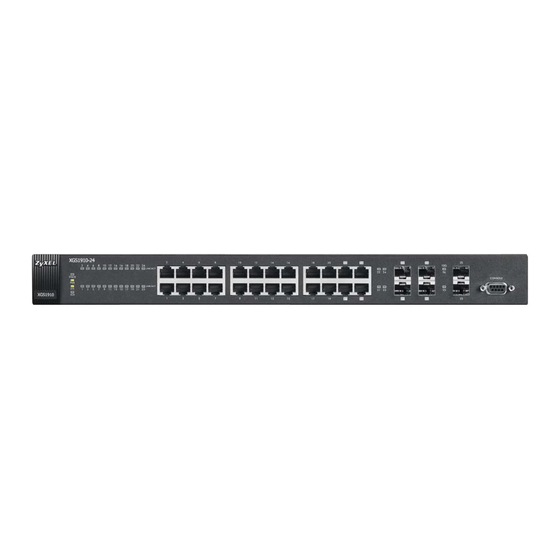
This chapter describes the front panel and rear panel of the Switch and shows you how to make the hardware connections. 3.1 Front Panel Connections The figure below shows the front panel of the Switch. Figure 8 Front Panel: GS1910-24 10/100/1000 Mbps RJ-45 / SFP Console Port 10/100/1000 Mbps... - Page 16 Chapter 3 Hardware Overview Figure 11 Front Panel: GS1910-48HP SFP Slots 10/100/1000 Mbps RJ-45 PoE Ports Figure 12 Front Panel: XGS1910-24 SFP+ Slot 10/100/1000 Mbps RJ-45 / SFP 10/100/1000 Mbps Dual Personality Interfaces Console Port RJ-45 Ethernet Ports Figure 13 Front Panel: XGS1910-48...
-
Page 17: Ethernet Ports
Form-Factor Pluggable (SFP) slot (also called a mini-GBIC (Gigabit Interfaces Interface Converter) slot), with one port active at a time. • 10/100/1000Base-T Ports or 10/100/1000Base-T PoE Ports (GS1910- 24HP and GS1910-48HP only): Connect these ports to high-bandwidth backbone network Ethernet switches using Category 5/5e/6 1000Base-T Ethernet cables. -
Page 18: Dual Personality Interfaces
• Connection speed: 1 Gigabit per second (Gbps) or 10 Gigabit per second (Gbps) To avoid possible eye injury, do not look into an operating fiber- optic module’s connectors. 3.1.3.1 Transceiver Installation Use the following steps to install a transceiver (SFP or SFP+ module). GS1910/XGS1910 Series User’s Guide... -
Page 19: Transceiver Removal
Figure 15 Installed Transceiver 3.1.3.2 Transceiver Removal Use the following steps to remove a transceiver (SFP or SFP+ module). Open the transceiver’s latch (latch styles vary). Figure 16 Opening the Transceiver’s Latch Example GS1910/XGS1910 Series User’s Guide... -
Page 20: Console Port
The following figure shows the rear panel of the Switch. The rear panel contains a connector for the power receptacle. The GS1910-48 and GS1910-48HP also have a console port on the rear panel. The XGS1910-48 has one console port and two SFP+ slots on the rear panel. -
Page 21: Power Connector
Chapter 3 Hardware Overview Figure 19 Rear Panel: GS1910-24HP Figure 20 Front Panel: GS1910-48 Figure 21 Front Panel: GS1910-48HP Figure 22 Front Panel: XGS1910-24 Figure 23 Front Panel: XGS1910-48 3.2.1 Power Connector Make sure you are using the correct power source as shown on the panel and that no objects obstruct the airflow of the fans. -
Page 22: Leds
Power supplied to all PoE Ethernet ports meets the IEEE (GS1910- 802.3at standard. 24HP and Amber Power supplied to all PoE Ethernet ports meets the IEEE GS1910- 802.3af standard. 48HP There is no power supplied. only) SFP Slots GS1910/XGS1910 Series User’s Guide... - Page 23 The link to a 100 Mbps Ethernet network is up. The link to an Ethernet network is down. 10G SFP+ Slots LNK/ACT Blue The port has a successful connection. Blinking The port is receiving or transmitting data. This link is disconnected. GS1910/XGS1910 Series User’s Guide...
- Page 24 Chapter 3 Hardware Overview GS1910/XGS1910 Series User’s Guide...
-
Page 25: The Web Configurator
• Java permissions (enabled by default). 4.2 System Login Start your web browser. Type “http://” and the IP address of the Switch (for example, the default management IP address is 192.168.1.1) in the Location or Address field. Press [ENTER]. GS1910/XGS1910 Series User’s Guide... -
Page 26: The Web Configurator Layout
4.3 The Web Configurator Layout The Port State Overview screen is the first screen that displays when you access the web configurator. The following figure shows the navigating components of a web configurator screen. Figure 25 The Web Configurator Layout GS1910/XGS1910 Series User’s Guide... - Page 27 This link takes you to screens where you can setup a system log server. Power Reduction This link takes you to a screen where you can enable EEE (Energy Efficient Ethernet) standard on a port to help reduce power consumption. GS1910/XGS1910 Series User’s Guide...
- Page 28 This link takes you to a screen where you can configure and view 802.1Q VLAN Membership parameters for the Switch. Ports This link takes you to a screen where you can configure the static VLAN (IEEE 802.1Q) settings on a port. Private VLANs GS1910/XGS1910 Series User’s Guide...
- Page 29 This link takes you to a screen to enable stacking and manage other members in the stack. sFlow This link takes you to a screen where you can configure an sFlow receiver (collector) and sFlow data sampling settings on the Switch. Monitor GS1910/XGS1910 Series User’s Guide...
- Page 30 This link takes you to a screen where you can view MVR SFM (Source-Filtered Multicast) Information information. IPMC IGMP This link takes you to a screen where you can view IGMP snooping status, IGMP group Snooping information and SFM (Source-Filtered Multicast) information. GS1910/XGS1910 Series User’s Guide...
- Page 31 This link takes you to a screen where you can back up your current Switch configuration to a computer. Upload This link takes you to a screen where you can restore a previously saved configuration from your computer to the Switch. GS1910/XGS1910 Series User’s Guide...
-
Page 32: Change Your Password
This is recommended after you finish a management session for security reasons. 4.6 Help The web configurator’s online help has descriptions of individual screens and some supplementary information. Click the Help link from a web configurator screen to view an online help description of that screen. GS1910/XGS1910 Series User’s Guide... -
Page 33: Chapter 5 Tutorials
Switch obtain a dynamic IP address from a DHCP server in your network. The following figure shows an example. Figure 27 Initial Setup Example: Management IP Address GS1910/XGS1910 Series User’s Guide... -
Page 34: How To Configure Login Accounts And Privilege Levels
You cannot change the user name and privilege level of the admin account. You can create new login accounts the user used to log in to the Switch and manage the privilege levels for login accounts. GS1910/XGS1910 Series User’s Guide... - Page 35 Click Configuration > Security > Switch > Users in the navigation panel. Click Add New User to create a new login account. Specify the user name, password and privilege level of the login account. Click Save to apply your changes. GS1910/XGS1910 Series User’s Guide...
-
Page 36: How To Manage A Configuration File
Backing up your Switch configurations allows you to create various “snap shots” of your device from which you may restore at a later date. To backup your configuration file, Click Maintenance > Configuration > Save and click Save Configuration. Click Save to display the File Download screen. GS1910/XGS1910 Series User’s Guide... -
Page 37: Restoring A Configuration File
5.3.2 Restoring a Configuration File If you want to upload a previously saved configuration file from your computer to the Switch, go to Maintenance > Configuration > Upload. Select the *.xml file from its path and click Upload. GS1910/XGS1910 Series User’s Guide... -
Page 38: How To Create A Vlan
By default, all ports on the Switch are in VLAN 1. In this example, you want to configure port 1 as a member of VLAN 2. Figure 28 VLAN Example GS1910/XGS1910 Series User’s Guide... -
Page 39: Setting Port Vid
Click Save to save the settings to the Switch. 5.4.1 Setting Port VID Use PVID to add a tag to incoming untagged frames received on that port so that the frames are forwarded to the VLAN group that the tag defines. GS1910/XGS1910 Series User’s Guide... - Page 40 TX Tag field at Untag_pvid to have the Switch remove a frame’s VLAN tag when the frame’s VLAN ID is the same as the PVID of the port on which the frame is transmitted. click Save to save your changes back to the Switch GS1910/XGS1910 Series User’s Guide...
-
Page 41: How To Set Up A Guest Vlan With Ieee 802.1X Authentication
VLAN to create VLAN2. Enter 200 in the VLAN ID field and enter a descriptive name (VLAN200 for example) in the VLAN Name field for this VLAN. Configure port 10 to be a permanent member of the VLAN. GS1910/XGS1910 Series User’s Guide... -
Page 42: Enabling Ieee 802.1X Port Authentication And Guest Vlan
Follow the steps below to enable port authentication to validate access to ports 1~8 to clients based on a RADIUS server. Click Configuration > Security > Network > NAS. Select Enabled in the Mode field to activate IEEE 802.1x authentication on the Switch. GS1910/XGS1910 Series User’s Guide... - Page 43 Click Save. Clients that attach to port 1, 2 or 3 and fail to authenticate with the RADIUS server now should be in VLAN 200 and can access the Internet via the Internet access gateway connected to port 10 which is also in VLAN 200, but cannot communicate with devices in VLAN 1. GS1910/XGS1910 Series User’s Guide...
-
Page 44: How To Use Private Vlan To Do Port Isolation In A Vlan
Go to Configuration > Private VLANs > PVLAN Membership. Click Add New Private VLAN. Enter a private VLAN ID (25 for example) in the PVLAN ID field. Select ports 2, 3, 4 and 25 to be members of this private VLAN. GS1910/XGS1910 Series User’s Guide... -
Page 45: Enabling Port Isolation
(static bindings). Use DHCP snooping to filter unauthorized DHCP packets on the network and to build the binding table dynamically. This can prevent clients from getting IP addresses from unauthorized DHCP servers. GS1910/XGS1910 Series User’s Guide... - Page 46 Access the Switch through http://192.168.1.1. Log into the Switch by entering the username (default: admin) and password (default: 1234). Section 5.4 on page 38 for how to create a VLAN and configure ports to join the VLAN. GS1910/XGS1910 Series User’s Guide...
- Page 47 Connect your DHCP server to port 5 and a computer (as DHCP client) to either port 6 or 7. The computer should be able to get an IP address from the DHCP server. If you put the DHCP server on port 6 or 7, the computer will not able to get an IP address. GS1910/XGS1910 Series User’s Guide...
-
Page 48: How To Use Dhcp Relay On The Switch
DHCP requests. In this example, you have configured your DHCP server (192.168.2.3) and want to have it assign a specific IP address (say 172.16.1.18) and gateway information to DHCP client A based on the slot GS1910/XGS1910 Series User’s Guide... -
Page 49: Creating A Vlan
Select Replace in the Relay Information Policy field to have the Switch remove the original DHCP relay agent information (if any) and add new information in the DHCP requests. Click Save to save your changes back to the Switch. GS1910/XGS1910 Series User’s Guide... -
Page 50: Troubleshooting
Make your physical connections - make sure that the ports that you want to belong to the trunk group are connected to the same destination. The following figure shows ports 2-5 on switch A connected to switch B. GS1910/XGS1910 Series User’s Guide... -
Page 51: Dynamic Port Trunking
• You must connect all ports point-to-point to the same Ethernet Switch and configure the ports for LACP trunking. • LACP only works on full-duplex links. • All ports in the same trunk group must have the same media type, speed, duplex mode and flow control settings. To configure the settings: GS1910/XGS1910 Series User’s Guide... -
Page 52: How To Analyze Traffic Using Mirroring
VLAN and sent to a destination port in a remote switch through the intermediate ports that connect to other switches. Reflector port Destination port Intermediate port Intermediate port Intermediate port Source port Intermediate port Remote Port Mirroring VLAN GS1910/XGS1910 Series User’s Guide... -
Page 53: Configuring Mirroring
Select the direction of traffic flow you want to copy (Both in this example) on port 7. Click Save. You then should be able to receive a copy of the traffic passing through port 7 to examine it in more detail without interfering with the traffic flow on the original port. GS1910/XGS1910 Series User’s Guide... -
Page 54: Configuring Remote Port Mirroring
Select the direction of traffic flow you want to copy (Both in this example) on the source port (port 4 in this example). Configure port 12 to act as an intermediate port to which traffic from the source port is copied that connects to Switch B. GS1910/XGS1910 Series User’s Guide... - Page 55 Chapter 5 Tutorials Click Save. GS1910/XGS1910 Series User’s Guide...
- Page 56 Chapter 5 Tutorials Click Configuration > Spanning Tree > CIST Ports to disable (R)STP on the reflector port to prevent the port from entering blocking state. GS1910/XGS1910 Series User’s Guide...
- Page 57 VLAN and configure the intermediate ports as a member of this VLAN. Configure ports (3 and 4 for example) to act as the intermediate ports that connect to Switch A and Switch C. GS1910/XGS1910 Series User’s Guide...
- Page 58 Go to Configuration > MAC Table to disable MAC address learning on the intermediate ports so that the Switch will NOT filter or forward a frame based on the frame’s destination MAC address, or even drop the frame whose MAC address is not in the MAC address table on these ports. GS1910/XGS1910 Series User’s Guide...
- Page 59 Configure a port (2 for example) to act as the intermediate port that connects to Switch B. Configure a port (10 for example) to act as the destination port that receives the copy of traffic from the source port on Switch A for analysis. Click Save. GS1910/XGS1910 Series User’s Guide...
-
Page 60: How To Use Igmp Snooping To Reduce Multicast Traffic Passing Through Your Switch
Switch. The Switch can perform IGMP snooping on up to 32 VLANs. You can configure the Switch to automatically learn multicast group membership of any VLANs. GS1910/XGS1910 Series User’s Guide... - Page 61 In fast leave mode, the Switch removes an IGMP snooping membership entry immediately from the forwarding table when an IGMP leave message is received on the port from a host. This helps speed up the leave process. Also set the maximum number of multicast groups the ports can join. GS1910/XGS1910 Series User’s Guide...
- Page 62 IGMP General Query (GQ) and Group-Specific Query (GSQ) messages to this VLAN. A querier sends out an IGMP Group-Specific Query (GSQ) message to determine whether the hosts connected to the port should remain in the specific multicast group. GS1910/XGS1910 Series User’s Guide...
-
Page 63: How To Configure Access Control List (Acl) For Packets Filtering
In this example, you configure an ACL rule to identify all traffic coming from host A connected to port 9 and restrict the host’s access to a specific IPv4 network. Port 9 10.1.2.0/24 Access the Switch through http://192.168.1.1. Log into the Switch by entering the username (default: admin) and password (default: 1234). GS1910/XGS1910 Series User’s Guide... - Page 64 Select IPv4 in the Frame Type field. Select Network in the DIP Filter field and specify the destination address and subnet mask of matched traffic in this policy. Set Action to Deny to block all mattached traffic. GS1910/XGS1910 Series User’s Guide...
- Page 65 Go to Configuration > Security > Network > ACL > Ports. Enter the ID of the ACL policy you just created in the Policy ID field of the port to which you want to apply this policy, that is, port 9 to which host A is connected in this example. GS1910/XGS1910 Series User’s Guide...
-
Page 66: How To Reset The Switch Via The Console Port
When you see the message “Executing boot script in 3.000 seconds - enter ^C to abort” press the Ctrl-c key combination to stop the automatic boot and then type default. Type reset after the “Erase from 0x40080000-0x4017ffff: ....” message. GS1910/XGS1910 Series User’s Guide... - Page 67 DDR SDRAM: Testing [0x800214d8-0x87fe1000] - Write Sweep ..........................Done DDR SDRAM: Testing [0x800214d8-0x87fe1000] - Read Sweep ..........................Done 3 tests completed successfully. RedBoot> fis load -d managed Image loaded from 0x80040000-0x806a4d20 RedBoot> go Username: GS1910/XGS1910 Series User’s Guide...
- Page 68 Chapter 5 Tutorials GS1910/XGS1910 Series User’s Guide...
-
Page 69: Chapter 6 Troubleshooting
Turn the Switch off and on (in DC models or if the DC power supply is connected in AC/DC models). Disconnect and re-connect the power adaptor or cord to the Switch (in AC models or if the AC power supply is connected in AC/DC models). If the problem continues, contact the vendor. GS1910/XGS1910 Series User’s Guide... -
Page 70: Switch Access And Login
I cannot see or access the Login screen in the web configurator. Make sure you are using the correct IP address. • The default management IP address is 192.168.1.1. • If you changed the IP address, use the new IP address. GS1910/XGS1910 Series User’s Guide... - Page 71 Configuration > Security > Switch > Access Management screen for HTTP/HTTPS and SNMP. Computers not belonging to the secured client set cannot get permission to access the Switch. GS1910/XGS1910 Series User’s Guide...
- Page 72 Chapter 6 Troubleshooting GS1910/XGS1910 Series User’s Guide...
-
Page 73: Appendix A Legal Information
The contents of this publication may not be reproduced in any part or as a whole, transcribed, stored in a retrieval system, translated into any language, or transmitted in any form or by any means, electronic, mechanical, magnetic, optical, chemical, photocopying, manual, or otherwise, without the prior written permission of ZyXEL Communications Corporation. Published by ZyXEL Communications Corporation. All rights reserved. - Page 74 Your product is marked with this symbol, which is known as the WEEE mark. WEEE stands for Waste Electronics and Electrical Equipment. It means that used electrical and electronic products should not be mixed with general waste. Used electrical and electronic equipment should be treated separately. GS1910/XGS1910 Series User’s Guide...
-
Page 75: Index
Installation Rack-mounting installation DHCP snooping freestanding trusted ports precautions untrusted ports Internet Protocol version 6, see IPv6 disclaimer introduction documentation IP source guard related DHCP snooping IPv6 Neighbor Discovery Protocol ping GS1910/XGS1910 Series User’s Guide... - Page 76 DHCP snooping other documentation ventilation holes password power wires VLAN product registration PVID PVID (Priority Frame) warranty note registration web configurator 8, 25 product getting help layout related documentation login rubber feet logout navigation panel GS1910/XGS1910 Series User’s Guide...
Need help?
Do you have a question about the GS1910 and is the answer not in the manual?
Questions and answers