Table of Contents
Advertisement
Advertisement
Table of Contents
Troubleshooting

Related Manuals for ZyXEL Communications GS1910 series


Summary of Contents for ZyXEL Communications GS1910 series
- Page 1 GS1910/XGS1910 Series GbE Smart Managed Switch Version 1.00 Edition 2, 11/2014 Quick Start Guide User’s Guide Default Login Details IP Address http://192.168.1.1 User Name admin www.zyxel.com Password 1234 Copyright © 2014 ZyXEL Communications Corporation...
- Page 2 IMPORTANT! READ CAREFULLY BEFORE USE. KEEP THIS GUIDE FOR FUTURE REFERENCE. Note: This guide is a reference for a series of products. Therefore some features or options in this guide may not be available in your product. Screenshots and graphics in this book may differ slightly from your product due to differences in your product firmware or your computer operating system.
-
Page 3: Table Of Contents
Table of Contents Table of Contents Table of Contents ..........................3 Chapter 1 Getting to Know Your Switch.......................5 1.1 Introduction ............................5 1.1.1 Bridging Example ........................5 1.1.2 High Performance Switching Example ..................6 1.1.3 Gigabit Ethernet to the Desktop ....................6 1.1.4 IEEE 802.1Q VLAN Application Example ..................7 1.1.5 IPv6 Support ..........................8 1.2 Ways to Manage the Switch ........................8 1.3 Good Habits for Managing the Switch ....................8... - Page 4 Table of Contents 4.5 Logging Out of the Web Configurator ....................28 4.6 Help ..............................28 Chapter 5 Tutorials ...............................29 5.1 How to Change Switch Management IP Address ................29 5.2 How to Configure Login Accounts and Privilege Levels ..............30 5.3 How to Manage a Configuration File ....................32 5.3.1 Backing up a Configuration File ....................32 5.3.2 Restoring a Configuration File ....................33 5.4 How to Create a VLAN ........................34...
-
Page 5: Getting To Know Your Switch
H A PT ER Getting to Know Your Switch This chapter introduces the main features and applications of the Switch. 1.1 Introduction Your Switch is a Gigabit Ethernet (GbE) switch with 20, 44 or 48 10/100/1000 Mbps Ethernet ports. The GS1910-24, GS1910-24HP, XGS1910-24 or XGS1910-48 also has four GbE dual personality interfaces. -
Page 6: High Performance Switching Example
Chapter 1 Getting to Know Your Switch Figure 1 Bridging Application Backbone Sales 1.1.2 High Performance Switching Example The Switch is ideal for connecting two geographically dispersed networks that need high bandwidth. In the following example, a company uses the optional 10 Gigabit uplink modules to connect the headquarters to a branch office network. -
Page 7: Ieee 802.1Q Vlan Application Example
Chapter 1 Getting to Know Your Switch access to a data server and the Internet. The uplink module supports a fiber-optic connection which alleviates the distance limitations of copper cabling. In this example, all computers can share high-speed applications on the server and access the Internet. -
Page 8: Ipv6 Support
Chapter 1 Getting to Know Your Switch Figure 4 Shared Server Using VLAN Example 1.1.5 IPv6 Support IPv6 (Internet Protocol version 6), is designed to enhance IP address size and features. The increase in IPv6 address size to 128 bits (from the 32-bit IPv4 address) allows up to 3.4 x 10 addresses. - Page 9 Chapter 1 Getting to Know Your Switch • Back up the configuration (and make sure you know how to restore it). Restoring an earlier working configuration may be useful if the device becomes unstable or even crashes. If you forget your password, you will have to reset the Switch to its factory default settings. If you backed up an earlier configuration file, you would not have to totally re-configure the Switch.
-
Page 10: Hardware Installation And Connection
H A PT ER Hardware Installation and Connection This chapter shows you how to install and connect the Switch. 2.1 Freestanding Installation Make sure the Switch is clean and dry. Set the Switch on a smooth, level surface strong enough to support the weight of the Switch and the connected cables. -
Page 11: Mounting The Switch On A Rack
Chapter 2 Hardware Installation and Connection 2.2 Mounting the Switch on a Rack This section lists the rack mounting requirements and precautions and describes the installation steps. 2.2.1 Rack-mounted Installation Requirements • Two mounting brackets. • Eight M3 flat head screws and a #2 Philips screwdriver. •... - Page 12 Chapter 2 Hardware Installation and Connection Figure 7 Mounting the Switch on a Rack Using a #2 Philips screwdriver, install the M5 flat head screws through the mounting bracket holes into the rack. Repeat steps to attach the second mounting bracket on the other side of the rack. GS1910/XGS1910 Series User’s Guide...
-
Page 13: Chapter 3 Hardware Overview
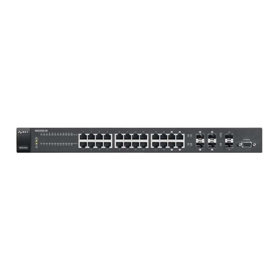
H A PT ER Hardware Overview This chapter describes the front panel and rear panel of the Switch and shows you how to make the hardware connections. 3.1 Front Panel Connections The figure below shows the front panel of the Switch. Figure 8 Front Panel: GS1910-24 10/100/1000 Mbps RJ-45 / SFP Console Port... - Page 14 Chapter 3 Hardware Overview Figure 11 Front Panel: GS1910-48HP SFP Slots 10/100/1000 Mbps RJ- 45 PoE Ports Figure 12 Front Panel: XGS1910-24 SFP+ Slot 10/100/1000 Mbps RJ-45 / SFP 10/100/1000 Mbps RJ- Dual Personality Interfaces Console Port 45 Ethernet Ports Figure 13 Front Panel: XGS1910-48 SFP+ Slot 10/100/1000 Mbps RJ-...
-
Page 15: Ethernet Ports
Chapter 3 Hardware Overview Table 1 Panel Connections (continued) CONNECTOR DESCRIPTION Dual Personality Each interface has one 10/100/1000Base-T RJ-45 port and one Small Form- Interfaces Factor Pluggable (SFP) slot (also called a mini-GBIC (Gigabit Interface Converter) slot), with one port active at a time. •... -
Page 16: Sfp/Sfp+ Slots
Chapter 3 Hardware Overview Note: Connect the 1000Base-T RJ-45 port only after the transceiver is removed from the corresponding SFP slot. 3.1.3 SFP/SFP+ Slots These are slots for Small Form-Factor Pluggable (SFP) or SFP+ transceivers. The SFP is also referred to as a mini-GBIC. The SFP+ (SFP Plus) is an enhanced version of the SFP and supports data rates of 10 Gbps. -
Page 17: Console Port
Chapter 3 Hardware Overview 3.1.3.2 Transceiver Removal Use the following steps to remove a transceiver (SFP or SFP+ module). Open the transceiver’s latch (latch styles vary). Figure 16 Opening the Transceiver’s Latch Example Pull the transceiver out of the slot. Figure 17 Transceiver Removal Example 3.1.4 Console Port For local management, you can use a computer with terminal emulation software configured to the... -
Page 18: Power Connector
Chapter 3 Hardware Overview Figure 18 Rear Panel: GS1910-24 Figure 19 Rear Panel: GS1910-24HP Figure 20 Front Panel: GS1910-48 Figure 21 Front Panel: GS1910-48HP Figure 22 Front Panel: XGS1910-24 Figure 23 Front Panel: XGS1910-48 3.2.1 Power Connector Make sure you are using the correct power source as shown on the panel and that no objects obstruct the airflow of the fans. -
Page 19: Leds
Chapter 3 Hardware Overview Note: Use only power wires of the required diameter for connecting the Switch to a power supply. 3.3 LEDs The following table describes the LEDs. Table 2 LEDs COLOR STATUS DESCRIPTION Green Each Ethernet port’s LED is changed to act as a PoE LED by (GS1910- using the LED MODE button on the front panel. - Page 20 Chapter 3 Hardware Overview Table 2 LEDs (continued) COLOR STATUS DESCRIPTION LNK/ACT Green Blinking The system is transmitting/receiving to/from a 1000 Mbps Ethernet network. The link to a 1000 Mbps Ethernet network is up. Amber Blinking The system is transmitting/receiving to/from a 100 Mbps Ethernet network.
-
Page 21: The Web Configurator
H A PT ER The Web Configurator This section introduces the configuration and functions of the web configurator. 4.1 Introduction The web configurator is an HTML-based management interface that allows easy Switch setup and management via Internet browser. Use Internet Explorer 7.0 and later or Firefox 10.0 and later versions. -
Page 22: The Web Configurator Layout
Chapter 4 The Web Configurator Figure 24 Web Configurator: Login Click OK to view the first web configurator screen. 4.3 The Web Configurator Layout The Port State Overview screen is the first screen that displays when you access the web configurator. - Page 23 Chapter 4 The Web Configurator A - Click the menu items to open submenu links, and then click on a submenu link to open the screen in the main window. B, C - These are quick links which allow you to perform certain tasks no matter which screen you are currently working in.
- Page 24 Chapter 4 The Web Configurator Table 4 Navigation Panel Links (continued) LINK DESCRIPTION Ports This link takes you to a screen where you can configure speed, flow control, the maximum frame size and power control settings for individual Switch ports. Security Switch This link takes you to screens where you can change the system login password, manage...
- Page 25 Chapter 4 The Web Configurator Table 4 Navigation Panel Links (continued) LINK DESCRIPTION PVLAN This link takes you to a screen where you can create private VLANs on the Switch. Membership This screen is not available on the XGS1910-24 or XGS1910-48. Port Isolation This link takes you to a screen where you can enable port isolation on ports in a private VLAN or IEEE 802.1Q tagged VLAN to prevent communication between ports in the same...
- Page 26 Chapter 4 The Web Configurator Table 4 Navigation Panel Links (continued) LINK DESCRIPTION System Information This link takes you to a screen that displays general system information. CPU Load This link takes you to a screen that displays what percentage of the Switch’s processing ability is currently used.
- Page 27 Chapter 4 The Web Configurator Table 4 Navigation Panel Links (continued) LINK DESCRIPTION MLD Snooping This link takes you to a screen where you can view MLD snooping status, MLD group information and SFM (Source-Filtered Multicast) information.. LLDP Neighbours This link takes you to a screen where you can view the LLDP neighboring device information.
-
Page 28: Change Your Password
Chapter 4 The Web Configurator 4.3.1 Change Your Password After you log in for the first time, it is recommended you change the default administrator password. Click Configuration > Security > Switch > Users to display the next screen. Figure 26 Change Administrator Login Password 4.4 Switch Lockout You could block yourself (and all others) from using in-band-management (managing through the data ports) if you do one of the following:... -
Page 29: Chapter 5 Tutorials
H A PT ER Tutorials This chapter provides some examples of using the Web Configurator to set up and use the Switch. The tutorials include: • How to Change Switch Management IP Address • How to Configure Login Accounts and Privilege Levels •... -
Page 30: How To Configure Login Accounts And Privilege Levels
Chapter 5 Tutorials Connect your computer to the Switch’s port which is in VLAN1 (the default management VLAN). Open your web browser and enter 192.168.1.1 (the default management IP address) in the address bar to access the web configurator. See Section 4.2 on page 21 for more information. - Page 31 Chapter 5 Tutorials In this example, you create a login account with the following information. USER NAME PASSWORD PRIVILEGE LEVEL user1 qwert12345 Log into the Switch’s Web Configurator with the admin account. Click Configuration > Security > Switch > Users in the navigation panel. Click Add New User to create a new login account.
-
Page 32: How To Manage A Configuration File
Chapter 5 Tutorials 5.3 How to Manage a Configuration File Configuration files define the Switch’s settings. You can use the Configuration screens to back up configuration files from the Switch to your computer and restore them from your computer to the Switch. -
Page 33: Restoring A Configuration File
Chapter 5 Tutorials Choose a location to save the file on your computer from the Save in drop-down list box and type a descriptive name for it in the File name list box. Click Save to save the configuration file to your computer. 5.3.2 Restoring a Configuration File If you want to upload a previously saved configuration file from your computer to the Switch, go to Maintenance >... -
Page 34: How To Create A Vlan
Chapter 5 Tutorials After the upload is successful, the following screen displays. "config" is the name of the configuration file on the Switch, so your backup configuration file is automatically renamed when you restore using this screen. 5.4 How to Create a VLAN VLANs confine broadcast frames to the VLAN group in which the port(s) belongs. -
Page 35: Setting Port Vid
Chapter 5 Tutorials Access the Switch through http://192.168.1.1. Log into the Switch with the admin account. Click Configuration > VLANs > VLAN Membership in the navigation panel. Click Add New VLAN to create VLAN2. Enter 2 in the VLAN ID field and enter a descriptive name in the VLAN Name field for the VLAN2 network. -
Page 36: How To Set Up A Guest Vlan With Ieee 802.1X Authentication
Chapter 5 Tutorials Figure 29 Port VID Example Click Configuration > VLANs > Ports in the navigation panel. Set Port VLAN Mode to Specific and enter 2 in the Port VLAN ID field for port 1. To ensure that VLAN-unaware devices (such as computers and hubs) can receive frames properly, you can either select Untag_all in the TX Tag field to set the Switch to remove any VLAN tags before sending or leave the TX Tag field at Untag_pvid to have the Switch remove a frame’s VLAN tag when the frame’s VLAN ID is the same as the PVID of the port on which the frame is... -
Page 37: Creating A Vlan For Port Which Is Not Ieee 802.1X Enabled
Chapter 5 Tutorials in order to access the ports. You want to assign clients that connect to ports 1, 2 or 3 to a guest VLAN (200 for example) when they fail to authenticate with the authentication server. In this guest VLAN, clients can surf the Internet through a gateway attached to port 10, but are not allowed to access other network resources, such as the mail server or local data base. -
Page 38: Enabling Ieee 802.1X Port Authentication And Guest Vlan
Chapter 5 Tutorials Click Configuration > VLANs > Ports in the navigation panel. Set Port VLAN Mode to Specific and enter 200 in the Port VLAN ID field for port 10 to add a tag to incoming untagged frames received on these ports so that the frames are forwarded to the VLAN group that the tag defines. - Page 39 Chapter 5 Tutorials Select the Reauthentication Enabled check box to have a subscriber periodically re-enter his or her username and password to stay connected to the port. Select the Guest VLAN Enabled check box and enter the guest VLAN ID (200 in this example) to enable the guest VLAN on the Switch.
-
Page 40: How To Use Private Vlan To Do Port Isolation In A Vlan
Chapter 5 Tutorials 5.6 How to Use Private VLAN to Do Port Isolation in a VLAN This tutorial is not applicable to the XGS1910-24 or XGS1910-48. Port isolation prevents communication between ports. You want to do port isolation in a VLAN but still allow ports to access the Internet or network resources through the uplink port in the same VLAN. -
Page 41: Enabling Port Isolation
Chapter 5 Tutorials Click Save to save the settings to the Switch. 5.6.2 Enabling Port Isolation Follow the steps below to configure port isolation. Click Configuration > Private VLANs > Port Isolation. Select the check boxes of ports 2, 3 and 4, and click Save to add them to the isolated port list so that they cannot send traffic to each other. - Page 42 Chapter 5 Tutorials If you want to use dynamic bindings to filter unauthorized ARP packets (typical implementation), you have to enable DHCP snooping before you enable ARP inspection. Trusted vs. Untrusted Ports Every port is either a trusted port or an untrusted port for DHCP snooping. Trusted ports are connected to DHCP servers or other switches.
- Page 43 Chapter 5 Tutorials Go to Configuration > Security > Network > DHCP > Snooping to activate DHCP snooping on the Switch. Specify whether ports are trusted or untrusted ports for DHCP snooping. Select Trusted in the Mode field for port 5 because the DHCP server is connected to port 5. Set ports 6 and 7 to Untrusted as they are connected to DHCP clients.
-
Page 44: How To Use Dhcp Relay On The Switch
Chapter 5 Tutorials Go to Monitor > Security > Network > IP Source Guard to look at the current dynamic bindings for DHCP snooping. You should see an IP binding for port 6 or 7 in VLAN 100. 5.8 How to Use DHCP Relay on the Switch If the DHCP clients and the DHCP server are not in the same broadcast domain, the Switch can help to relay network information (such as the IP address and subnet mask) between a DHCP client and a DHCP server. -
Page 45: Creating A Vlan
Chapter 5 Tutorials DHCP Server 192.168.2.3 Port 2 PVID=102 VLAN 102 172.16.1.18 5.8.1 Creating a VLAN Access the web configurator through the Switch’s port which is in VLAN 1. Configure port 2 as a member of VLAN 102. See Section 5.4 on page 34 for how to create a VLAN and configure ports to join the VLAN. -
Page 46: Troubleshooting
Chapter 5 Tutorials 5.8.3 Troubleshooting Check the client A’s IP address. If it did not receive the IP address 172.16.1.18, make sure: Client A is connected to the Switch’s port 2 in VLAN 102. 5.9 How to Use Link Aggregation to Group Multiple Ports into One Logical Link Link aggregation (trunking) is the grouping of physical ports into one logical higher-capacity link. -
Page 47: Dynamic Port Trunking
Chapter 5 Tutorials Configure static trunking - Click Configuration > Aggregation > Static. In this screen select the traffic distribution type(s) used by this group and select the ports that should belong to this group as shown in the figure below. Packets from the same source and/or to the same destination are sent over the same link within the trunk. -
Page 48: How To Analyze Traffic Using Mirroring
Chapter 5 Tutorials Click Configuration > Aggregation > LACP. Enable LACP on ports for which you want to create a trunk group using LACP. Leave the other fields to their default settings. Click Save. 5.10 How to Analyze Traffic Using Mirroring With mirroring, you can copy a traffic flow (passing through the source port(s)) to another port (a destination port you copy the traffic to) in order that you can examine the traffic from the destination port without interference. - Page 49 Chapter 5 Tutorials Access the Switch through http://192.168.1.1. Log into the Switch by entering the username (default: admin) and password (default: 1234). Go to Configuration > Port Mirroring. Select Enabled in the Mode field to activate mirroring on the Switch. Set Type to Mirror to do mirroring in one standalone switch.
-
Page 50: Configuring Remote Port Mirroring
Chapter 5 Tutorials 5.10.2 Configuring Remote Port Mirroring In this example, there are three switches (A, B and C) in your network. You are connected to port 10 of switch C but want to monitor traffic received or transmitted on port 4 of switch A. The copied traffic is forwarded to remote port mirroring VLAN 100. - Page 51 Chapter 5 Tutorials Click Configuration > Spanning Tree > CIST Ports to disable (R)STP on the reflector port to prevent the port from entering blocking state. GS1910/XGS1910 Series User’s Guide...
- Page 52 Chapter 5 Tutorials Go to Configuration > MAC Table to disable MAC address learning on the reflector and intermediate ports so that the Switch will NOT filter or forward a frame based on the frame’s destination MAC address, or even drop the frame whose MAC address is not in the MAC address table on these ports.
- Page 53 Chapter 5 Tutorials In Switch B: Access the Switch through http://192.168.1.1. Log into the Switch by entering the username (default: admin) and password (default: 1234). Go to Configuration > Port Mirroring. Select Enabled in the Mode field to activate mirroring on the Switch.
- Page 54 Chapter 5 Tutorials In Switch C: Access the Switch through http://192.168.1.1. Log into the Switch by entering the username (default: admin) and password (default: 1234). Go to Configuration > Port Mirroring. Select Enabled in the Mode field to activate mirroring on the Switch.
- Page 55 Chapter 5 Tutorials Go to Configuration > MAC Table to disable MAC address learning on the intermediate and destination ports so that the Switch will NOT filter or forward a frame based on the frame’s destination MAC address, or even drop the frame whose MAC address is not in the MAC address table on these ports.
-
Page 56: How To Use Igmp Snooping To Reduce Multicast Traffic Passing Through Your Switch
Chapter 5 Tutorials 5.11 How to Use IGMP Snooping to Reduce Multicast Traffic Passing through your Switch The Switch can passively snoop on IGMP packets transferred between IP multicast routers/switches and IP multicast hosts to learn the IP multicast group membership. It checks IGMP packets passing through it, picks out the group registration information, and configures multicasting accordingly. - Page 57 Chapter 5 Tutorials Proxy Access the Switch through http://192.168.1.1. Log into the Switch by entering the username (default: admin) and password (default: 1234). Go to Configuration > IPMAC > IGMP Snooping > Basic Configuration. Select the Snooping Enabled check box to activate IGMP snooping on the Switch. The Unknown Multicast Flooding Enabled check box is selected by default and the Switch will send the frame(s) to all ports when the it receives an unknown multicast frame.
- Page 58 Chapter 5 Tutorials 10 Configure both the router port and the ports to which the multicast clients connect as a member of VLAN 1234. See Section 5.4 on page 34 for how to create a VLAN and configure ports to join the VLAN.
-
Page 59: How To Configure Access Control List (Acl) For Packets Filtering
Chapter 5 Tutorials 5.12 How to Configure Access Control List (ACL) for Packets Filtering Access Control List (ACL) can be used as a simple packet filtering firewall to filter incoming traffic and prevent certain traffic from entering your network. ACL groups traffic into data flows according to specific criteria such as the source address, destination address, source port number, destination port number or incoming port number, and also define actions to be performed for a classified traffic flow. - Page 60 Chapter 5 Tutorials Set Action to Deny to block all mattached traffic. Click Save. The ordering of your rules is very important as rules are applied in the order that they are listed. This tutorial uses the XGS1910-24 screens as an example. The screens may vary slightly for different models.
-
Page 61: How To Reset The Switch Via The Console Port
Chapter 5 Tutorials 10 Click Save. The ACL configurations in the Ports page (such as Action or Rate Limiter ID) apply only to traffic that does NOT matched the specified ACL policy. 5.13 How to Reset the Switch via the Console Port If you lock yourself (and others) from the Switch or forget the administrator password, you will need to reload the factory-default configuration file or reset the Switch back to the factory defaults. - Page 62 Chapter 5 Tutorials >+M25PXX : Init device with JEDEC ID 0xC22018. Jaguar-1 board detected (VSC7460 Rev. B). RedBoot(tm) bootstrap and debug environment [ROMRAM] Non-certified release, version 1_12_2-customized-z-XGS - built 19:04:36, Feb 8 2012 Copyright (C) 2000, 2001, 2002, 2003, 2004, 2005, 2006, 2007, 2008, 2009 Free Software Foundation, Inc.
-
Page 63: Chapter 6 Troubleshooting
H A PT ER Troubleshooting This chapter offers some suggestions to solve problems you might encounter. The potential problems are divided into the following categories. • Power, Hardware Connections, and LEDs • Switch Access and Login 6.1 Power, Hardware Connections, and LEDs The Switch does not turn on. -
Page 64: Switch Access And Login
Chapter 6 Troubleshooting One of the LEDs does not behave as expected. Make sure you understand the normal behavior of the LED. See Section 3.3 on page Check the hardware connections. See Section 3.1 on page Inspect your cables for damage. Contact the vendor to replace any damaged cables. Turn the Switch off and on (in DC models or if the DC power supply is connected in AC/DC models). - Page 65 Chapter 6 Troubleshooting • If you changed the IP address and have forgotten it, see the troubleshooting suggestions for forgot the IP address for the Switch. Check the hardware connections, and make sure the LEDs are behaving as expected. See Section 3.3 on page Make sure your Internet browser does not block pop-up windows and has JavaScripts and Java...
- Page 66 Chapter 6 Troubleshooting GS1910/XGS1910 Series User’s Guide...
-
Page 67: Appendix A Legal Information
The contents of this publication may not be reproduced in any part or as a whole, transcribed, stored in a retrieval system, translated into any language, or transmitted in any form or by any means, electronic, mechanical, magnetic, optical, chemical, photocopying, manual, or otherwise, without the prior written permission of ZyXEL Communications Corporation. Published by ZyXEL Communications Corporation. All rights reserved. -
Page 68: Safety Warnings
Appendix A Legal Information CE EMC statement This is Class A Product. In domestic environment this product may cause radio interference in which case the user may be required to take adequate measures. List of national codes COUNTRY ISO 3166 2 LETTER CODE COUNTRY ISO 3166 2 LETTER CODE Austria... - Page 69 Appendix A Legal Information Environment statement WEEE Directive Your product is marked with this symbol, which is known as the WEEE mark. WEEE stands for Waste Electronics and Electrical Equipment. It means that used electrical and electronic products should not be mixed with general waste. Used electrical and electronic equipment should be treated separately.
- Page 70 Appendix A Legal Information Environmental Product Declaration GS1910/XGS1910 Series User’s Guide...
-
Page 71: Zyxel Limited Warranty
Appendix A Legal Information 類 Viewing Certifications Go to http://www.zyxel.com to view this product’s documentation and certifications. ZyXEL Limited Warranty ZyXEL warrants to the original end user (purchaser) that this product is free from any defects in material or workmanship for a specific period (the Warranty Period) from the date of purchase. -
Page 72: Index
Index Index default settings applications bridging IEEE 802.1Q VLAN switched workgroup FCC interference statement front panel basic setup tutorial binding getting help binding table building hardware installation mounting certifications hardware overview viewing changing the password console port settings copyright Installation Rack-mounting installation freestanding... - Page 73 Index LEDs SNMP lockout status login password switch lockout managing the device tagged VLAN good habits trademarks using SNMP. See SNMP. transceiver using the web configurator. See web configurator. installation mini GBIC ports removal connection speed trusted ports connector type DHCP snooping transceiver installation tutorials...
Need help?
Do you have a question about the GS1910 series and is the answer not in the manual?
Questions and answers