Table of Contents
Advertisement
Quick Links
UM2514
User manual
Evaluation board with STM32G4xxQE MCU
Introduction
The STM32G474E-EVAL board is a complete demonstration and development platform for
®
®
the STMicroelectronics Arm
Cortex
-M4 core-based STM32G474QET6 microcontroller. It
features three FDCAN controllers, four I²C Fast mode plus, five USART/UARTs and one
LPUART, four SPIs, one SAI port, USB FS and IRTIM communication interfaces, UCPD,
five 12-bit ADCs, seven 12-bit DAC channels, seven comparators, six operational
amplifiers, 17 timers, 96 Kbytes of internal SRAM, 32 Kbytes of CCM SRAM, 512 Kbytes of
flash memory, and JTAG/SWD debugging support.
The STM32G474E-EVAL, shown in
Figure 1
and
Figure
2, is used as a reference design for
user application development before porting to the final product. The STM32G484E-EVAL is
populated with an STM32G484QET6 MCU with cryptography. The STM32G474E-EVAL1 is
configured as a dedicated motor control board.
The full range of hardware features available on the board helps users to optimize the
application development by the evaluation of all the peripherals (USB FS, UCPD, USART,
audio, ADC and DAC, differential ADC, TFT LCD, potentiometer/LDR, SRAM, Quad-SPI
flash memory device, microSD™ card, smartcard, FDCAN transceiver, high-brightness
LED, motor control connectors, temperature sensor, and others). Extension headers provide
an easy connection to a daughterboard for specific applications.
STLINK-V3E is integrated into the board, as the embedded in-circuit debugger and
programmer for the STM32 MCU and the USB Virtual COM port bridge.
The three products (STM32G474E-EVAL, STM32G484E-EVAL, and STM32G474E-EVAL1)
are described in this user manual, together with STM32G474E-EVAL figures.
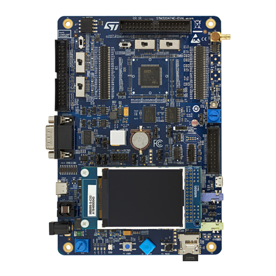
STM32G474E-EVAL top view
STM32G474E-EVAL bottom view
Figure 1.
Figure 2.
Pictures are not contractual.
January 2023
UM2514 Rev 5
1/66
www.st.com
1
Advertisement
Table of Contents

Subscribe to Our Youtube Channel
Related Manuals for ST STM32G474E-EVAL


Summary of Contents for ST STM32G474E-EVAL
-
Page 1: Figure 1. Stm32G474E-Eval Top View
UM2514 User manual Evaluation board with STM32G4xxQE MCU Introduction The STM32G474E-EVAL board is a complete demonstration and development platform for ® ® the STMicroelectronics Arm Cortex -M4 core-based STM32G474QET6 microcontroller. It features three FDCAN controllers, four I²C Fast mode plus, five USART/UARTs and one... -
Page 2: Table Of Contents
Contents UM2514 Contents Features ........... 8 Ordering information . - Page 3 UM2514 Contents 5.11.1 Board modifications to enable motor control ..... 31 5.11.2 Limitations ..........31 5.12 FDCAN .
- Page 4 CN31 smartcard connector ........54 STM32G474E-EVAL I/O assignment ......55...
- Page 5 UM2514 Contents STM32G474E-EVAL, STM32G474E-EVAL1, and STM32G484E-EVAL board information ......60 Product marking ..........60 STM32G474E-EVAL, STM32G474E-EVAL1, and STM32G484E-EVAL product history .
- Page 6 STM32G474E-EVAL I/O assignment ........
- Page 7 Hardware block diagram ........... 12 Figure 4. STM32G474E-EVAL Evaluation board layout (top view) ......13 Figure 5.
-
Page 8: Features
Features UM2514 Features • STM32G474QET6 (STM32G474E-EVAL and STM32G474E-EVAL1) or ® ® STM32G484QET6 (STM32G484E-EVAL) Arm Cortex -M4 core-based microcontroller with 512 Kbytes of flash memory and 96 Kbytes of RAM in an LQFP128 package • 240x320 TFT color LCD module with SPI interface •... - Page 9 UM2514 Features • Flexible power-supply options: ST-LINK USB V , USB connector, or external sources • Microcontroller supply voltage: fixed 3.3 V or adjustable range from 1.62 to 3.6 V • On-board STLINK-V3E debugger/programmer with USB reenumeration capability: mass storage, Virtual COM port, and debug port •...
-
Page 10: Ordering Information
Ordering information UM2514 Ordering information To order the STM32G474E-EVAL, STM32G474E-EVAL1, or STM32G484E-EVAL Evaluation board, refer to Table 1. Additional information is available in the datasheet and reference manual of the targeted STM32. Table 1. List of available products Order code... -
Page 11: Development Environment
CN28 connector (right side of the board), TFT LCD MB895 daughterboard that must be in its CN20 and CN24 connectors For product information related to the STM32G4xxQET6 microcontroller, visit the www.st.com website. a. Linux® is a registered trademark of Linus Torvalds. ®... -
Page 12: Hardware Layout And Configuration
Hardware layout and configuration UM2514 Hardware layout and configuration The STM32G474E-EVAL board is designed around the STM32G474QET6 target microcontroller in the 128-pin TQFP package. Figure 3 illustrates the connections of the STM32G474QET6 with the peripheral components. Figure 4 Figure 5 show the locations of the main components on the Evaluation board. -
Page 13: Figure 4. Stm32G474E-Eval Evaluation Board Layout (Top View)
UM2514 Hardware layout and configuration Figure 4. STM32G474E-EVAL Evaluation board layout (top view) Motor control connector 1 Extension headers (CN2) (CN5 and CN6) EXT_I2C connector (CN1) Differential ADC input (CN3) Analog input + Motor control connector 2 (CN7) (CN4) STM32G474QET6 MCU... -
Page 14: Figure 5. Stm32G474E-Eval Evaluation Board Layout (Bottom View)
Hardware layout and configuration UM2514 Figure 5. STM32G474E-EVAL Evaluation board layout (bottom view) Smartcard (CN31) 14/66 UM2514 Rev 5... -
Page 15: Figure 6. Stm32G474E-Eval Evaluation Board Mechanical Dimensions (Top View)
UM2514 Hardware layout and configuration Figure 6 provides the mechanical dimensions of the STM32G474E-EVAL board. Figure 6. STM32G474E-EVAL Evaluation board mechanical dimensions (top view) UM2514 Rev 5 15/66... -
Page 16: Stlink-V3E
• Two LEDs: communication, power The CN21 USB connector can be used to power the STM32G474E-EVAL regardless of the STLINK-V3E facility used for debugging or programming STM32G474QET6. This holds also when the STLINK standalone tool is connected to the CN14, CN15, CN16, or CN17 connector and used for debugging or programming the STM32G474QET6. -
Page 17: Table 4. Setting Of Configuration I/Os For Pe2, Pe3, Pe4, And Pe5
UM2514 Hardware layout and configuration Table 4. Setting of configuration I/Os for PE2, PE3, PE4, and PE5 Element Setting Configuration R147 in Default setting. SB111 OFF PE2 connects to TRACECLK. SB103 OFF R147 R147 out Default setting. SB111 SB111 ON PE2 connects to SAI_MCLK_A. -
Page 18: Power Supply
MCU ports (solder bridge or resistor is soldered). Power supply The STM32G474E-EVAL board is designed to be powered by a 5 V DC power source. It incorporates a precise PTC and TRANSIL to protect the board from damage due to a wrong power supply. -
Page 19: Supplying The Board Through The Stlink-V3E Usb Port
STM32G474E-EVAL draws power at that time: the U25 STMPS2151 power switch is set to the OFF position, which isolates the rest of the STM32G474E-EVAL from the power source. In the next phase of the enumeration procedure, the host PC informs the STLINK-V3E facility of its capability to supply current up to 300 mA. -
Page 20: Table 5. Power-Supply-Related Jumper And Solder Bridge Settings
STM32G474E-EVAL is supplied through the CN22 ® USB Type-C receptacle. STLK CHGR JP12 STM32G474E-EVAL is supplied through pin 49 of Power source CN5 and pin 49 of CN6 extension connectors. selector STLK CHGR Default setting. STM32G474E-EVAL is supplied through the CN25 power jack. -
Page 21: Clock References
USB host, or is powered through a USB charger (or through a not-enumerating USB host). Clock references Two clock references are available on the STM32G474E-EVAL Evaluation board for the STM32G474QET6 target microcontroller. • 32.768 kHz crystal X3, for embedded RTC •... -
Page 22: Reset Source
Hardware layout and configuration UM2514 Reset source Master reset of the STM32G474E-EVAL board is active low. The reset sources are: • B3 reset button • CN14 JTAG/SWD, CN17 ETM trace, CN16 STDC14, and CN15 TAG connectors (reset from debugging tools) •... -
Page 23: Limitations In Using Audio Features
When a USB host connection to the CN22 USB Type-C receptacle of STM32G474E-EVAL is detected, the STM32G474E-EVAL board starts behaving as a USB device. Depending on the powering capability of the USB host, the board can take power from the V terminal of CN22. -
Page 24: Operating Voltage
The CN28 slot for microSD™ cards is routed to the STM32G474QET6 SPI port, accepting 8-Gbyte (or more) microSD™ cards. One 16-Gbyte microSD™ card is delivered as part of STM32G474E-EVAL. The card insertion switch is routed to the MFX_GPIO5 of the MFX MCU port and it must be set with an internal pull-up. -
Page 25: Table 10. Cn2 Motor-Control Terminal And Function Assignment
UM2514 Hardware layout and configuration If the STM32G474E-EVAL board is used, some PCB reworks are needed for motor control applications: the goal is to disconnect peripherals sharing I/Os with motor control connectors and connect these I/Os to motor control connectors. -
Page 26: Table 11. Cn4 Motor-Control Terminal And Function Assignment
Hardware layout and configuration UM2514 Table 10. CN2 motor-control terminal and function assignment (continued) CN22 motor-control STM32G474QET6 microcontroller connector Alternate Terminal port Board modifications for Terminal Function name name enabling motor control function Dissipative GPIO SB97 ON and SB28 OFF Brake PFC ind. - Page 27 UM2514 Hardware layout and configuration Table 11. CN4 motor-control terminal and function assignment (continued) CN4 motor-control STM32G474QET6 microcontroller connector Alternate Terminal Port Board modifications for Terminal Function name name enabling motor control function PWM_2L PC11 TIM8_CH2N SB68 ON and SB13 OFF PWM_3H TIM8_CH3 SB51 ON and R26 OFF...
- Page 28 Hardware layout and configuration UM2514 Table 11. CN4 motor-control terminal and function assignment (continued) CN4 motor-control STM32G474QET6 microcontroller connector Alternate Terminal Port Board modifications for Terminal Function name name enabling motor control function Encoder B TIM5_CH2 SB108 ON, and R138 OFF PF8 or TIM5_CH3 or Encoder...
-
Page 29: Table 12. Motor Control Opamp And Dac Function Assignment
UM2514 Hardware layout and configuration Table 12 shows the OpAmp and DAC of the STM32G474QET6 terminals. Table 12. Motor control OpAmp and DAC function assignment CN22 motor-control STM32G474QET6 microcontroller connector Alternate Port Board modifications for Terminal Terminal name Function name enabling motor control function OPAMP1_INP... -
Page 30: Table 13. Motor-Control-Related Switches And Solder Bridges
Hardware layout and configuration UM2514 Table 13. Motor-control-related switches and solder bridges Other conditions Description position R72, R58 ON MC1_CurrentA+ connect to OPAMP1_INP(PA1) SB14 OFF MC1_CurrentB+ connect to OPAMP2_IN1P(PA7) R72, R58 OFF MC1_CurrentB+ connect to OPAMP1_INP(PA1) SB14 ON SW1 position MC1_CurrentC+ connect to OPAMP2_IN2P(PD14) SW1 position MC1_CurrentC+ connect to OPAMP4_IN1P(PB11) -
Page 31: Board Modifications To Enable Motor Control
UM2514 Hardware layout and configuration Table 14. Motor-control-related switches and solder bridges PGM position Other conditions Description OPAMP1_INP, OPAMP2_IN1P, and OPAMP2_IN2P pull-up sources connected to 3.3 V power SW4 position OPAMP1_INP, OPAMP2_IN1P, and OPAMP2_IN2P pull-up sources connected to DAC_OUT1(PA4) SW4 position OPAMP1_INP and OPAMP2_IN1P pull-up sources connected to DAC_OUT1(PA4) OPAMP2_IN2P pull-up source connected to DAC_OUT2(PA5) -
Page 32: Fdcan
Figure 8. PCB bottom side rework for motor control 5.12 FDCAN The STM32G474E-EVAL board supports two CAN2.0A/B channels compliant with FDCAN specifications. CN10 and CN12 are available as CAN interfaces. Two CAN transceivers are fitted between the CN10 and CN12 connectors and the CAN controller port of STM32G474QET6. -
Page 33: Limitations
CAN operation is exclusive to BOOT0 and motor control connector 2. 5.12.2 Operating voltage The supply voltage for STM32G474E-EVAL CAN operation must be more than 1.8 V. 5.13 CN5 and CN6 extension connectors The CN5 and CN6 headers complement to give access to all GPIOs of the STM32G474QET6 microcontroller. -
Page 34: Limitations
Operational amplifier STM32G474QET6 provides an on-board operational amplifier, OpAmp4, which is made accessible on STM32G474E-EVAL. OpAmp4 has its inputs and output routed to I/O ports PB11, PB10, and PB12, respectively. The PB12 output of the operational amplifier can be accessed on test point TP2. Refer to the schematic diagrams. -
Page 35: Comparator
Comparator STM32G474QET6 provides an on-board comparator, Comp4, which is made accessible on STM32G474E-EVAL. Comp4 has its noninverting input and its output routed to I/O ports PB11 and PC6, respectively. The PC6 output of the comparator can be accessed on test point TP1. Refer to the schematic diagrams. -
Page 36: Analog Input, Output, Vref
Hardware layout and configuration UM2514 based 32-bit MCUs (RM0440), in the Calibration section of the Operational amplifiers (OPAMP) chapter. Such a procedure is already implemented in the STM32CubeG4 MCU Package. Parts impacted This applies only to the MB1397-based boards within the following range of serial numbers: MB1397-G474E: A191000001-A191000170 MB1397-G474EMC: A191000001- A191000100 MB1397-G484E: A191000001-A191000030... -
Page 37: Limitations
5 V power supply to the daughterboard. 5.20 Quad-SPI flash memory device Two MT25QL512ABB8ESF-0SIT 512-Mbit Quad-SPI flash memory devices are fitted on the STM32G474E-EVAL main board, in U12 and U54 positions. It allows the evaluation of the STM32G474QET6 Quad-SPI interface. UM2514 Rev 5 37/66... -
Page 38: Limitations
The MFX MCU is used as MFX (multifunction expander) and IDD measurement. 5.21.1 The MFX circuit on the STM32G474E-EVAL board acts as IO-expander. The communication interface between MFX and STM32G474QET6 is the I2C3 bus. The signals connected to MFX are listed in Table Table 19. -
Page 39: Limitations
MCU supply voltage (VDD_MCU line) not to exceed 3.3 V. The reason is that there are components on the STM32G474E-EVAL supplied from 3.3 V, and they communicate with the MCU through I/O ports. Voltage exceeding 3.3 V on the MCU output port may inject current into 3.3 V-supplied peripheric I/Os and false the MCU current consumption... -
Page 40: Ucpd
5.23.2 Power Delivery and local power management The STM32G474E-EVAL board has its external power jack (CN25, 5 to 18 V input) with an internal DC/DC regulator to support the power Delivery function and to provide up to 5.2 V / ®... -
Page 41: Vbus Voltage-Sensing
UM2514 Hardware layout and configuration 5.23.4 voltage-sensing ® The CN22 USB Type-C receptacle is equipped with a voltage-sensing stage that matches the voltage-sensing carried by the STM32G474QET6 ADC port PC0. It can be able to monitor the right power level applied on the V port. -
Page 42: Operating Voltage
High-brightness LED An Everluck company high-brightness LED LE-CWC12100 and its power control circuits with the inverted buck topology are on the STM32G474E-EVAL board. The brightness can be adjusted by the PWM signal from STM32G474QET6 through PC8. The current on the LED can be monitored by the STM32G474QET6, thanks to the voltage measured on PB11, which corresponds to the current through R177 (1 Ω). -
Page 43: Connectors
UM2514 Connectors Connectors CN1 external I C connector Figure 9. CN1 I C EXT connector (front view) MS30715V2 Table 24. CN1 EXT_I2C connector Pin number Description Pin number Description I2C_SDA (PG8) I2C_SCL (PG7) EXT_RESET(MFX_GPIO15) CN2 and CN4 motor-control connectors Figure 10. CN2 and CN4 motor-control connectors (front view) MSv46051V1 Table 25. -
Page 44: Table 26. Cn4 Motor-Control Connector
Connectors UM2514 Table 25. CN2 motor-control connector (continued) STM32G474QET6 CN2 pin CN2 pin STM32G474QET6 Description Description number number PWM_2H PE11 PWM_2L PE10 PWM_3H PE13 PWM_3L PE12 BUS VOLTAGE CURRENT A CURRENT B CURRENT C ICL Shutout DISSIPATIVE PCD Ind. BRAKE Current Heatsink +5 V power... -
Page 45: Cn3, Cn7, And Cn8 Smb Connectors
UM2514 Connectors Table 26. CN4 motor-control connector (continued) STM32G474QET6 CN4 pin CN4 pin STM32G474QET6 Description Description number number PFC SYNC 3.3 V power PFC PWM PFC shutdown Encoder A PFC Vac Encoder B PF8 or PD11 Encoder Index CN3, CN7, and CN8 SMB connectors Figure 11. -
Page 46: Cn12 And Cn10 Can1 And Can2 Connectors
Connectors UM2514 CN12 and CN10 CAN1 and CAN2 connectors Figure 13. CN10 or CN12 CAN connector (front view) MSv46052V1 Table 29. CN10 or CN12 CAN connector Pin number Description Pin number Description CANL CANH CN11 RS232 and RS485 connector Figure 14. CN11 RS232 and RS485 connector (front view) MS30720V1 Table 30. -
Page 47: Cn14 Jtag Connector
UM2514 Connectors CN14 JTAG connector Figure 15. CN14 JTAG debugging connector MS30722V2 Table 31. CN14 JTAG debugging connector Terminal Function / MCU port Terminal Function / MCU port VDD power VDD power PA15 PA13 PA14 RESET# CN15 TAG connector Table 32. CN15 TAG debugging connector Terminal Function / MCU port Terminal... -
Page 48: Cn16 Stdc14 Connector
Connectors UM2514 6.10 CN16 STDC14 connector Figure 16. CN16 STDC14 debugging connector (top view) Table 33. CN16 STDC14 debugging connector Terminal Function / MCU port Terminal Function / MCU port SWDIO/TMS (PA13) SWDCLK/TCK (PA14) SWO/TDO (PB3) TDI (PA15) RESET# VCP_RX_STDC (PA10) VCP_TX_STDC (PA9) 6.11 CN17 trace-debugging connector... -
Page 49: Cn128 Mfx Programming Connector
UM2514 Connectors Table 34. CN17 trace-debugging connector (continued) Terminal Function / MCU port Terminal Function / MCU port RESET# Trace_CLK/PE2 Trace_D0/PE3 or SWO/PB3 Trace_D1/PE4 or nTRST/PB4 Trace_D2/PE5 Trace_D3/PE6 6.12 CN128 MFX programming connector The connector CN18 is used only for embedded MFX (Multi-function expander) programming during board manufacturing. -
Page 50: Cn20 And Cn24 Lcd Connector
Connectors UM2514 Table 35. CN19 Type-C signals connector (continued) Terminal Function / MCU port Terminal Function / MCU port RX2+ TX2+ 6.14 CN20 and CN24 LCD connector A TFT color LCD with an SPI interface board is mounted on CN20 and CN24 connectors. 6.15 CN21 STLINK-V3E USB Micro-B connector The CN21 USB connector is used to connect the on-board STLINK-V3E facility to the PC for... -
Page 51: Cn22 Usb Type-C ® Connector
RX2+ RX1+ 6.17 CN23 blue line-in audio jack A CN23 blue 3.5 mm stereo input audio jack is available on the STM32G474E-EVAL board to support audio line input. 6.18 CN26 green line-out audio jack A CN26 green 3.5 mm stereo output audio jack is available on the STM32G474E-EVAL board to support a headphone. -
Page 52: Cn25 Power Connector
SPK_L (33 Ω typical) 6.19 CN25 power connector The STM32G474E-EVAL board can be powered from a DC 5 V to 18 V power supply via the external power supply jack (CN25) shown in Figure 22. The central pin of CN25 must be positive. -
Page 53: Cn28 Microsd™ Connector
UM2514 Connectors 6.21 CN28 microSD™ connector Figure 23. CN28 microSD™ connector (front view) Table 39. CN28 microSD™ connector Pin number Description Pin number Description uSD_CS (PF8) SPI2_MISO (PV14) SPI2_MOSI (PB15) SPI2_SCK (PF9) uSD_Detect (MFX_GPIO5) UM2514 Rev 5 53/66... -
Page 54: Cn31 Smartcard Connector
Connectors UM2514 6.22 CN31 smartcard connector Figure 24. CN31 smartcard connector (top view) 17 18 MSv51362V1 Table 40. CN31 smartcard connector Pin number Description Description number Card-presence detection pin Card-presence detection pin 54/66 UM2514 Rev 5... -
Page 55: Stm32G474E-Eval I/O Assignment
UM2514 STM32G474E-EVAL I/O assignment STM32G474E-EVAL I/O assignment Table 41. STM32G474E-EVAL I/O assignment Double motor control General-purpose features Pin name STM32G474E-EVAL STM32G474E-EVAL MC1|MC2_PFC_Sync_TIM3_CH1 Audio_SAI_MCLK_A || TRACECK Audio_SAI_SD_B || FMC_A19 || MC1|MC2_PFC_Pwm_TIM3_CH2 TRACED0 Audio_SAI_FS_A || FMC_A20 || MC1_ICL-shut-out_GPIO TRACED1 MC1_Dissipative_brake_GPIO TRACED2 TRACED3... - Page 56 STM32G474E-EVAL I/O assignment UM2514 Table 41. STM32G474E-EVAL I/O assignment (continued) Double motor control General-purpose features Pin name STM32G474E-EVAL STM32G474E-EVAL MC1_Ain+_ADC12_IN8 QSPI_BK2_IO1 MC1_Bin+_ADC12_IN9 QSPI_BK2_IO2 FMC_A2 MC1_Encoder_A_TIM2_CH1 DIFF_ADC12_IN1 || MFX_IRQ_OUT MC1_OPAMP1_VINP DIFF_ADC12_IN2 MC1_OPAMP1_VOUT QSPI_BK1_NCS VSS_2 VDD_2 MC1_OPAMP1_VINM/ QSPI_CLK 1_VINP MC_DAC1_OUT1 MC_DAC1_OUT2 USBPD_FRSTX...
- Page 57 UM2514 STM32G474E-EVAL I/O assignment Table 41. STM32G474E-EVAL I/O assignment (continued) Double motor control General-purpose features Pin name STM32G474E-EVAL STM32G474E-EVAL PF15 FMC_A9 MC2_heatsink_temp_ADC3_IN4 FMC_D4 MC1_PWM_TIM1_CH1N FMC_D5 MC1_PWM_TIM1_CH1 FMC_D6 PE10 MC1_PWM_TIM1_CH2N FMC_D7 PE11 MC1_PWM_TIM1_CH2 FMC_D8 PE12 MC1_PWM_TIM1_CH3N FMC_D9 PE13 MC1_PWM_TIM1_CH3 FMC_D10 PE14...
- Page 58 STM32G474E-EVAL I/O assignment UM2514 Table 41. STM32G474E-EVAL I/O assignment (continued) Double motor control General-purpose features Pin name STM32G474E-EVAL STM32G474E-EVAL MC2_PWM_TIM8_CH1 COMP6_OUT MC2_PWM_TIM8_CH2 MFX_WAKEUP FMC_A10 FMC_A11 FMC_A12 FMC_A13 FMC_A14 MC2_PWM_TIM8_CH3 BK_Driver_TIM3_CH3 LCD_CS Audio_SAI_SCK_A USBPD_DBCC1 || USART1_TX PA10 USBPD_DBCC2 || USART1_RX PA11...
- Page 59 UM2514 STM32G474E-EVAL I/O assignment Table 41. STM32G474E-EVAL I/O assignment (continued) Double motor control General-purpose features Pin name STM32G474E-EVAL STM32G474E-EVAL FMC_D3 VSS_7 VDD_7 MC1|MC2_PFC_Shunt-Down_TIM3_ETR RS485_DIR QSPI_BK2_NCS MC1_Encoder_B_TIM2_CH2 FMC_NOE FMC_NWE Audio_SAI_SD_A MC1_Encoder_Index_TIM2_CH3 FMC_NE1 JTDO-TRACESWO USBPD_CC2 || JTRST CAN2_RX USBPD_CC1 MC2_STOP_TIM8_BKIN USBPD_VCONN_EN2 PB8-BOOT0...
-
Page 60: Stm32G474E-Eval, Stm32G474E-Eval1, And Stm32G484E-Eval Board Information
Parts marked as "ES" or "E" are not yet qualified and therefore not approved for use in production. ST is not responsible for any consequences resulting from such use. In no event will ST be liable for the customer using any of these engineering samples in production. -
Page 61: Stm32G474E-Eval, Stm32G474E-Eval1, And Stm32G484E-Eval Product History
UM2514 STM32G474E-EVAL, STM32G474E-EVAL1, and STM32G484E-EVAL board information STM32G474E-EVAL, STM32G474E-EVAL1, and STM32G484E-EVAL product history Table 42. Product history Order Product Product change Product details Product limitations code identification description MCU: – STM32G474QET6 revision Z MCU errata sheet: – STM32G471xx/473xx/47 VAG474E$AT1 Initial revision... - Page 62 STM32G474E-EVAL, STM32G474E-EVAL1, and STM32G484E-EVAL board information UM2514 Table 42. Product history (continued) Order Product Product change Product details Product limitations code identification description MCU: – STM32G474QET6 revision Z MCU errata sheet: – STM32G471xx/473xx/47 VAG474E1$AT1 Initial revision No limitation 4xx/483xx/484xx device...
-
Page 63: Board Revision History
UM2514 STM32G474E-EVAL, STM32G474E-EVAL1, and STM32G484E-EVAL board information Board revision history Table 43. Board revision history Board variant and Board change Board reference Board limitations revision description MB1397-G474E-B04 No limitation MB1397-G474EMC-B04 Initial revision MB1397-G484E-B04 Revision B05 of the MB1397 board has an... -
Page 64: Federal Communications Commission (Fcc) And Innovation, Science And Economic Development Canada (Ised) Compliance Statements
Federal Communications Commission (FCC) and Innovation, Science and Economic Develop- Federal Communications Commission (FCC) and Innovation, Science and Economic Development Canada (ISED) Compliance Statements FCC Compliance Statement Part 15.19 This device complies with part 15 of the FCC Rules. Operation is subject to the following two conditions: (1) this device may not cause harmful interference, and (2) this device must accept any interference received, including interference that may cause undesired operation. -
Page 65: Revision History
Section 5.21.3 with MFX limitations Updated: 10-Sep-2019 Section 5.20 with external flash memory reference Added: – STM32G474E-EVAL1 product – Section 8: STM32G474E-EVAL, STM32G474E- EVAL1, and STM32G484E-EVAL board information – Section 9: FCC and ISED certifications 5-Jan-2023 Updated: – Table 1 with board references –... - Page 66 ST products and/or to this document at any time without notice. Purchasers should obtain the latest relevant information on ST products before placing orders. ST products are sold pursuant to ST’s terms and conditions of sale in place at the time of order acknowledgment.
Need help?
Do you have a question about the STM32G474E-EVAL and is the answer not in the manual?
Questions and answers