Table of Contents
Advertisement
Quick Links
November 2018
Arrow.com.
Downloaded from
Evaluation board with STM32G081RB MCU
Introduction
The STM32G081B-EVAL Evaluation board is a high-end development platform for Arm
®
Cortex
-M0+ core-based STM32G081RBT6 microcontroller with USB Type-C™ and Power
Delivery controller interfaces (UCPD) compliant with USB Type-C r1.2 and USB PD
specification r3.0, two I2Cs, two SPIs, five USARTs, one LP UART, one 12-bit ADC, two
12-bit DACs, two GP comparators, two LP timers, internal 32KB SRAM and 128KB Flash,
CEC, SWD debugging support.
The full range of hardware features on the STM32G081B-EVAL Evaluation board includes
the mother board, the legacy peripheral daughterboard and the USB Type-C and Power
Delivery daughterboard, which help to evaluate all peripherals (USB Type-C connector with
USB PD, motor control connector, RS232, RS485, Audio DAC, microphone ADC, TFT LCD,
IrDA, IR LED, IR receiver, LDR, microSD
slot, RF E2PROM and temperature sensor... etc.) and to develop applications. An ST-
LINK/V2-1 is integrated on the board as embedded in-circuit debugger and programmer for
the STM32 MCU
.
The daughterboard and extension connectors provide an easy way to connect a
daughterboard or wrapping board for your specific application.
The USB Type-C and Power Delivery daughterboard features two independent USB-C ports
controlled by STM32G0. USB-C port 1 is dual role power (DRP) and can provide up-to 45W
of power. USB-C Port 2 is sink only. Both supports USB PD protocol and alternate mode
functionality.
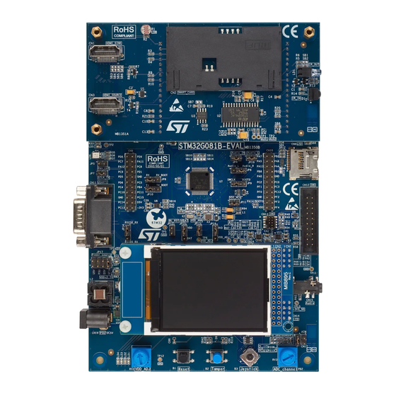
STM32G081B-EVAL board with
Figure 1.
legacy peripheral daughterboard
Pictures are not contractual.
™
card, CEC on two HDMI connectors, smartcard
STM32G081B-EVAL board with
Figure 2.
UCPD daughterboard
UM2403 Rev 1
UM2403
User manual
®
1/78
www.st.com
1
Advertisement
Table of Contents

Related Manuals for ST STM32G081B-EVAL


Summary of Contents for ST STM32G081B-EVAL
- Page 1 12-bit DACs, two GP comparators, two LP timers, internal 32KB SRAM and 128KB Flash, CEC, SWD debugging support. The full range of hardware features on the STM32G081B-EVAL Evaluation board includes the mother board, the legacy peripheral daughterboard and the USB Type-C and Power...
-
Page 2: Table Of Contents
Embedded ST-LINK/V2-1 ........15... - Page 3 Daughterboard connector CN4 and CN5 ......32 9.1.4 ST-LINK/V2-1 USB Micro-B connector CN6 ..... 34 9.1.5 ST-LINK/V2-1 programming connector CN7 .
- Page 4 Appendix A Electrical schematics ........47 Appendix B STM32G081B-EVAL IO Assignment ......72 Appendix C Federal Communications Commission (FCC) and Industry Canada (IC) Compliance Statements .
- Page 5 STM32G081B-EVAL IO Assignment ........
- Page 6 STM32G081B-EVAL extension connectors ........56...
- Page 7 STM32G081B-EVAL UCPD daughterboard USB PD......69 Figure 51. STM32G081B-EVAL UCPD daughterboard power ......70 Figure 52.
-
Page 8: Features
5 V power jack – ST-LINK/V2-1 USB connector – Daughterboard • On-board ST-LINK/V2-1 debugger/programmer with USB enumeration capability: mass storage, virtual COM port and debug port • Comprehensive free software libraries and examples available with the STM32Cube package • Support of a wide choice of Integrated Development Environments (IDEs) including ®... - Page 9 UM2403 Features Legacy peripheral daughterboard • IrDA transceiver • IR LED and IR receiver • Light dependent resistor (LDR) • Temperature Sensor • Board connectors: – Two HDMI connectors with DDC and CEC – Smartcard slot USB Type-C and Power Delivery daughterboard •...
-
Page 10: Product Marking
• on the targeted STM32 that is soldered on the board (for illustration of STM32 marking, refer to the section Package information in the STM32 datasheet at www.st.com). • next to the evaluation tool ordering part number, that is stuck or silkscreen printed on... -
Page 11: Ordering Information
UM2403 Ordering information Ordering information To order the STM32G081B-EVAL Evaluation board, refer to Table Table 1. Ordering information Order code Target STM32 STM32G081B-EVAL STM32G081RB Delivery recommendations Some verifications are needed before using the board for the first time, to make sure that no damage occurred during shipment and that no components are unplugged or lost. -
Page 12: Hardware Layout And Configuration
Hardware layout and configuration UM2403 Hardware layout and configuration The STM32G081B-EVAL Evaluation board is designed around the STM32G081RBT6 (64- pin LQFP package). The hardware block diagram Figure 3 illustrates the connection between STM32G081RBT6 and peripherals (motor control connector, RS232, RS485, Audio DAC, microphone ADC, TFT LCD, CAN, IrDA, IR LED, IR receiver, LDR, MicroSD card, CEC on two HDMI connectors, Smartcard slot, Temperature sensor…... -
Page 13: Figure 4. Stm32G081B-Eval Evaluation Board Layout
UM2403 Hardware layout and configuration Figure 4. STM32G081B-EVAL Evaluation board layout UM2403 Rev 1 13/78 Arrow.com. Arrow.com. Arrow.com. Arrow.com. Arrow.com. Arrow.com. Arrow.com. Arrow.com. Arrow.com. Arrow.com. Arrow.com. Arrow.com. Arrow.com. Downloaded from Downloaded from Downloaded from Downloaded from Downloaded from Downloaded from... -
Page 14: Figure 5. Legacy Peripheral Daughterboard
Hardware layout and configuration UM2403 Figure 5. Legacy peripheral daughterboard Figure 6. USB Type-C and Power Delivery daughterboard 14/78 UM2403 Rev 1 Arrow.com. Arrow.com. Arrow.com. Arrow.com. Arrow.com. Arrow.com. Arrow.com. Arrow.com. Arrow.com. Arrow.com. Arrow.com. Arrow.com. Arrow.com. Arrow.com. Downloaded from Downloaded from Downloaded from Downloaded from Downloaded from... -
Page 15: Embedded St-Link/V2-1
STM32 User manual (UM1075) in the www.st.com website. Note: It is possible to power the board via CN6 (Embedded ST-LINK/V2-1 USB connector) even if an external tools is connected to CN12 or CN13 (External SWD connector). 8.1.1 Drivers The ST-LINK/V2-1 requires a dedicated USB driver, which can be found on www.st.com... -
Page 16: Power Supply
UM2403 Power supply The STM32G081B-EVAL Evaluation mother board is designed to be powered by 5 V DC power supply and is protected by PolyZen from wrong power plug-in event. It is possible to configure the mother board to use any of the following four sources for the power supply: •... -
Page 17: Figure 8. 5 V Power Structure
E5V (from PSU) or D5V can be used as external power supply in case current consumption of the STM32G081B-EVAL board exceeds the allowed current on USB. In this condition it is still possible to use USB for communication, for programming or debugging only, but it is mandatory to power the board first using E5V or D5V, and then connecting the USB cable to the PC. -
Page 18: Table 2. Power Source Related Jumpers
Consequently the board is not powered (LED LD7 remains OFF). In case the STM32G081B-EVAL board is powered by an USB charger through CN6, there is no USB enumeration needed. User can set JP17 to U5V to allow the board to be powered anyway from CN6. -
Page 19: Table 3. Low Voltage Limitation
Note: The UCPD daughterboard works with VDD=3.3V, so it is mandatory to close JP16 pin1 and pin2. The LED LD7 is lit when the STM32G081B-EVAL Evaluation board is powered by the 5V correctly. Table 3 shows the low voltage limitations that might apply depending on the characteristics of some peripheral components. -
Page 20: Clock References
PF1 is connected to extension connector CN10 when SB21 is closed. In such case R46 must be removed to avoid disturbance due to the 8Mhz quartz. Reset source The general reset of the STM32G081B-EVAL Evaluation board is active low and the reset sources include: •... -
Page 21: Boot Option
8.6.1 Audio The STM32G081B-EVAL Evaluation board supports stereo audio playback and microphone recording by an external headset connected on audio jack CN15. Audio play is connected to DAC output of STM32G081RBT6 through an audio amplifier and microphone on headset is connected to ADC input of STM32G081RBT6 through a microphone amplifier. -
Page 22: Rs232 And Rs485
Communication through RS232 (with Hardware flow control CTS and RTS) and RS485 is supported by D-type 9-pins RS232/RS485 connector CN11, which is connected to USART1 of STM32G081RBT6 on STM32G081B-EVAL Evaluation board. The signal Bootloader_RESET (shared with CTS signal) and Bootloader_BOOT0 (shared with DSR signal) are added on RS232 connector CN11 for ISP support. -
Page 23: Microsd Card
8.6.5 External I2C Connector The I2C1 bus of the STM32G081RBT6 is connected to CN2 on the STM32G081B-EVAL. The I2C functional daughterboard can be mounted on the CN2 connector and accessed by the microcontroller through the I2C1 bus, it shares same I2C1 bus with Temperature sensor U3 and DDC on HDMI_Source connector CN3 on legacy peripheral daughterboard. -
Page 24: Motor Control
VDD. 8.6.6 Motor Control The STM32G081B-EVAL Evaluation board supports both asynchronous and synchronous three-phase brushless motor control via a 34-pins connector CN1, which provides all required control and feedback signals to and from motor power-driving board. Available signals on this connector includes emergency stop, motor speed, 3 phase motor current, bus voltage, power heatsink coming from the motor driving board and 6 channels of PWM control signal going to the motor driving circuit. -
Page 25: Peripherals On Legacy Peripheral Daughterboard
The VDD is divided by resistor bridge of LDR VT9ON1 and 8.2 K resistor and connected to PA1 (COM1_IN+/ADC IN1) as shown Figure 9 on STM32G081B-EVAL Evaluation board. Figure 9. GP comparator 1 It's possible to compare LDR output with ¼ band gap, 1/2 band gap, 3/4 band gap, band gap and DAC1 OUT and to connect LDR output to ADC IN1 for AD conversion. -
Page 26: Smartcard
5V/3V pin. Smartcard operates correctly when VDD > 2.7 V. 8.7.4 HDMI CEC Two HDMI connectors CN1 and CN3 are available on STM32G081B-EVAL legacy peripheral daughterboard. • The connector CN1 is HDMI sink connector with –... -
Page 27: Ir Led And Ir Receiver
USB Type-C and Power Delivery daughterboard The UCPD daughterboard is a development platform composed of STM32G081B-EVAL Evaluation board. This daughterboard is used for demonstrating the functionalities of the USB Type-C and USB Power Delivery (USB PD) technologies, facilitating the users to develop their solutions. -
Page 28: Power Delivery And Local Power Management
The UCPD daughterboard has its own external power jack (CN3, 19V/4A input) to support power delivery function and to provide up to 15V/3A on Type-C port1 (CN7). The STM32G081B-EVAL Evaluation board can be powered by D5V from the UCPD daughterboard as shown in Figure 5. -
Page 29: Vbus Voltage-Sensing And Current-Sense Stage
UM2403 Hardware layout and configuration Table 16. VBUS Power Delivery profiles Source Solder bridges CN7 role Power level control Voltage control signal setting signal SB2, SB3, SB23, SB26 ON PWM Mode: PD3 High PC1-PWM signal PWM voltage-3A SB13, SB14, SB15 5V: PC1(VSOURCE- Provider 9V) and... -
Page 30: Table 18. Dead Battery Related Jumpers
Hardware layout and configuration UM2403 embedded in STM32G081RBT6. When OVP part U17 is bypassed, dead battery function in STM32G081RBT6 can be enable or disable through enable signals by set JP2 (CC1) or JP1 (CC2). Refer to Table 18 for detail. Table 18. -
Page 31: Connectors
UM2403 Connectors Connectors Connectors on mother board 9.1.1 Motor control connector CN1 Figure 10. Motor Control connector CN1 (top view) Table 19. Motor control connector CN1 Pin of Pin of Description number of number of Description STM32G081RBT6 STM32G081RBT6 Emergency STOP PB12 PWM-UH PWM-UL PWM-VH... -
Page 32: External I2C Connector Cn2
All GPI/Os are available on CN4, CN5 and extension connector CN9, CN10. Each pin on CN4 and CN5 can be used by a daughterboard after disconnecting it from the corresponding function block on STM32G081B-EVAL Evaluation board. Please refer to Table 21 Table 22 for detail. - Page 33 UM2403 Connectors Table 21. Daughterboard connector CN4 Legacy UCPD How to disconnect with Mother board Signal daughterboard daughterboard function block on mother Function Function (CN5) Function (CN9) board MC_BusVoltage LDR_OUT V_CTL2 Keep JP1 open PA15 Smartcard RST USB3_DET I2C1_SCL I2C1_SCL I2C1_SCL I2C1_SDA I2C1_SDA...
-
Page 34: St-Link/V2-1 Usb Micro-B Connector Cn6
Power of CN2 9.1.4 ST-LINK/V2-1 USB Micro-B connector CN6 The USB Micro-B connector CN6 is used to connect embedded ST-LINK/V2-1 to PC for debugging of board. Figure 12. USB Micro-B connector CN6 (front view) Table 23. USB Micro-B connector CN6... -
Page 35: St-Link/V2-1 Programming Connector Cn7
UM2403 Connectors 9.1.5 ST-LINK/V2-1 programming connector CN7 The connector CN7 is used only for embedded ST-LINK/V2-1 programming during board manufacturing. It is not populated by default and not for end user. 9.1.6 microSD connector CN8 Figure 13. microSD connector CN8 (front view) Table 24. -
Page 36: Table 25. Extension Connector Cn9
Connectors UM2403 Table 25. Extension connector CN9 How to disconnect with function block on Description Alternative Function STM32G081B-EVAL board LED3 Close SB11, Open SB14, SB34 GPIO_JOY_RIGHT Open SB40 PA12 USART_1_RTS Open SB16 GPIO_SD_DETECT Open SB8 LED1 Open SB36 LED2 Open SB35... -
Page 37: Rs232 And Rs485 Connector Cn11
UM2403 Connectors Table 26. Extension connector CN10 (continued) How to disconnect with function block on Description Alternative Function STM32G081B-EVAL board PA14-BOOT SWCLK || BOOT0 Open JP9 pin1-2 POTENTIOMETER_ADC_IN10 Open SB43 AUDIO_IN_ADC_IN6/ Open JP4, Keep CN1 disconnected MC_CurrentB AUDIO_OUT_DAC1_OUT1 Open JP6 pin1-2, JP19... -
Page 38: Standard Swd Connector Cn12
Connectors UM2403 Table 27. RS232 & RS485 connector CN11 (continued) Pin number Description Description number RS485_A RS485_B 9.1.9 Standard SWD connector CN12 Figure 15. Standard SWD debugging connector CN12 (top view) Table 28. Standard SWD debugging connector CN12 Pin number Description Description number... -
Page 39: High Density Swd Connector Cn13
A 3.5mm Stereo audio jack CN15 connected to audio DAC and ADC is available on STM32G081B-EVAL board. 9.1.13 5 V Power connector CN16 STM32G081B-EVAL Evaluation mother board can be powered from a DC 5V power supply via the external power supply jack (CN16) shown in Figure 17. The central pin of CN16 must be positive. -
Page 40: Analog Input Connector Cn17
Connectors UM2403 9.1.14 Analog input connector CN17 Figure 18. Analog input-output connector CN17 (top view) Table 30. Analog input-output connector CN17 Pin number Description Description number Analog input-output PB2 Connectors on legacy peripheral daughterboard 9.2.1 HDMI sink connector CN1 Figure 19. HDMI sink connector CN1 (front view) Table 31. -
Page 41: Smartcard Connector Cn2
UM2403 Connectors 9.2.2 Smartcard connector CN2 Figure 20. Smartcard connector CN2 (top view) Table 32. Smartcard connector CN2 Pin number Description Description number Card presence detection pin Card presence detection pin UM2403 Rev 1 41/78 Arrow.com. Arrow.com. Arrow.com. Arrow.com. Arrow.com. Arrow.com. -
Page 42: Hdmi Source Connector Cn3
Connectors UM2403 9.2.3 HDMI source connector CN3 Figure 21. HDMI source connector CN3 (front view) Table 33. HDMI source connector CN3 Pin number Description Pin number Description TMDS differential signal pair 1,3,4,6,7,9,10,12 I2C1_SDA (PB7) connected to CN1 CEC (PB10) 2,5,8,11,17 HDMI_5V_Source from power switch U3 I2C1_SCL (PB6) -
Page 43: Displayport Source Connector Cn2
UM2403 Connectors 9.3.2 DisplayPort source connector CN2 Figure 23. DisplayPort source connector CN2 (front view) Table 35. DisplayPort source connector CN2 Pin number Description Pin number Description LANE0_P CONFIG1 LANE0_N CONFIG2 LANE1_P AUX_CH_P LANE1_N AUX_CH_N LANE2_P HPD (PC6) LANE2_N RETURN LANE3_P DP_PWR LANE3_N... -
Page 44: Usb3.1 Gen1 Type B Connector Cn4
Connectors UM2403 9.3.4 USB3.1 Gen1 Type B connector CN4 Figure 25. USB3.1 Gen1 Type B connector CN4 (front view) Table 36. USB3.1 Gen1 Type B connector CN4 Pin number Description Pin number Description VBUS (power) SSTX- SSTX+ GND_DRAIN SSRX- SSRX+ 9.3.5 USB Type-C connector PORT2 CN5 Figure 26. -
Page 45: Display Port Sink Connector Cn6
UM2403 Connectors Table 37. USB Type-C connector PORT2 CN5 (continued) Pin number Description Pin number Description SBU1 SBU2 VBUS VBUS RX2- RX1- RX2+ RX1+ 9.3.6 Display port sink connector CN6 Figure 27. DisplayPort sink connector CN6 (front view) Table 38. DisplayPort sink connector CN6 Pin number Description Pin number... -
Page 46: Usb Type-C Connector Port1 Cn7
Connectors UM2403 9.3.7 USB Type-C connector PORT1 CN7 Figure 28. USB Type-C connector PORT1 CN7 (front view) Table 39. USB Type-C connector PORT1 CN7 Pin number Description Pin number Description TX1+ TX2+ TX1- TX2- VBUS VBUS CC1 (PA8) CC2 (PB15) SBU1 SBU2 VBUS... -
Page 47: Appendix A Electrical Schematics
UM2403 Electrical schematics Appendix A Electrical schematics This chapter provides design schematics for the STM32G081B-EVAL key features to help users to implement these features in application designs: • Figure 29: STM32G081B-EVAL mother board top on page 48 • Figure 30: STM32G081B-EVAL MCU on page 49 •... - Page 48 Electrical schematics UM2403 48/78 UM2403 Rev 1 Arrow.com. Arrow.com. Arrow.com. Arrow.com. Arrow.com. Arrow.com. Arrow.com. Arrow.com. Arrow.com. Arrow.com. Arrow.com. Arrow.com. Arrow.com. Arrow.com. Arrow.com. Arrow.com. Arrow.com. Arrow.com. Arrow.com. Arrow.com. Arrow.com. Arrow.com. Arrow.com. Arrow.com. Arrow.com. Arrow.com. Arrow.com. Arrow.com. Arrow.com. Arrow.com. Arrow.com. Arrow.com. Arrow.com. Arrow.com.
- Page 49 UM2403 Electrical schematics UM2403 Rev 1 49/78 Arrow.com. Arrow.com. Arrow.com. Arrow.com. Arrow.com. Arrow.com. Arrow.com. Arrow.com. Arrow.com. Arrow.com. Arrow.com. Arrow.com. Arrow.com. Arrow.com. Arrow.com. Arrow.com. Arrow.com. Arrow.com. Arrow.com. Arrow.com. Arrow.com. Arrow.com. Arrow.com. Arrow.com. Arrow.com. Arrow.com. Arrow.com. Arrow.com. Arrow.com. Arrow.com. Arrow.com. Arrow.com. Arrow.com. Arrow.com.
- Page 50 Electrical schematics UM2403 50/78 UM2403 Rev 1 Arrow.com. Arrow.com. Arrow.com. Arrow.com. Arrow.com. Arrow.com. Arrow.com. Arrow.com. Arrow.com. Arrow.com. Arrow.com. Arrow.com. Arrow.com. Arrow.com. Arrow.com. Arrow.com. Arrow.com. Arrow.com. Arrow.com. Arrow.com. Arrow.com. Arrow.com. Arrow.com. Arrow.com. Arrow.com. Arrow.com. Arrow.com. Arrow.com. Arrow.com. Arrow.com. Arrow.com. Arrow.com. Arrow.com. Arrow.com.
- Page 51 UM2403 Electrical schematics UM2403 Rev 1 51/78 Arrow.com. Arrow.com. Arrow.com. Arrow.com. Arrow.com. Arrow.com. Arrow.com. Arrow.com. Arrow.com. Arrow.com. Arrow.com. Arrow.com. Arrow.com. Arrow.com. Arrow.com. Arrow.com. Arrow.com. Arrow.com. Arrow.com. Arrow.com. Arrow.com. Arrow.com. Arrow.com. Arrow.com. Arrow.com. Arrow.com. Arrow.com. Arrow.com. Arrow.com. Arrow.com. Arrow.com. Arrow.com. Arrow.com. Arrow.com.
- Page 52 Electrical schematics UM2403 52/78 UM2403 Rev 1 Arrow.com. Arrow.com. Arrow.com. Arrow.com. Arrow.com. Arrow.com. Arrow.com. Arrow.com. Arrow.com. Arrow.com. Arrow.com. Arrow.com. Arrow.com. Arrow.com. Arrow.com. Arrow.com. Arrow.com. Arrow.com. Arrow.com. Arrow.com. Arrow.com. Arrow.com. Arrow.com. Arrow.com. Arrow.com. Arrow.com. Arrow.com. Arrow.com. Arrow.com. Arrow.com. Arrow.com. Arrow.com. Arrow.com. Arrow.com.
- Page 53 UM2403 Electrical schematics UM2403 Rev 1 53/78 Arrow.com. Arrow.com. Arrow.com. Arrow.com. Arrow.com. Arrow.com. Arrow.com. Arrow.com. Arrow.com. Arrow.com. Arrow.com. Arrow.com. Arrow.com. Arrow.com. Arrow.com. Arrow.com. Arrow.com. Arrow.com. Arrow.com. Arrow.com. Arrow.com. Arrow.com. Arrow.com. Arrow.com. Arrow.com. Arrow.com. Arrow.com. Arrow.com. Arrow.com. Arrow.com. Arrow.com. Arrow.com. Arrow.com. Arrow.com.
- Page 54 Electrical schematics UM2403 54/78 UM2403 Rev 1 Arrow.com. Arrow.com. Arrow.com. Arrow.com. Arrow.com. Arrow.com. Arrow.com. Arrow.com. Arrow.com. Arrow.com. Arrow.com. Arrow.com. Arrow.com. Arrow.com. Arrow.com. Arrow.com. Arrow.com. Arrow.com. Arrow.com. Arrow.com. Arrow.com. Arrow.com. Arrow.com. Arrow.com. Arrow.com. Arrow.com. Arrow.com. Arrow.com. Arrow.com. Arrow.com. Arrow.com. Arrow.com. Arrow.com. Arrow.com.
- Page 55 UM2403 Electrical schematics UM2403 Rev 1 55/78 Arrow.com. Arrow.com. Arrow.com. Arrow.com. Arrow.com. Arrow.com. Arrow.com. Arrow.com. Arrow.com. Arrow.com. Arrow.com. Arrow.com. Arrow.com. Arrow.com. Arrow.com. Arrow.com. Arrow.com. Arrow.com. Arrow.com. Arrow.com. Arrow.com. Arrow.com. Arrow.com. Arrow.com. Arrow.com. Arrow.com. Arrow.com. Arrow.com. Arrow.com. Arrow.com. Arrow.com. Arrow.com. Arrow.com. Arrow.com.
- Page 56 Electrical schematics UM2403 56/78 UM2403 Rev 1 Arrow.com. Arrow.com. Arrow.com. Arrow.com. Arrow.com. Arrow.com. Arrow.com. Arrow.com. Arrow.com. Arrow.com. Arrow.com. Arrow.com. Arrow.com. Arrow.com. Arrow.com. Arrow.com. Arrow.com. Arrow.com. Arrow.com. Arrow.com. Arrow.com. Arrow.com. Arrow.com. Arrow.com. Arrow.com. Arrow.com. Arrow.com. Arrow.com. Arrow.com. Arrow.com. Arrow.com. Arrow.com. Arrow.com. Arrow.com.
- Page 57 UM2403 Electrical schematics UM2403 Rev 1 57/78 Arrow.com. Arrow.com. Arrow.com. Arrow.com. Arrow.com. Arrow.com. Arrow.com. Arrow.com. Arrow.com. Arrow.com. Arrow.com. Arrow.com. Arrow.com. Arrow.com. Arrow.com. Arrow.com. Arrow.com. Arrow.com. Arrow.com. Arrow.com. Arrow.com. Arrow.com. Arrow.com. Arrow.com. Arrow.com. Arrow.com. Arrow.com. Arrow.com. Arrow.com. Arrow.com. Arrow.com. Arrow.com. Arrow.com. Arrow.com.
- Page 58 Electrical schematics UM2403 58/78 UM2403 Rev 1 Arrow.com. Arrow.com. Arrow.com. Arrow.com. Arrow.com. Arrow.com. Arrow.com. Arrow.com. Arrow.com. Arrow.com. Arrow.com. Arrow.com. Arrow.com. Arrow.com. Arrow.com. Arrow.com. Arrow.com. Arrow.com. Arrow.com. Arrow.com. Arrow.com. Arrow.com. Arrow.com. Arrow.com. Arrow.com. Arrow.com. Arrow.com. Arrow.com. Arrow.com. Arrow.com. Arrow.com. Arrow.com. Arrow.com. Arrow.com.
- Page 59 UM2403 Electrical schematics UM2403 Rev 1 59/78 Arrow.com. Arrow.com. Arrow.com. Arrow.com. Arrow.com. Arrow.com. Arrow.com. Arrow.com. Arrow.com. Arrow.com. Arrow.com. Arrow.com. Arrow.com. Arrow.com. Arrow.com. Arrow.com. Arrow.com. Arrow.com. Arrow.com. Arrow.com. Arrow.com. Arrow.com. Arrow.com. Arrow.com. Arrow.com. Arrow.com. Arrow.com. Arrow.com. Arrow.com. Arrow.com. Arrow.com. Arrow.com. Arrow.com. Arrow.com.
- Page 60 Electrical schematics UM2403 60/78 UM2403 Rev 1 Arrow.com. Arrow.com. Arrow.com. Arrow.com. Arrow.com. Arrow.com. Arrow.com. Arrow.com. Arrow.com. Arrow.com. Arrow.com. Arrow.com. Arrow.com. Arrow.com. Arrow.com. Arrow.com. Arrow.com. Arrow.com. Arrow.com. Arrow.com. Arrow.com. Arrow.com. Arrow.com. Arrow.com. Arrow.com. Arrow.com. Arrow.com. Arrow.com. Arrow.com. Arrow.com. Arrow.com. Arrow.com. Arrow.com. Arrow.com.
- Page 61 UM2403 Electrical schematics UM2403 Rev 1 61/78 Arrow.com. Arrow.com. Arrow.com. Arrow.com. Arrow.com. Arrow.com. Arrow.com. Arrow.com. Arrow.com. Arrow.com. Arrow.com. Arrow.com. Arrow.com. Arrow.com. Arrow.com. Arrow.com. Arrow.com. Arrow.com. Arrow.com. Arrow.com. Arrow.com. Arrow.com. Arrow.com. Arrow.com. Arrow.com. Arrow.com. Arrow.com. Arrow.com. Arrow.com. Arrow.com. Arrow.com. Arrow.com. Arrow.com. Arrow.com.
- Page 62 Electrical schematics UM2403 62/78 UM2403 Rev 1 Arrow.com. Arrow.com. Arrow.com. Arrow.com. Arrow.com. Arrow.com. Arrow.com. Arrow.com. Arrow.com. Arrow.com. Arrow.com. Arrow.com. Arrow.com. Arrow.com. Arrow.com. Arrow.com. Arrow.com. Arrow.com. Arrow.com. Arrow.com. Arrow.com. Arrow.com. Arrow.com. Arrow.com. Arrow.com. Arrow.com. Arrow.com. Arrow.com. Arrow.com. Arrow.com. Arrow.com. Arrow.com. Arrow.com. Arrow.com.
- Page 63 UM2403 Electrical schematics UM2403 Rev 1 63/78 Arrow.com. Arrow.com. Arrow.com. Arrow.com. Arrow.com. Arrow.com. Arrow.com. Arrow.com. Arrow.com. Arrow.com. Arrow.com. Arrow.com. Arrow.com. Arrow.com. Arrow.com. Arrow.com. Arrow.com. Arrow.com. Arrow.com. Arrow.com. Arrow.com. Arrow.com. Arrow.com. Arrow.com. Arrow.com. Arrow.com. Arrow.com. Arrow.com. Arrow.com. Arrow.com. Arrow.com. Arrow.com. Arrow.com. Arrow.com.
- Page 64 Electrical schematics UM2403 64/78 UM2403 Rev 1 Arrow.com. Arrow.com. Arrow.com. Arrow.com. Arrow.com. Arrow.com. Arrow.com. Arrow.com. Arrow.com. Arrow.com. Arrow.com. Arrow.com. Arrow.com. Arrow.com. Arrow.com. Arrow.com. Arrow.com. Arrow.com. Arrow.com. Arrow.com. Arrow.com. Arrow.com. Arrow.com. Arrow.com. Arrow.com. Arrow.com. Arrow.com. Arrow.com. Arrow.com. Arrow.com. Arrow.com. Arrow.com. Arrow.com. Arrow.com.
- Page 65 UM2403 Electrical schematics UM2403 Rev 1 65/78 Arrow.com. Arrow.com. Arrow.com. Arrow.com. Arrow.com. Arrow.com. Arrow.com. Arrow.com. Arrow.com. Arrow.com. Arrow.com. Arrow.com. Arrow.com. Arrow.com. Arrow.com. Arrow.com. Arrow.com. Arrow.com. Arrow.com. Arrow.com. Arrow.com. Arrow.com. Arrow.com. Arrow.com. Arrow.com. Arrow.com. Arrow.com. Arrow.com. Arrow.com. Arrow.com. Arrow.com. Arrow.com. Arrow.com. Arrow.com.
- Page 66 Electrical schematics UM2403 66/78 UM2403 Rev 1 Arrow.com. Arrow.com. Arrow.com. Arrow.com. Arrow.com. Arrow.com. Arrow.com. Arrow.com. Arrow.com. Arrow.com. Arrow.com. Arrow.com. Arrow.com. Arrow.com. Arrow.com. Arrow.com. Arrow.com. Arrow.com. Arrow.com. Arrow.com. Arrow.com. Arrow.com. Arrow.com. Arrow.com. Arrow.com. Arrow.com. Arrow.com. Arrow.com. Arrow.com. Arrow.com. Arrow.com. Arrow.com. Arrow.com. Arrow.com.
- Page 67 UM2403 Electrical schematics UM2403 Rev 1 67/78 Arrow.com. Arrow.com. Arrow.com. Arrow.com. Arrow.com. Arrow.com. Arrow.com. Arrow.com. Arrow.com. Arrow.com. Arrow.com. Arrow.com. Arrow.com. Arrow.com. Arrow.com. Arrow.com. Arrow.com. Arrow.com. Arrow.com. Arrow.com. Arrow.com. Arrow.com. Arrow.com. Arrow.com. Arrow.com. Arrow.com. Arrow.com. Arrow.com. Arrow.com. Arrow.com. Arrow.com. Arrow.com. Arrow.com. Arrow.com.
- Page 68 Electrical schematics UM2403 68/78 UM2403 Rev 1 Arrow.com. Arrow.com. Arrow.com. Arrow.com. Arrow.com. Arrow.com. Arrow.com. Arrow.com. Arrow.com. Arrow.com. Arrow.com. Arrow.com. Arrow.com. Arrow.com. Arrow.com. Arrow.com. Arrow.com. Arrow.com. Arrow.com. Arrow.com. Arrow.com. Arrow.com. Arrow.com. Arrow.com. Arrow.com. Arrow.com. Arrow.com. Arrow.com. Arrow.com. Arrow.com. Arrow.com. Arrow.com. Arrow.com. Arrow.com.
- Page 69 UM2403 Electrical schematics UM2403 Rev 1 69/78 Arrow.com. Arrow.com. Arrow.com. Arrow.com. Arrow.com. Arrow.com. Arrow.com. Arrow.com. Arrow.com. Arrow.com. Arrow.com. Arrow.com. Arrow.com. Arrow.com. Arrow.com. Arrow.com. Arrow.com. Arrow.com. Arrow.com. Arrow.com. Arrow.com. Arrow.com. Arrow.com. Arrow.com. Arrow.com. Arrow.com. Arrow.com. Arrow.com. Arrow.com. Arrow.com. Arrow.com. Arrow.com. Arrow.com. Arrow.com.
- Page 70 Electrical schematics UM2403 70/78 UM2403 Rev 1 Arrow.com. Arrow.com. Arrow.com. Arrow.com. Arrow.com. Arrow.com. Arrow.com. Arrow.com. Arrow.com. Arrow.com. Arrow.com. Arrow.com. Arrow.com. Arrow.com. Arrow.com. Arrow.com. Arrow.com. Arrow.com. Arrow.com. Arrow.com. Arrow.com. Arrow.com. Arrow.com. Arrow.com. Arrow.com. Arrow.com. Arrow.com. Arrow.com. Arrow.com. Arrow.com. Arrow.com. Arrow.com. Arrow.com. Arrow.com.
- Page 71 UM2403 Electrical schematics UM2403 Rev 1 71/78 Arrow.com. Arrow.com. Arrow.com. Arrow.com. Arrow.com. Arrow.com. Arrow.com. Arrow.com. Arrow.com. Arrow.com. Arrow.com. Arrow.com. Arrow.com. Arrow.com. Arrow.com. Arrow.com. Arrow.com. Arrow.com. Arrow.com. Arrow.com. Arrow.com. Arrow.com. Arrow.com. Arrow.com. Arrow.com. Arrow.com. Arrow.com. Arrow.com. Arrow.com. Arrow.com. Arrow.com. Arrow.com. Arrow.com. Arrow.com.
-
Page 72: Appendix Bstm32G081B-Eval Io Assignment
STM32G081B-EVAL IO Assignment UM2403 Appendix B STM32G081B-EVAL IO Assignment Table 40. STM32G081B-EVAL IO Assignment IO Assignment on mother IO Assignment on IO Assignment on UCPD Pin Name board legacy daughterboard daughterboard PC11 VCP_USART_3_RX PC12 GPIO_LCD / SD_MOSI_DIR KEY_TAMP_IN1, RTC_TS, PC13... - Page 73 UM2403 STM32G081B-EVAL IO Assignment Table 40. STM32G081B-EVAL IO Assignment (continued) IO Assignment on mother IO Assignment on IO Assignment on UCPD Pin Name board legacy daughterboard daughterboard LCD/SD1_MOSI USART_1_TX USART_1_RX MC_TIM_3_CH3(Encoder GPIO_SMART_CMDVCC TYPE-C_1_FRSTX index) MC_TIM_3_CH4(PFC_PWM) - TYPE-C_1_V_ADC_IN9 POT_ADC_IN10 PB10 MC_ADC_IN11(CurrentC)
- Page 74 STM32G081B-EVAL IO Assignment UM2403 Table 40. STM32G081B-EVAL IO Assignment (continued) IO Assignment on mother IO Assignment on IO Assignment on UCPD Pin Name board legacy daughterboard daughterboard GPIO_SD_CS MC_TIM_1_CH1N(UL) GPIO_HDMI_HPD_SINK TYPE-C_2_CC2 GPIO_HDMI_HPD_SOUR MC_TIM_1_CH2N(VL) GPIO_SOURCE_EN MC_TIM_1_CH3N(WL) SMART_2_RTS_DE_CK GPIO_VCONN_EN_1_1 LED1 LED2 LCD/SD1_SCK...
-
Page 75: Appendix C Federal Communications Commission (Fcc) And Industry Canada (Ic) Compliance Statements
UM2403Federal Communications Commission (FCC) and Industry Canada (IC) Compliance State- Appendix C Federal Communications Commission (FCC) Industry Canada (IC) Compliance Statements FCC Compliance Statement C.1.1 Part 15.19 This device complies with Part 15 of the FCC Rules. Operation is subject to the following two conditions: (1) this device may not cause harmful interference, and (2) this device must accept any interference received, including interference that may cause undesired operation. -
Page 76: Appendix D Mechanical Dimensions
Mechanical dimensions UM2403 Appendix D Mechanical dimensions Figure 53. Mechanical dimensions Table 41. Mechanical dimensions Symbol Size (mm) Symbol Size (mm) Symbol Size (mm) 68.58 77.44 111.76 61.97 10.41 2.54 5.715 24.12 5.715 17.70 19.08 23.81 114.3 65.78 172.72 76/78 UM2403 Rev 1 Arrow.com. -
Page 77: Revision History
UM2403 Revision history Revision history Table 42. Document revision history Date Revision Changes 7-Nov-2018 Initial version UM2403 Rev 1 77/78 Arrow.com. Arrow.com. Arrow.com. Arrow.com. Arrow.com. Arrow.com. Arrow.com. Arrow.com. Arrow.com. Arrow.com. Arrow.com. Arrow.com. Arrow.com. Arrow.com. Arrow.com. Arrow.com. Arrow.com. Arrow.com. Arrow.com. Arrow.com. Arrow.com. - Page 78 ST products and/or to this document at any time without notice. Purchasers should obtain the latest relevant information on ST products before placing orders. ST products are sold pursuant to ST’s terms and conditions of sale in place at the time of order acknowledgement.
Need help?
Do you have a question about the STM32G081B-EVAL and is the answer not in the manual?
Questions and answers