Sign In
Upload
Manuals
Brands
ST Manuals
Motherboard
STM32G474E-EVAL
ST STM32G474E-EVAL Manuals
Manuals and User Guides for ST STM32G474E-EVAL. We have
1
ST STM32G474E-EVAL manual available for free PDF download: User Manual
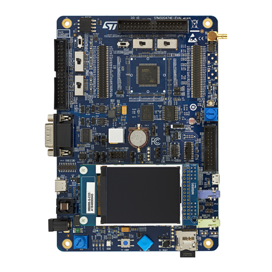
ST STM32G474E-EVAL User Manual (66 pages)
Evaluation board with STM32G4xxQE MCU
Brand:
ST
| Category:
Motherboard
| Size: 3 MB
Table of Contents
Figure 1. STM32G474E-EVAL Top View
1
Figure 2. STM32G474E-EVAL Bottom View
1
Table of Contents
2
Features
8
Ordering Information
10
Codification
10
Table 1. List of Available Products
10
Table 2. Codification Explanation
10
Development Environment
11
System Requirements
11
Development Toolchains
11
Delivery Recommendations
11
Hardware Layout and Configuration
12
Figure 3. Hardware Block Diagram
12
Figure 4. STM32G474E-EVAL Evaluation Board Layout (Top View)
13
Figure 5. STM32G474E-EVAL Evaluation Board Layout (Bottom View)
14
Figure 6. STM32G474E-EVAL Evaluation Board Mechanical Dimensions (Top View)
15
Stlink-V3E
16
Drivers and Firmware Upgrade
16
ETM Trace
16
Table 3. Setting of Configuration Elements for CN17 Trace Connector
16
Table 4. Setting of Configuration I/Os for PE2, PE3, PE4, and PE5
17
Power Supply
18
Supplying the Board through the STLINK-V3E USB Port
19
Using STLINK-V3E Along with Powering through the CN25 Power Jack
19
Table 5. Power-Supply-Related Jumper and Solder Bridge Settings
20
Clock References
21
Table 6. X3 Crystal-Related Solder Bridge Settings
21
Table 7. X2 Crystal-Related Solder Bridge Settings
21
Reset Source
22
Boot Option
22
Limitations
22
Audio
22
Table 8. Boot Selection Switch
22
Limitations in Using Audio Features
23
USB FS Port
23
Operating Voltage
23
RS232 and RS485 Port
23
Limitations
23
Operating Voltage
24
Microsd™ Card
24
Limitations
24
Motor Control
24
Table 9. Configuration PA10 of STM32G474QET6 Terminals
24
Table 10. CN2 Motor-Control Terminal and Function Assignment
25
Table 11. CN4 Motor-Control Terminal and Function Assignment
26
Table 12. Motor Control Opamp and DAC Function Assignment
29
Table 13. Motor-Control-Related Switches and Solder Bridges
30
Board Modifications to Enable Motor Control
31
Limitations
31
Table 14. Motor-Control-Related Switches and Solder Bridges
31
Fdcan
32
Figure 7. PCB Top Side Rework for Motor Control
32
Figure 8. PCB Bottom Side Rework for Motor Control
32
Limitations
33
Operating Voltage
33
CN5 and CN6 Extension Connectors
33
User Leds
33
Physical Input Devices
33
Limitations
34
Operational Amplifier and Comparator
34
Operational Amplifier
34
Table 15. Port Assignment for Control of Physical Input Devices
34
Table 16. Configuration Elements Related to Opamp4
34
Comparator
35
Limitations
35
Table 17. Configuration Elements Related to Comp4
35
Analog Input, Output, VREF
36
Analog Input
36
Analog Output
36
VREF+ Terminal
36
Limitations
37
SRAM Device
37
Operating Voltage
37
EXT_I2C Connector
37
Quad-SPI Flash Memory Device
37
Table 18. Configuration Elements Related to VREF
37
Limitations
38
Operating Voltage
38
Mfx Mcu
38
Mfx
38
IDD Measurement
38
Table 19. MFX Signals
38
Limitations
39
TFT LCD Panel
39
Table 20. IDD Measurement-Related Jumper Settings
39
Table 21. CN20 and CN24 TFT LCD Connectors
39
Ucpd
40
USB Type-C ® Receptacles
40
Power Delivery and Local Power Management
40
VBUS Management and Discharge Mechanism
40
VBUS Voltage-Sensing
41
CC Management
41
Limitations
41
Temperature Sensor
41
Table 22. Dead-Battery Related Jumpers
41
Operating Voltage
42
Smartcard
42
High-Brightness LED
42
Limitations
42
Table 23. Connection between ST8024L and STM32F091VCT6
42
Connectors
43
CN1 External I C Connector
43
CN2 and CN4 Motor-Control Connectors
43
Table 24. CN1 EXT_I2C Connector
43
Table 25. CN2 Motor-Control Connector
43
Figure 9. CN1 I 2 C EXT Connector (Front View)
43
Figure 10. CN2 and CN4 Motor-Control Connectors (Front View)
43
Table 26. CN4 Motor-Control Connector
44
CN3, CN7, and CN8 SMB Connectors
45
CN5 and CN6 Extension Connectors
45
CN9 DAC Connector
45
Table 27. SMB Connector
45
Table 28. CN9 Analog Input-Output Connector
45
Figure 11. SMB Connector (Front View)
45
Figure 12. CN9 Analog Input-Output Connector (Top View)
45
CN12 and CN10 CAN1 and CAN2 Connectors
46
CN11 RS232 and RS485 Connector
46
Table 29. CN10 or CN12 CAN Connector
46
Table 30. CN11 RS-232/RS-485 D-Sub Connector
46
Figure 13. CN10 or CN12 CAN Connector (Front View)
46
Figure 14. CN11 RS232 and RS485 Connector (Front View)
46
CN14 JTAG Connector
47
CN15 TAG Connector
47
Table 31. CN14 JTAG Debugging Connector
47
Table 32. CN15 TAG Debugging Connector
47
Figure 15. CN14 JTAG Debugging Connector
47
CN16 STDC14 Connector
48
CN17 Trace-Debugging Connector
48
Table 33. CN16 STDC14 Debugging Connector
48
Table 34. CN17 Trace-Debugging Connector
48
Figure 16. CN16 STDC14 Debugging Connector (Top View)
48
Figure 17. CN17 Trace-Debugging Connector (Top View)
48
CN128 MFX Programming Connector
49
CN19 Type-C Signals Connector
49
Table 35. CN19 Type-C Signals Connector
49
Figure 18. CN19 Type-C Signals Connector (Top View)
49
CN20 and CN24 LCD Connector
50
CN21 STLINK-V3E USB Micro-B Connector
50
Table 36. CN21 USB Micro-B Connector
50
Figure 19. CN21 USB Micro-B Connector (Front View)
50
CN22 USB Type-C ® Connector
51
CN23 Blue Line-In Audio Jack
51
CN26 Green Line-Out Audio Jack
51
Table 37. CN22 USB Type-C ® Connector
51
Figure 20. CN22 USB Type-C ® Connector (Front View)
51
CN25 Power Connector
52
CN27 STLINK-V3E Programming Connector
52
Table 38. CN26 On-Board Audio Jack Connector
52
Figure 21. CN26 Stereo Headset with a Microphone Jack
52
Figure 22. CN25 Power-Supply Connector (Front View)
52
CN28 Microsd™ Connector
53
Table 39. CN28 Microsd™ Connector
53
Figure 23. CN28 Microsd™ Connector (Front View)
53
CN31 Smartcard Connector
54
Table 40. CN31 Smartcard Connector
54
Figure 24. CN31 Smartcard Connector (Top View)
54
STM32G474E-EVAL I/O Assignment
55
Table 41. STM32G474E-EVAL I/O Assignment
55
STM32G474E-EVAL, STM32G474E-EVAL1, and STM32G484E-EVAL Board Information
60
Product Marking
60
STM32G474E-EVAL, STM32G474E-EVAL1, and STM32G484E-EVAL Product History
61
Table 42. Product History
61
Board Revision History
63
Table 43. Board Revision History
63
Federal Communications Commission (FCC) and Innovation, Science and Economic Development Canada (ISED) Compliance Statements
64
FCC Compliance Statement
64
ISED Compliance Statement
64
Revision History
65
Table 44. Document Revision History
65
Advertisement
Advertisement
Related Products
ST STM32G081B-EVAL
ST STM32G0C1E-EV
ST STM32G070RBT6
ST STM32G0B1RET6
ST STM32G071RBT6
ST STM32G0B1RE
ST STM32 Nucleo-64
ST STM32F412xE Series
ST STM32H747XI MCU
ST STM32H753I-EVAL
ST Categories
Motherboard
Computer Hardware
Microcontrollers
Control Unit
Controller
More ST Manuals
Login
Sign In
OR
Sign in with Facebook
Sign in with Google
Upload manual
Upload from disk
Upload from URL