Table of Contents
Advertisement
Quick Links
UM0426
User manual
STM3210B-EVAL
evaluation board
Introduction
TM
The STM3210B-EVAL is an evaluation board for STMicroelectronic's ARM
Cortex-M3
core-based STM32F10x 128K microcontrollers. It is designed as a complete development
environment for the STM32F10x microcontrollers with full speed USB2.0, CAN2.0A/B
2
compliant interface, two I
C channels, two SPI channels, three USART channels with
smartcard support, internal 20KB SRAM and 128KB Flash, JTAG and SWD debugging.
With a complete range of hardware evaluations features, the STM3210B-EVAL board is
designed to help developers evaluate all device peripherals (such as USB, motor control,
CAN, MicroSD card, smartcard, USART) and develop their own applications. Extension
connectors make it possible to easily connect a daughter board or wrapping board for a
specific application.
This user manual provides information on using the STM3210B-EVAL board and its
hardware features.
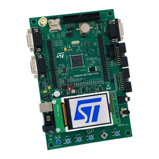
Figure 1.
STM32F10X 128K evaluation board (STM3210B-EVAL)
October 2007
Rev 4
1/46
www.st.com
Advertisement
Table of Contents

Subscribe to Our Youtube Channel
Related Manuals for ST STM3210B-EVAL


Summary of Contents for ST STM3210B-EVAL
-
Page 1: User Manual
C channels, two SPI channels, three USART channels with smartcard support, internal 20KB SRAM and 128KB Flash, JTAG and SWD debugging. With a complete range of hardware evaluations features, the STM3210B-EVAL board is designed to help developers evaluate all device peripherals (such as USB, motor control, CAN, MicroSD card, smartcard, USART) and develop their own applications. -
Page 2: Order Code
● Reset, wakeup, tamper and user push buttons ● 4 LEDs ● RTC with backup battery ● Extension connector for daughter board or wrapping board Order code To order the STM32F10x 128K evaluation board, use the order code STM3210B-EVAL. 2/46... -
Page 3: Table Of Contents
UM0426 Contents Contents Hardware layout and configuration ......5 LCD configuration ..........7 Power supply . - Page 4 Schematics ..........28 Appendix A STM3210B-EVAL IO assignments ......41 Revision history .
-
Page 5: Hardware Layout And Configuration
UM0426 Hardware layout and configuration Hardware layout and configuration The STM3210B-EVAL board is designed around a STM32F103VBT6 microcontroller in a 100-pin LQFP package. The hardware block diagram Figure 2 shows the connections between the STM32F10x microcontroller and peripherals (LCD, SPI Flash, USART, IrDA, USB, Audio, CAN bus, RTC, smartcard, MicroSD card and motor control). - Page 6 Hardware layout and configuration UM0426 Figure 3. STM3210B-EVAL board layout CN12 CN13 STM32F103VBT6 Extension connector Extension connector CN15 CN14 MicroSD card Motor control USART2 CAN connector USART1 CN10 Trace IrDA JTAG Color LCD Audio jack 5V power Potentiometer CN16 RESET...
-
Page 7: Lcd Configuration
Fitted LCD configuration The STM3210B-EVAL can be delivered with either one of two LCDs mounted on the MB542 board, depending on the board version. These two LCDs look alike and operate in the same way, however they have different control circuits, and therefore require different software drivers. - Page 8 STM3210B-EVAL_DEMO version 1.1 or later. It automatically detects which version of the LCD is mounted on the daughter board, and it supports both. If your STM3210B-EVAL product includes the MB542 board version B-00 or earlier, it is mounted with the LCD reference AM-240320LTNQW01H. The controller reference is HX8312-A (from Himax, www.himax.com.tw).
-
Page 9: Power Supply
Hardware layout and configuration Power supply The STM3210B-EVAL board is designed to be powered by 5V DC power supply and to be protected by PolyZen U6 in case of incorrect power supply configuration. It is possible to configure the evaluation board to use any of the following sources for the power supply. -
Page 10: Boot Option
SW2 are set as shown to the right. Boot 0 = 1, Boot 1 = 0 Clock source Two clock sources are available on the STM3210B-EVAL board for the STM32F10X microcontroller and RTC. ● X1, 32KHz crystal for embedded RTC ●... -
Page 11: Reset Source
UM0426 Hardware layout and configuration Reset source The reset signal of the STM3210B-EVAL board is active low and the reset sources include: ● Reset button B1 ● Debugging tools from connector CN7, CN9 and CN10 ● Daughter board from CN13 Table 4. -
Page 12: Motor Control
1.10 Motor control The STM3210B-EVAL board supports induction motor control via a 34-pin connector, CN14, which provides all required control and feedback signals to and from a motor power-drive board. Available signals on this connector include emergency stop, motor speed, 3-phase motor current, bus voltage, heatsink temperature coming from the motor drive board and 6 channels of PWM control signals going to the motor drive circuit. -
Page 13: Smartcard
UM0426 Hardware layout and configuration 1.11 Smartcard The STMicroelectronics smartcard interface device ST8024 is used on the STM3210B- EVAL board for asynchronous 3V and 5V smartcards. It performs all supply protection and control functions based on the connections with the STM32F10X microcontroller, which are listed inTable Table 8. -
Page 14: Irda
Default setting: Fitted 1.16 The STM3210B-EVAL board supports USB2.0 compliant full-speed communication via a USB type B connector (CN1). The evaluation board can be powered by this USB connection at 5V DC with a 500mA current limitation. USB disconnect simulation can be implemented by disconnecting a 1.5K pull-up register from the USB+ line. -
Page 15: Display And Input Devices
A 4-direction joystick with selection key, general purpose pushbutton (B3), wakeup button (B2) and tamper detection button (B4) are available as input devices. The STM3210B-EVAL board also supports a second optional 122x32 graphic LCD that can be mounted on the U19 connector. The graphic LCD is not provided. -
Page 16: Connectors
Connectors UM0426 Connectors USB type B connector CN1 Figure 8. USB type B connector CN1 (front view) Table 12. USB type B connector (CN1) Pin number Description Pin number Description VBUS(power) 5, 6 Shield CAN D-type 9-pin male connector CN2 Figure 9. -
Page 17: Analog Input Connector Cn3
Pin number Description Analog input/PC1 Power supply connector CN4 The STM3210B-EVAL board can be powered from a DC 5V power supply via the external power supply jack (CN4) shown in Figure 11. The central pin of CN4 must be positive. -
Page 18: Rs232 Connector Cn5 With Rts/Cts Handshake Support
Connectors UM0426 RS232 connector CN5 with RTS/CTS handshake support Figure 12. RS232 connector CN5 with RTS/CTS handshake support (front view) Table 15. RS232 connector CN5 with full modem control support Pin number Description Pin number Description Connect to Pin 4 USART2_RXD USART2_RTS USART2_TXD... -
Page 19: Jtag Debugging Connector Cn7
DBGRQ DBGACK Audio jack CN8 A 3.5mm mono audio jack CN8 is available on the STM3210B-EVAL board. The speaker U12 is bypassed when earphones are plugged into CN8. SWD debugging connector CN9 Figure 15. SWD debugging connector CN9 (top view) -
Page 20: Trace Debugging Connector Cn10
Connectors UM0426 Table 18. SWD debugging connector (CN9) Pin number Description Pin number Description +3V3 SWDIO/PA13 SWCLK/PA14 SWO/PB3 TDI/PA15 RESET# 2.10 Trace debugging connector CN10 Figure 16. Trace debugging connector CN10 (front view) 19 17 15 13 11 9 7 5 20 18 16 14 12 10 8 6 Table 19. -
Page 21: Daughter Board Extension Connectors Cn12 And Cn13
Two 50-pin male headers, CN12 and CN13, can be used to connect a daughter board or standard wrapping board to the STM3210B-EVAL board. A total of 80 GPI/Os are available on these connectors. Each pin on CN12 and CN13 can be used by a daughter board after disconnecting it from the corresponding function block on the STM3210B-EVAL board. - Page 22 Daughter board extension connector CN12 (continued) How to disconnect from function block on Description Alternate function STM3210B-EVAL board PD15 Disconnect STM3210B-EVAL board from motor MC connector pin 26 power drive board Disconnect STM3210B-EVAL board from motor MC connector pin 17 power drive board...
- Page 23 UM0426 Connectors Table 20. Daughter board extension connector CN12 (continued) How to disconnect from function block on Description Alternate function STM3210B-EVAL board +3V3 Table 21. Daughter board extension connector CN13 How to disconnect from component on Description Alternate function STM3210B-EVAL board...
-
Page 24: Motor Control Connector Cn14
Joystick Right Remove R75 Speaker Unfitted JP6 Temperature sensor Remove R113 Temperature sensor Remove R112 Debug SWO USART2 Disconnect STM3210B-EVAL board from motor MC connector pin 27 power drive board CAN_RX Remove R116 PC11 IrDA Remove R64 PA15 Debug TDI... - Page 25 UM0426 Connectors Table 22. Motor control connector CN14 Pin of Pin number Pin number Pin of Description Description STM32F10X on CN1 on CN1 STM32F10x EMERGENCY PE15 STOP PWM-UH PWM-UL PWM-VH PE11 PWM-VL PE10 PWM-WH PE13 PWM-WL PE12 BUS VOLTAGE PHASE A CURRENT PHASE B CURRENT...
-
Page 26: Microsd Connector Cn15
Connectors UM0426 2.13 MicroSD connector CN15 Figure 18. MicroSD connector CN15 (top view) Table 23. MicroSD connector CN15 Pin number Description Pin number Description Reserved SCLK/PA5 CS/PC12 Vss/GND DI/PA7 DO/PA6 8, 9 Reserved 2.14 Smartcard connector CN16 Figure 19. Smartcard connector CN16 (top view of connector underneath PCB) 26/46... - Page 27 UM0426 Connectors Table 24. Smartcard connector CN16 Pin number Description Pin number Description Card presence Card presence detection pin detection pin 27/46...
-
Page 28: Schematics
Schematics UM0426 Schematics This section provides design schematics for the STM3210B-EVAL key features to help you implement these features in your own application designs. This section includes: ● Overall schematics for the board, see Figure 20 ● MCU connections, see Figure 21 ●... - Page 29 UM0426 Schematics Figure 20. Evaluation board schematics 29/46...
- Page 30 Schematics UM0426 Figure 21. MCU connections 30/46...
- Page 31 UM0426 Schematics Figure 22. EEPROM, USB, LED, CAN and temperature sensor 31/46...
- Page 32 Schematics UM0426 Figure 23. USART1, USART2, IrDA 32/46...
- Page 33 UM0426 Schematics Figure 24. Audio amplifier and micro amplifier 33/46...
- Page 34 Schematics UM0426 Figure 25. Joystick, LCD, tamper button, wakeup button, user button 34/46...
- Page 35 UM0426 Schematics Figure 26. Smartcard and MicroSD card 35/46...
- Page 36 Schematics UM0426 Figure 27. Motor control 36/46...
- Page 37 UM0426 Schematics Figure 28. JTAG and SWD debugger RESET# 37/46...
- Page 38 Schematics UM0426 Figure 29. Power supply 38/46...
- Page 39 UM0426 Schematics Figure 30. Extension connectors 39/46...
- Page 40 Schematics UM0426 Figure 31. MB542 daughter board schematics 40/46...
-
Page 41: Appendix Astm3210B-Eval Io Assignments
UM0426 STM3210B-EVAL IO assignments Appendix A STM3210B-EVAL IO assignments Table 25. Evaluation board IO assignments Level LQFP100 Pin name Type EVAL board IO assignment Input Output Debug connector Debug connector Debug connector Debug connector Debug connector VBAT PC13-ANTI_TAMP Anti-tamper button... - Page 42 STM3210B-EVAL IO assignments UM0426 Table 25. Evaluation board IO assignments Level LQFP100 Pin name Type EVAL board IO assignment Input Output External Flash/Sdcard External Flash/Sdcard External Flash/Sdcard Potentiometer Mirco ADC in MC_TIM3_CH3 pin 27 MC_TIM3_CH4 pin 29 Boot1/ LCD CS...
- Page 43 UM0426 STM3210B-EVAL IO assignments Table 25. Evaluation board IO assignments Level LQFP100 Pin name Type EVAL board IO assignment Input Output LCD backlight control USART1 TX PA10 USART1 RX PA11 USB DM PA12 USB DP PA13 Debug TMS VSS_2 VDD_2...
- Page 44 STM3210B-EVAL IO assignments UM0426 Table 25. Evaluation board IO assignments Level LQFP100 Pin name Type EVAL board IO assignment Input Output User Button JOY_RIGHT JOY_LEFT VSS_3 VDD_3 44/46...
-
Page 45: Revision History
Revision history Revision history Date Revision Changes 2-May-2006 Initial release. Corrected product name: used to be STM32F10X-128K-EVAL, now 23-May-2007 STM3210B-EVAL. Default setting for jumper JP1 corrected in Table 10: USB jumpers. Schematics updated in Section 3: Schematics. 22-Aug-2007 Corrected error in Table 20: Daughter board extension connector CN12. - Page 46 No license, express or implied, by estoppel or otherwise, to any intellectual property rights is granted under this document. If any part of this document refers to any third party products or services it shall not be deemed a license grant by ST for the use of such third party products or services, or any intellectual property contained therein or considered as a warranty covering the use in any manner whatsoever of such third party products or services or any intellectual property contained therein.
Need help?
Do you have a question about the STM3210B-EVAL and is the answer not in the manual?
Questions and answers