Table of Contents
Advertisement
UM1956
User manual
STM32 Nucleo-32 boards
Introduction
The STM32 Nucleo-32 board (NUCLEO-F031K6, NUCLEO-F042K6, NUCLEO-F303K8,
NUCLEO-L031K6) provides an affordable and flexible way for users to try out new concepts
and build prototypes with STM32 microcontrollers, choosing from the various combinations
of performance, power consumption and features. The Arduino Nano connectivity support
makes it easy to expand the functionality of the Nucleo-32 open development platform with
a wide choice of specialized shields. The STM32 Nucleo-32 board does not require any
separate probe as it integrates the ST-LINK/V2-1 debugger/programmer. The Nucleo-32
board comes with the STM32 comprehensive software HAL library together with various
packaged software examples, as well as direct access to mbed online resources at
http://mbed.org.
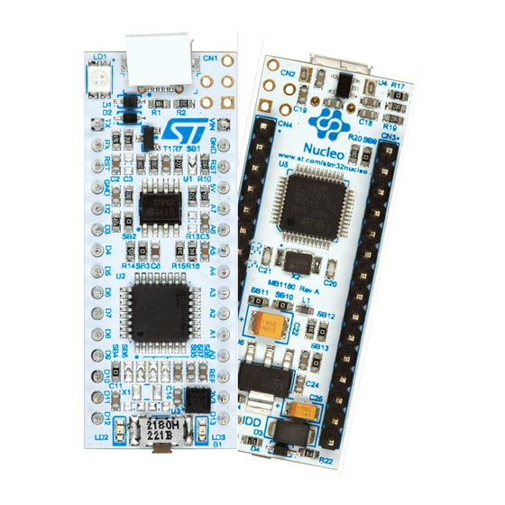
Figure 1. STM32 Nucleo-32 board
1. Picture not contractual
October 2015
DocID028406 Rev 1
1/31
www.st.com
1
Advertisement
Table of Contents


Need help?
Do you have a question about the STM32 NUCLEO-F042K6 and is the answer not in the manual?
Questions and answers