Table of Contents
Advertisement
Quick Links
UG-2023-01
EVAL-M1-IM523 user guide
iMotion™ modular application design kit
About this document
Scope and purpose
This user guide provides an overview of the evaluation board EVAL-M1-IM523 including its main features, key
data, pin assignments, and mechanical dimensions.
This evaluation board has been developed to provide initial support to customers in designing motor drive
applications for major home appliances such as air conditioners, pumps, fans, and other variable-speed drives.
The EVAL-M1-IM523 is part of the iMOTION™ modular application design kit (MADK). Together with a control
board equipped with the M1 20-pin interface connector, such as the EVAL-M1-101T, it features and
demonstrates the Infineon CIPOS™ Mini intelligent power module (IPM) technology and advanced motion
control engine (MCE 2.0) technology for permanent magnet motor drives. EVAL-M1-IM523 is based on the
IM523-X6A CIPOS™ Mini IPM. The IM523-X6A is designed to control 3-phase AC motors and permanent magnet
motors in variable-speed drives. It works with a voltage of 600 V and provides a current rating of 17 A.
Intended audience
This user guide is intended for all technical specialists who know motor control and low-power electronic
converters. The evaluation board is intended to be used under laboratory conditions.
Evaluation board
This evaluation board is to be used during the design-in process for evaluating and measuring characteristic
curves, and for checking datasheet specifications.
Note:
PCB and auxiliary circuits are NOT optimized for final customer design.
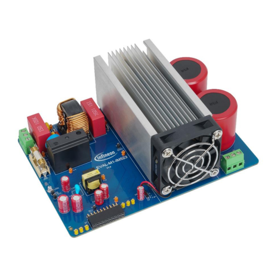
Figure 1
The iMotion
TM
MADK evaluation board for IM523-X6A CIPOS™ Mini IPM
Please read the Important Notice and Warnings at the end of this document
Revision 1.00
www.infineon.com
2023-01-16
Advertisement
Table of Contents

Subscribe to Our Youtube Channel
Related Manuals for Infineon iMotion EVAL-M1-IM523


Summary of Contents for Infineon iMotion EVAL-M1-IM523
-
Page 1: About This Document
M1 20-pin interface connector, such as the EVAL-M1-101T, it features and demonstrates the Infineon CIPOS™ Mini intelligent power module (IPM) technology and advanced motion control engine (MCE 2.0) technology for permanent magnet motor drives. EVAL-M1-IM523 is based on the IM523-X6A CIPOS™... - Page 2 Boards provided by Infineon Technologies. The design of the Evaluation Boards and Reference Boards has been tested by Infineon Technologies only as described in this document. The design is not qualified in terms of safety requirements, manufacturing and operation over the entire operating temperature range or lifetime.
-
Page 3: Safety Precautions
EVAL-M1-IM523 user guide iMotionTM modular application design kit Safety precautions Safety precautions Note: Please note the following warnings regarding the hazards associated with development systems. Table 1 Safety precautions Warning: The DC link potential of this board is up to 400 V . -
Page 4: Table Of Contents
EVAL-M1-IM523 user guide iMotionTM modular application design kit Table of contents Table of contents About this document ........................1 Safety precautions .......................... 3 Table of contents ..........................4 The board at a glance ......................5 Scope of supply ............................5 Block diagram ............................ -
Page 5: The Board At A Glance
The boards provided by Infineon are subjected to functional testing only. The evaluation boards are not subject to the same procedures as regular products regarding returned material analysis (RMA), process change notification (PCN), and product discontinuation (PD). -
Page 6: Main Features
EVAL-M1-IM523 user guide iMotionTM modular application design kit The board at a glance Figure 3 shows the functional groups of the EVAL-M1-IM523 board. Figure 3 The functional groups of the EVAL-M1-IM523 evaluation design Main features The EVAL-M1-IM523 evaluation board, combined in a kit with one of the available MADK control boards, has the following features: Input voltage 85 V to 255 V... -
Page 7: Board Parameters And Technical Data
EVAL-M1-IM523 user guide iMotionTM modular application design kit The board at a glance Board parameters and technical data Table 2 lists the important specifications of the EVAL-M1-IM523. Table 2 Parameters Parameter Symbol Conditions Value Unit Input Input voltage Lower AC input, less motor power output 85 - 255 Input current Input 220 V... -
Page 8: System And Functional Description
These tools can be downloaded from the Infineon website. Please check this page periodically for tool and software updates. An iMOTION™ link or an on-board USB-to-UART cable is needed to bridge the PC/debugger side and the motor drive system (on the target iMOTION™... - Page 9 EVAL-M1-IM523 user guide iMotionTM modular application design kit System and functional description Figure 5 MCEWizard’s welcome page After downloading and installing the MCEWizard and MCEDesigner, follow these steps to run the motor: Connect the EVAL-M1-101T control board to the EVAL-M1-IM523 evaluation board. Then, connect the PC- USB connector to the EVAL-M1-101T control board.
- Page 10 EVAL-M1-IM523 user guide iMotionTM modular application design kit System and functional description Figure 6 MCEWizard’s Verify & Save page Turn on the 220 V AC power supply, LED 1 and 2 turn red. Start the MCEDesigner tool and click File > Open to open the MCEDesigner default configuration file (.irc) for the IMC101T device (IMC101T_Vxxx.irc.) (The IMC101T_Vxxx.irc file is included in the downloaded IMC101T MCE software package).
- Page 11 EVAL-M1-IM523 user guide iMotionTM modular application design kit System and functional description In case of a blank IC: To program the firmware and the parameters file into the internal Flash memory of the iMOTION™ Control IC, follow these steps: a) Open the System Page. b) Click Tools >...
- Page 12 EVAL-M1-IM523 user guide iMotionTM modular application design kit System and functional description The VF Diagnostic sub-function can verify whether the: o Motor is correctly connected o IGBT/MOS and gate driver work as expected o Parameters related to current-sensing are correctly configured o PCB layout and DC bus decoupling have been done correctly After the VF Diagnostic is complete, click STOP (the red traffic light button) to stop the PWM (Pulse Width Modulation).
-
Page 13: Description Of Functional Blocks
EVAL-M1-IM523 user guide iMotionTM modular application design kit System and functional description Figure 10 Trace waveform for I & Flx-M at 50% speed To program a new parameter file after the firmware has been programmed, follow the instructions given in Step 9. - Page 14 EVAL-M1-IM523 user guide iMotionTM modular application design kit System and functional description A rugged SOI gate driver technology with stability against transient and negative voltage • An allowable negative V potential up to -11 V for signal transmission at V = 15 V •...
-
Page 15: System Design
To meet individual customer requirements, and to make the EVAL-M1-IM523 evaluation design a basis for development or modification, all board design data such as schematics, Gerber, and AD files can be found on Infineon’s website. EMI filter and soft power-up circuit Figure 12 shows the schematic from the AC input connector X1 to the rectified DC bus voltage. -
Page 16: Auxiliary Power Supply
Figure 14 shows the schematic of the auxiliary power supply for the EVAL-M1-IM523 board. The circuit includes the latest CoolSET 5 (ICE5GR4780AG) from Infineon and a flyback topology with direct output of 15 V and 6 V. The VCC is connected to the gate drivers inside the CIPOS™ IPM. -
Page 17: Layout
EVAL-M1-IM523 user guide iMotionTM modular application design kit System design Layout The EVAL-M1-IM523 board has two electrical layers with 140 µm copper (1 oz.) and a dimension of 160 mm x 115 mm. The thickness of the PCB board is 1.6 mm. Figure 15 and Figure 16 show the PCBA assembly of the EVAL- M1-IM523. -
Page 18: Bill Of Material
System design Bill of material The complete bill of material can be downloaded (a customer login is required) from the Download section on the homepage of Infineon’s website. Table 3 BOM of the most important/critical parts of the evaluation board... - Page 19 Leads, 4.50 mm L X 4 mm W X 3.50 mm H body / SMD / - LiteOn LED1 LED 3mm Red Through Hole Lamp LTL-1CHEE Optoelectronics Standard Heatsink Infineon Technologies HS-5050-100 M3 Metric Countersunk Head Screw, MP2, MP3, MP4 Duratool M310 KRSTMCZ100- Length 10mm MP5, MP6, MP7, Keystone Electronics Pan Head Screw, M3X0.5...
- Page 20 MP16 a self-adhesive rubber bumper PTC thermistor for overcurrent protection PTC1 TDK Corporation B59451C1130B070 and as inrush current limiters 30V 154mOhm@4.5V MOSFET Infineon Technologies IRLML2030TRPbF NPN Silicon Switching Transistor Infineon Technologies SMBT3904 R1, R2 Standard Thick Film Chip Resistor Vishay...
- Page 21 RELAY GENRAL PURPOSE SPST 20A Omron G4A-1A-PE 12VDC Flyback Transformer, Offline aux SMPS for Wurth Elektronik 750344226 server, PC power applications CIPOS Mini IM523 Infineon Technologies IM523-X6A Dual Comparators Texas Instruments LM393ADR 11MHz, Rail-to-Rail I/O CMOS Operational SGM721XN5/TR Amplifiers Low Dropout Linear Voltage Regulator, 5.0...
-
Page 22: System Performance
EVAL-M1-IM523 user guide iMotionTM modular application design kit System performance System performance Auxiliary power supply & inrush current test Table 4 Table 1 Auxiliary power supply voltage and inrush current test Specification 15 V: 15±0.5 V; 5 V: 5 V±5%; inrush current <10 A peak Condition Inrush tested at the 25℃... - Page 23 EVAL-M1-IM523 user guide iMotionTM modular application design kit System performance Figure 18 Auxiliary power supply browns out Figure 19 Input 85 V Figure 20 Input 220 V Revision 1.00 2023-01-16...
-
Page 24: Ripple
EVAL-M1-IM523 user guide iMotionTM modular application design kit System performance Figure 21 Input 255 V bus capacitors and V ripple Table 5 bus capacitors and V ripple Specification _Bus voltage ripple ratio is less than 10%. Condition Tested the V bus voltage ripple at the 220 V input and 5.5 A phase current. - Page 25 EVAL-M1-IM523 user guide iMotionTM modular application design kit System performance Figure 22 220 V input, V bus voltage ripple Figure 23 110 V input, V bus voltage ripple Revision 1.00 2023-01-16...
-
Page 26: Current Output Capability And Thermal Test
EVAL-M1-IM523 user guide iMotionTM modular application design kit System performance Current output capability and thermal test Table 6 Phase current and IPM case temperature at different PWM and load Specification PWM:4-20 kHz; IPM max. case temperature: about 100℃ ; input voltage range: 110~230 V ;... - Page 27 EVAL-M1-IM523 user guide iMotionTM modular application design kit System performance IPM ΔTc Vs. motor phase current at different PWM 4kHz 6kHz 10kHz 15kHz 20kHz 2.065 3.009 4.037 5.512 motor phase current (Arms) Figure 24 IPM ΔTc Vs. motor phase current at different PWM Figure 25 Iu &...
- Page 28 EVAL-M1-IM523 user guide iMotionTM modular application design kit System performance Figure 26 Iu & Flx_M at 15 kHz PWM, 220 V input, 900 W output (5.5 A phase current) Figure 27 Thermal test at 220 V input, 15 kHz PWM and 900 W output Revision 1.00 2023-01-16...
- Page 29 EVAL-M1-IM523 user guide iMotionTM modular application design kit System performance Figure 28 Scope waveform at 220 V input, 15 kHz PWM and 900 W output Figure 29 Figure 29 Scope waveform at 110 V input, 500 W output power, and 15 kHz PWM Revision 1.00 2023-01-16...
-
Page 30: Overvoltage & Undervoltage Protection
EVAL-M1-IM523 user guide iMotionTM modular application design kit System performance Overvoltage & undervoltage protection Table 7 Overvoltage & undervoltage protection Specification The overvoltage & undervoltage (OV/UV) protection threshold are set at OV=340 V(2697 counts); UV=100 V(793 counts). The system can be shut down when the DC bus voltage is over/under the threshold (±3 V);... - Page 31 EVAL-M1-IM523 user guide iMotionTM modular application design kit System performance UV protection Figure 31 Revision 1.00 2023-01-16...
-
Page 32: Over-Temperature Protection (Otp) Test
EVAL-M1-IM523 user guide iMotionTM modular application design kit System performance Over-temperature protection (OTP) test Table 8 Over-temperature Specification Over-temperaute threshold voltage is set at 3.4 V in MCEWizard and in the comparator on the board. The 3.4 V threshold value corresponds to 105±3℃ IPM case temperature. Data Operation Phenomenon... -
Page 33: Overcurrent Test
EVAL-M1-IM523 user guide iMotionTM modular application design kit System performance Overcurrent test Table 9 Overcurrent Specification Verify the software and hardware overcurrent protection (OCP) function. Data Operation Phenomenon Picture The motor stopped at 4.21 A phase current and peak Software OCP Figure 34 reported overcurrent fault in MCEDesigner fault flag. -
Page 34: Direct Current Feedback Test
EVAL-M1-IM523 user guide iMotionTM modular application design kit System performance Direct current feedback test Table 10 Direct current feedback test Specification Do not use the external amplifier on the board. The current feedback signal sends messages to the MCU AD input pin directly. Data Power source PWM (kHz) Input power (W) - Page 35 EVAL-M1-IM523 user guide iMotionTM modular application design kit System performance Figure 36 320 W load current feedback, 2 A phase current, 15 kHz PWM, 220 V input Figure 37 500 W load current feedback, 3 A phase current, 15 kHz PWM, 220 V input Figure 38 930 W load, 5.5 A...
- Page 36 EVAL-M1-IM523 user guide iMotionTM modular application design kit System performance Figure 39 Scope waveforms at 930 W load, 5.5 A phase current, 15 kHz PWM, 220 V input Figure 40 Flx_M & Iu waveform in MCEDesigner Revision 1.00 2023-01-16...
-
Page 37: Acronyms
EVAL-M1-IM523 user guide iMotionTM modular application design kit Acronyms Acronyms Table 11 Abbreviations Abbreviation Meaning Alternating current Altium designer Capacitance Continuous conduction mode Conformité Européenne CERA Ceramic Electromagnetic interference Electromagnetic compatibility Electrostatic discharge Electrical fast transient Direct current DCBUS Direct current bus voltage Discontinuous conduction mode Direct current bus voltage positive ELCO... - Page 38 EVAL-M1-IM523 user guide iMotionTM modular application design kit Acronyms Abbreviation Meaning Returned material analysis RoHS Restriction of hazardous substances in electrical and electronic equipment SGND Secondary ground Silicon-on-insulator UART Universal asynchronous receiver/transmitter Universal serial bus U phase/V phase/W phase Voltage circuit Revision 1.00 2023-01-16...
-
Page 39: References
[2] Infineon Technologies AG. Datasheet of Infineon IMC101T-F048_A-V1.03.03 www.infineon.com [3] Infineon Technologies AG. MCEWizard_V2.3.0.1 User Guide (2019) www.infineon.com [4] Infineon Technologies AG. MCEDesigner_V2.3.0.1 Application Guide (2019) www.infineon.com [5] Infineon Technologies AG. iMOTION™ Motion Control Engine Software Reference Manual (2020) V1.3 www.infineon.com Revision 1.00 2023-01-16... -
Page 40: Revision History
EVAL-M1-IM523 user guide iMotionTM modular application design kit Revision history Revision history Document Date Description of changes version V1.00 2023-01-16 User guide initial release Revision 1.00 2023-01-16... -
Page 41: Disclaimer
Due to technical requirements products may contain Published by dangerous substances. For information on the types Infineon Technologies AG in question please contact your nearest Infineon Technologies office. 81726 Munich, Germany Except as otherwise explicitly approved by Infineon Technologies in a written document signed by ©...
Need help?
Do you have a question about the iMotion EVAL-M1-IM523 and is the answer not in the manual?
Questions and answers