Table of Contents
Advertisement
Quick Links
UG-2021-01
EVAL-M1-IM241 user guide
iMOTION™ modular application design kit
About this document
Scope and purpose
This user guide provides an overview of the evaluation board EVAL-M1-IM241 including its main features, key
data, pin assignments and mechanical dimensions.
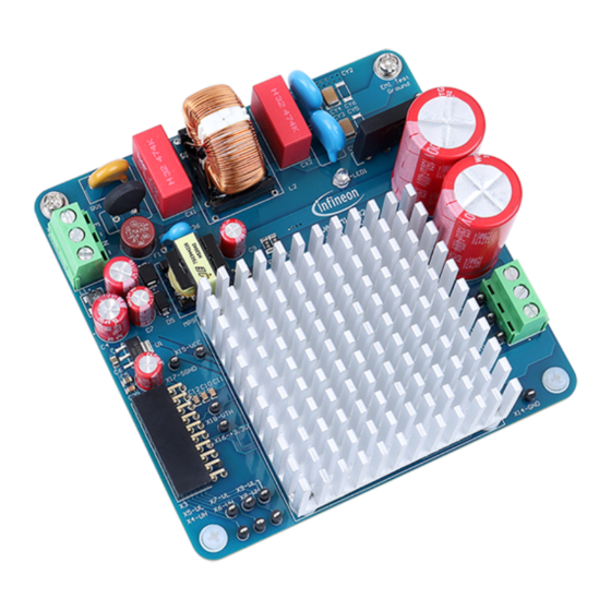
The EVAL-M1-IM241 is an evaluation board for motor drive applications, as part of the iMOTION™ modular
application design kit. In combination with the control board equipped with the M1 20-pin interface connector
such as EVAL-M1-101T, it features and demonstrates Infineon's CIPOS™ Micro IPM technology and advanced
motion control engine (MCE 2.0) technology for permanent magnet motors drive.
The IM241-L6T2B CIPOS™ Micro IPM has 600 V of voltage and 6 A of current rating. It is optimized for small home
appliances like pumps, fans and other low power motor drive applications.
This evaluation board EVAL-M1-IM241 is developed to support customers during their first steps designing
applications with CIPOS™ Micro IPM IM241-L6T2B and running any permanent magnet motor via sensorless
sinusoidal control.
Intended audience
This user guide is intended for all technical specialists who know motor control, low-power electronics
converters. The board is intended to be used under laboratory conditions.
Evaluation Board
This board will be used during design in, for evaluation and measurement of characteristics, and proof of data
sheet specifications.
Note:
PCB and auxiliary circuits are not optimized for final customer design.
User guide
Please read the Important notice and the Safety precautions and the Warnings
V0.1
www.infineon.com
page 1 of 38
2021-03-19
Advertisement
Table of Contents

Subscribe to Our Youtube Channel
Related Manuals for Infineon EVAL-M1-IM241


Summary of Contents for Infineon EVAL-M1-IM241
-
Page 1: About This Document
About this document Scope and purpose This user guide provides an overview of the evaluation board EVAL-M1-IM241 including its main features, key data, pin assignments and mechanical dimensions. The EVAL-M1-IM241 is an evaluation board for motor drive applications, as part of the iMOTION™ modular application design kit. -
Page 2: Important Notice
Boards provided by Infineon Technologies. The design of the Evaluation Boards and Reference Boards has been tested by Infineon Technologies only as described in this document. The design is not qualified in terms of safety requirements, manufacturing and operation over the entire operating temperature range or lifetime. -
Page 3: Safety Precautions
· EVAL-M1-IM241 user guide iMOTION™ modular application design kit Safety precautions Safety precautions Note: Please note the following warnings regarding the hazards associated with development systems. Table 1 Safety precautions Warning: The DC link potential of this board is up to 400 VDC. When measuring voltage waveforms by oscilloscope, high voltage differential probes must be used. -
Page 4: Table Of Contents
Block diagram ............................5 Main features ............................6 Board parameters and technical data ....................6 System and functional description ................... 9 Getting started with EVAL-M1-IM241 ...................... 9 Description of the functional blocks ..................... 15 2.2.1 Overview of IM241-L6T2B ........................ 15 2.2.2... -
Page 5: The Board At A Glance
The board at a glance The board at a glance The EVAL-M1-IM241 evaluation power board is a part of the iMOTION™ modular application design kit for motor drives (iMOTION™ MADK). The MADK platform is intended for use with various power stages and different control boards. -
Page 6: Main Features
Functional groups of the EVAL-M1-IM241 reference design Main features The EVAL-M1-IM241 is an evaluation board for motor drive applications. Combined in a kit with one of the available MADK control board options, it demonstrates Infineon’s motion control IC and IPM technology for motor drives. - Page 7 EVAL-M1-IM241 user guide iMOTION™ modular application design kit The board at a glance Table 2 Parameter Parameter Symbol Conditions Value Unit Input Input voltage Lower AC input, less motor 110 ~ 230 power output Input current Input 220 V =6 kHz, AC(max1) =25°C, T...
- Page 8 EVAL-M1-IM241 user guide iMOTION™ modular application design kit The board at a glance Parameter Symbol Conditions Value Unit Material FR4, 1.6 mm thickness, 2 oz. System environment Ambient °C temperature User guide 8 of 38 V0.1 2021-03-19...
-
Page 9: System And Functional Description
System and functional description Getting started with EVAL-M1-IM241 In order to run the motor system, a combination of the iMOTION™ MADK power board (EVAL-M1-IM241) and the matching MADK control board (EVAL-M1-101T or other control board) are required. This chapter provides more details on setting up the system and getting started with the iMOTION™... - Page 10 EVAL-M1-IM241 user guide iMOTION™ modular application design kit System and functional description Figure 3 shows the basic system connection using EVAL-M1-IM241 to run a 400 W GK6040-6AC31-WEZ1 motor with MCEDesigner. EMI test ground AC input Control board UVW phase output...
- Page 11 MCEDesigner user interface Here are the steps needed to run the motor: 1. Connect EVAL-M1-101T control board to EVAL-M1-IM241, and connect PC-USB connector to EVAL-M1-101T. 2. Connect 220 V AC power supply and UVW outputs to the motor. 3. Use MCEWizard to enter the target motor’s system and operating parameters, as well as evaluation board’s hardware parameters, which will then be used to calculate the digital parameter set of the controller representing the complete motor drive system.
- Page 12 EVAL-M1-IM241 user guide iMOTION™ modular application design kit System and functional description MCEWizard Verify and Save page Figure 6 5. Turn on 220 V AC power supply, red LED1 & LED2 ON. 6. Start MCEDesigner tool and open MCEDesigner default configuration file (.irc) for IMC101T device (IMC101T_Vxxx.irc) by clicking “File”...
- Page 13 EVAL-M1-IM241 user guide iMOTION™ modular application design kit System and functional description (If blank IMC101T IC, MCE Designer will pop up information “Target device firmware and parameter files are not programmed!”) Program the MCE firmware and system parameters into the internal Flash memory of iMOTION™...
- Page 14 EVAL-M1-IM241 user guide iMOTION™ modular application design kit System and functional description Trace waveform for Iu & Iv open loop diagnostic Figure 9 11. Start the motor by clicking the green traffic light button in the control bar (or double-click Start Motor sub function in Motor1 page, group of User Application Function Definitions);...
-
Page 15: Description Of The Functional Blocks
For detailed information on controller programming, refer to AN2018-33 iMOTION™ 2.0 Device Programming, MCEDesigner documentation and MCEWizard documentation. Description of the functional blocks The motor inverter of EVAL-M1-IM241 reference design is implemented by the IM241 module, and the auxiliary power supply is based on fixed frequency CoolSET ICE5GR4780AG. -
Page 16: Overview Of Ice5Gr4780Ag
Figure 11 IM241 internal block 2.2.2 Overview of ICE5GR4780AG The ICE5GR4780AG is Infineon’s latest 5 generation fixed frequency CoolSET offers high performance and integration of latest generation of 800 V CoolMOS P7 super-junction MOSFETs in DSO-12 package. Figure 12 illustrates the internal block diagram and typical isolated flyback application. -
Page 17: Motor External Current Feedback Configuration And Calculation
EVAL-M1-IM241 user guide iMOTION™ modular application design kit System and functional description Main features of ICE5GR4780AG include: Integrated 700 V/ 800 V avalanche rugged CoolMOS Enhanced Active Burst Mode with selectable entry and exit standby power Digital frequency reduction for better overall system efficiency ... - Page 18 ��ℎ ���� ��ℎ ��ℎ �� �������������� ���������� = �� �� �� + �� ��ℎ ��ℎ Based on this calculation, the current input for the MADK combination of EVAL-M1-101T and EVAL-M1-IM241 is 83.3 mV/A. User guide 18 of 38 V0.1 2021-03-19...
-
Page 19: System Design
System design System design The EVAL-M1-IM241 board is an optimized design for 220 V small home appliances like fan applications. To meet individual customer requirements and to make the EVAL-M1-IM241 reference design a basis for development or modification, all board design data such as schematics, Gerber and AD files can be found on the Infineon homepage. - Page 20 EVAL-M1-IM241 user guide iMOTION™ modular application design kit System design R29 1MEG Power X18-VTH +3.3V SGND X10-U Half-Bridge HVIC 1 U/VS1 VDD1 PWMUH HIN1 PWMUL X11-V LIN1 Half-Bridge HVIC 2 V/VS2 VDD2 PWMVH HIN2 PWMVL X12-W LIN2 Half-Bridge HVIC 3...
-
Page 21: Layout
This board has two electrical layers with 140 µm copper (2 oz. copper) and dimensions of 100 mm × 100 mm. The thickness of the PCB board is 1.6 mm. Figure 17 illustrates the top assembly print of the reference design. Figure 17 Top assembly print of the EVAL-M1-IM241 User guide 21 of 38 V0.1... - Page 22 EVAL-M1-IM241 user guide iMOTION™ modular application design kit System design Figure 18 depicts the bottom assembly print of the evaluation board. Figure 18 Bottom assembly print of the EVAL-M1-IM241 User guide 22 of 38 V0.1 2021-03-19...
- Page 23 EVAL-M1-IM241 user guide iMOTION™ modular application design kit System design The top layer of the PCB is provided in Figure 19. Figure 19 Top layer of the EVAL-M1-IM241 User guide 23 of 38 V0.1 2021-03-19...
-
Page 24: Bill Of Material
Figure 20 Bottom layer of the EVAL-M1-IM241 Bill of material The complete bill of material is available on the download section of the Infineon homepage. A log-in is required to download this material. Table 3 BOM of the most important/critical parts of the evaluation S. -
Page 25: Connector Details
Yunlu Energy Common choke 0324510376A Technology Connector details General information about the connectors of the EVAL-M1-IM241 reference design is provided in this section. Table 4 includes the details of the AC input connector. Table 4 AC input connector (X1) Label... -
Page 26: Test Points
EVAL-M1-IM241 user guide iMOTION™ modular application design kit System design Name Pin name connectors +3.3 V On board 3.3 V supply PWMWH 3.3 V compatible logic input for high side gate driver-Phase W Positive current sense output PWMWL 3.3 V compatible logic input for low side gate driver-Phase W... -
Page 27: System Performance
The final case-to-ambient resistance value is roughly: ��ℎ���� Test results for output ability In order to test the total output power capability of EVAL-M1-IM241 design, the IPM case temperature is tested with different MADK input power and motor output current. The test conditions are: Ambient temperature T =25℃... - Page 28 EVAL-M1-IM241 user guide iMOTION™ modular application design kit System performance The module case temperature vs output power is shown as Figure 22. R is based on the existing heatsink on thCA the evaluation board and without fan cooling. Case temperature vs output power...
-
Page 29: Test Results For Pwm Range
EVAL-M1-IM241 user guide iMOTION™ modular application design kit System performance Test results for PWM range Figure 23 shows the output ability at different PWM frequencies, which are performed under the following conditions: 6~20 kHz PWM, three-phase modulation The case temperature of IM241-L6T2B reaches 100℃... -
Page 30: Overcurrent Protection
EVAL-M1-IM241 user guide iMOTION™ modular application design kit System performance Overcurrent protection Figure 24 displays the overcurrent protection circuitry. The current sensing signal I_Shunt is connected to gatekill (GK) via the comparator U6A. If the motor peak current is larger than the setting value I for more than input filter time, the RFE will be triggered low, which means that the GK signal is active. -
Page 31: Short Circuit Protection
EVAL-M1-IM241 user guide iMOTION™ modular application design kit System performance The signal response of this overcurrent protection circuit is shown in Figure 26. CH2: ITRIP CH3: U phase output current CH4: GK Figure 26 Overcurrent protection response waveform Short circuit protection Figure 27 displays the short circuit protection circuitry. - Page 32 EVAL-M1-IM241 user guide iMOTION™ modular application design kit System performance Figure 28 ITRIP time waveform Please refer to Figure 29,Figure 30 and Figure 31 for actual test waveforms. The test results are as follows: =850 ns =1.44 µs ...
- Page 33 EVAL-M1-IM241 user guide iMOTION™ modular application design kit System performance CH1: Short circuit current (20 mV/A) CH2: ITRIP CH3: U phase CH4: RFE Figure 30 waveform ITRIP CH1: Short circuit current (20 mV/A) CH2: ITRIP CH3: U phase CH4: RFE...
-
Page 34: Emi Test Results
EVAL-M1-IM241 user guide iMOTION™ modular application design kit System performance EMI test results Figure 32, Figure 33 and Figure 34 shows the EMI performance at different load, which are performed under the following conditions: 10 kHz PWM, three-phase modulation ... - Page 35 EVAL-M1-IM241 user guide iMOTION™ modular application design kit System performance 100% load CISPR_QP CISPR_AV Line PK EN 55032 Line AV Mark 120.0 162.0 KHz 438.0 KHz 19.736 MHz 50.287 53.246 55.493 438.0 KHz 500.0 KHz 5.0 MHz 5.001 MHz 18.284 MHz AV_Mark 106.0...
-
Page 36: References And Appendices
[4] Infineon Technologies AG. MCEDesigner_V2.3.0.0 Application Guide (2019) www.infineon.com [5] Infineon Technologies AG. iMOTION™ Motion Control Engine Software Reference Manual (2020) V1.3 www.infineon.com Ordering details and other information The power board is now available for customers in small order quantities. In order to initiate the testing,... -
Page 37: Revision History
EVAL-M1-IM241 user guide iMOTION™ modular application design kit Revision history Revision history Document Date of release Description of changes version V0.1 2021-03-12 First draft User guide 37 of 38 V0.1 2021-03-19... - Page 38 WARNINGS 81726 Munich, Germany Due to technical requirements products may contain dangerous substances. For information on the types in question please contact your nearest Infineon © 2021 Infineon Technologies AG. Technologies office. All Rights Reserved. Except as otherwise explicitly approved by Infineon...
Need help?
Do you have a question about the EVAL-M1-IM241 and is the answer not in the manual?
Questions and answers