Table of Contents
Advertisement
Quick Links
UG2020-29
EVAL-M1-IM535 user guide
iMOTION™ modular application design kit
About this document
Scope and purpose
This user guide provides an overview of the evaluation board EVAL-M1-IM535 including its main features, key
data, pin assignments and mechanical dimensions.
The EVAL-M1-IM535 is an evaluation board for motor drive applications, as part of the iMOTION™ modular
application design kit. In combination with the control board equipped with the M1 20-pin interface connector
such as EVAL-M1-101T, it features and demonstrates Infineon's CIPOS™ Mini IPM technology and advanced
motion control engine (MCE 2.0) technology for permanent magnet motors drive.
The IM535-U6D CIPOS™ Mini IPM has 600 V of voltage and 30 A of current rating. It is optimized for major home
appliances like air conditioners, pumps, fans and other low & middle power motor drive applications.
This evaluation board EVAL-M1-IM535 is developed to support customers during their first steps designing
applications with CIPOS™ Mini IPM IM535-U6D and running any permanent magnet motor via sensorless
sinusoidal control.
Intended audience
This user guide is intended for all technical specialists who know motor control, middle- and low-power
electronics converters. The board is intended to be used under laboratory conditions.
Evaluation Board
This board will be used during design-in, for evaluation and measurement of characteristics, and proof of data
sheet specifications.
Note:
PCB and auxiliary circuits are NOT optimized for final customer design.
Please read the Important notice and the Safety precautions and the Warnings
V1.0
www.infineon.com
page 1 of 39
2020-09-30
Advertisement
Table of Contents

Subscribe to Our Youtube Channel
Related Manuals for Infineon iMOTION EVAL-M1-IM535


Summary of Contents for Infineon iMOTION EVAL-M1-IM535
-
Page 1: About This Document
In combination with the control board equipped with the M1 20-pin interface connector such as EVAL-M1-101T, it features and demonstrates Infineon’s CIPOS™ Mini IPM technology and advanced motion control engine (MCE 2.0) technology for permanent magnet motors drive. -
Page 2: Important Notice
Boards provided by Infineon Technologies. The design of the Evaluation Boards and Reference Boards has been tested by Infineon Technologies only as described in this document. The design is not qualified in terms of safety requirements, manufacturing and operation over the entire operating temperature range or lifetime. -
Page 3: Safety Precautions
EVAL-M1-IM535 user guide iMOTION™ modular application design kit Safety precautions Safety precautions Note: Please note the following warnings regarding the hazards associated with development systems. Table 1 Safety precautions Warning: The DC link potential of this board is up to 400 V . -
Page 4: Table Of Contents
EVAL-M1-IM535 user guide iMOTION™ modular application design kit Table of contents Table of contents About this document ........................1 Important notice ..........................2 Safety precautions .......................... 3 Table of contents ..........................4 The board at a glance ......................5 Delivery content ............................5 Block diagram ............................ -
Page 5: The Board At A Glance
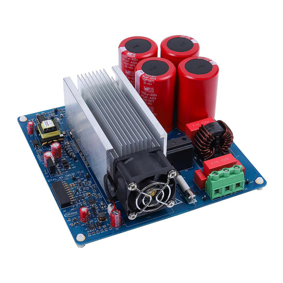
The EVAL-M1-IM535 evaluation board is available through regular Infineon distribution partners as well as on Infineon's website. The features of this board are described in the main features chapter of this document, whereas the remaining paragraphs provide information to enable the customers to copy, modify and qualify the design for production according to their own specific requirements. - Page 6 EVAL-M1-IM535 user guide iMOTION™ modular application design kit The board at a glance Figure 2 points out the functional groups on the top side of the EVAL-M1-IM535 design: 1. 220 V & PE input connector 8. iMOTION MADK M1 connector (20-pin) 2.
-
Page 7: Main Features
Main features The EVAL-M1-IM535 is an evaluation board for motor drive applications. Combined in a kit with one of the available MADK control board options, it demonstrates Infineon’s motion control IC and IPM technology for motor drives. The evaluation board characteristics include: •... - Page 8 EVAL-M1-IM535 user guide iMOTION™ modular application design kit The board at a glance Parameter Symbol Conditions / comments Value Unit Motor current Hardware comparator overcurrent protection, trip peak protection trigger level related to shunt resistor and LM393 setup Thermal protection Temperature gap between junction and NTC °...
-
Page 9: System And Functional Description
The iMOTION™ software tools, MCEDesigner and MCEWizard, are required to initially set up the system, as well as to control and fine-tune the system performance to match the user’s exact needs. These tools are available for download via the Infineon website (https://www.infineon.com/cms/en/product/power/motor-control- ics/digital-motor-controller-imotion/imc101t-t038/#!tools ). - Page 10 EVAL-M1-IM535 user guide iMOTION™ modular application design kit System and functional description Motor phase outputs To EVAL-M1-101T (controller board) Power Input Figure 3 System connection example MCEWizard welcome page Figure 4 10 of 39 V1.0 2020-09-30...
- Page 11 EVAL-M1-IM535 user guide iMOTION™ modular application design kit System and functional description Figure 5 MCEDesigner user interface Here are the steps needed to run the motor: 1. Connect EVAL-M1-101T control board to EVAL-M1-IM535, and connect PC-USB connector to EVAL-M1-101T. 2. Connect 220 V AC power supply and UVW outputs to the motor. 3.
- Page 12 EVAL-M1-IM535 user guide iMOTION™ modular application design kit System and functional description MCEWizard Verify and Save page Figure 6 5. Turn on 220 V AC power supply, red LED1 & LED2 ON. 6. Start MCEDesigner tool and open MCEDesigner default configuration file (.irc) for IMC101T device (IMC101T_Vxxx.irc) by clicking “File”...
- Page 13 EVAL-M1-IM535 user guide iMOTION™ modular application design kit System and functional description 9. In case of blank IC: Take the following steps to program the firmware and the parameters file into the internal Flash memory of iMOTION™ Control IC: Click on system page, click “Tools” > “Programmer” and select “Program Firmware and Parameters,”...
- Page 14 EVAL-M1-IM535 user guide iMOTION™ modular application design kit System and functional description Trace waveform for Iu & Iv open loop diagnostic Figure 9 11. Start the motor by clicking the green traffic light button in the control bar (or double-click Start Motor sub function in Motor1 page, group of User Application Function Definitions);...
- Page 15 EVAL-M1-IM535 user guide iMOTION™ modular application design kit System and functional description Trace waveform for Iu & Flx-M at 50% speed Figure 10 14. Once the firmware has been programmed, in case a new parameter file has to be programmed, follow the same instructions given in step 9.
-
Page 16: Description Of The Functional Blocks
EVAL-M1-IM535 user guide iMOTION™ modular application design kit System and functional description Description of the functional blocks The motor inverter of EVAL-M1-IM535 reference design is implemented by the IM535 module, and the auxiliary power supply is based on fixed frequency CoolSET ICE5AR4770BZS. -
Page 17: Overview Of Ice5Ar4770Bzs
System and functional description 2.2.2 Overview of ICE5AR4770BZS The ICE5AR4770BZS is Infineon’s latest 5 generation fixed frequency CoolSET , offers high performance and integration of latest generation of 700 V CoolMOS superjunction MOSFETs in DIP-7 package. -
Page 18: Motor Current Sensing Op-Amp Configuration And Calculation
EVAL-M1-IM535 user guide iMOTION™ modular application design kit System and functional description 2.2.3 Motor current sensing op-amp configuration and calculation In order to suppress common mode noise between this power board and the MADK control board, an 11 MHz rail-to rail I/O CMOS OPA SGM721XN5 is used for motor current sensing. Two 5 mΩ... - Page 19 EVAL-M1-IM535 user guide iMOTION™ modular application design kit System and functional description R30 and R31 build the input differential mode LPF, which can damp parts of PWM switching noise. The default LPF time constants is 2*RC = 2*(R28//R29)*C29 = 470 ns. The typical setup time is 0.1~0.5 µs, which depends on PCB layout, DC bus decouple capacitor and IGBT / MOS gate driver configuration.
-
Page 20: System Design
To meet individual customer requirements and to make the EVAL-M1-IM535 reference design a basis for development or modification, all board design data such as schematics, Gerber and Altium design data can be found on the Infineon homepage. Schematics The overall schematic diagram for EVAL-M1-IM535 are provided in Figure 16 and Figure 17. - Page 21 EVAL-M1-IM535 user guide iMOTION™ modular application design kit System design PC817 used for primary isolation of flyback power supply, is not for real isolation, but for easier PCB layout for signal ground and power ground connections. This can reduce common-mode noise for controller board, and achieve higher SNR for motor current sensing.
- Page 22 EVAL-M1-IM535 user guide iMOTION™ modular application design kit System design Figure 17 Schematics for IM535 IPM and peripheral circuit 22 of 39 V1.0 2020-09-30...
-
Page 23: Layout
EVAL-M1-IM535 user guide iMOTION™ modular application design kit System design Layout This board has two electrical layers with 70 µm copper (2 oz. copper) and dimensions of 166 mm × 166 mm. The thickness of the PCB board is 1.6 mm. Figure 18 illustrates the top assembly print of the reference design. Top assembly print of the EVAL-M1-IM535 reference design Figure 18 23 of 39... - Page 24 EVAL-M1-IM535 user guide iMOTION™ modular application design kit System design The top layer and bottom layer routing of the PCB are provided in Figure 19 and Figure 20. Top layer routing of the EVAL-M1-IM535 Figure 19 Figure 20 Bottom layer routing of the EVAL-M1-IM535 24 of 39 V1.0 2020-09-30...
-
Page 25: Bill Of Material
System design Bill of material Table 3 shows the major parts of EVAL-M1-IM535 design. The complete bill of material is available on the download section of the Infineon homepage. A log-in is required to download this material. Table 3 BOM of the most important/critical parts of the evaluation or reference board S. -
Page 26: Connector Details
EVAL-M1-IM535 user guide iMOTION™ modular application design kit System design Connector details General information about the connectors of the EVAL-M1-IM535 reference design is provided in this section. Table 4 includes the details of the AC input connector. Table 4 AC input connector (J4) Label Function AC line... -
Page 27: Test Points
EVAL-M1-IM535 user guide iMOTION™ modular application design kit System design Name Pin name connectors Positive current sense output PWMWL 5 V compatible logic input for low side gate driver-Phase W I_U- Negative current sense output or ground Gatekill signal – active low when overcurrent is detected DCBSense DC bus positive voltage, scaled in 0-5 V range by a voltage divider Thermistor output... -
Page 28: System Performance
EVAL-M1-IM535 user guide iMOTION™ modular application design kit System performance System performance Heatsink thermal resistance test result In order to test the thermal impedance of heatsink to ambient R , the DC source is used to conduct the IPM thCA internal diodes, as shown in Figure 21. -
Page 29: Test Results For Output Ability
EVAL-M1-IM535 user guide iMOTION™ modular application design kit System performance Therefore, the final case-to-ambient resistance value is roughly: �� = 2.4 ℃/�� ��ℎ���� Please note that: • 2.4 ℃/�� thermal resistance is calculated with a fan voltage of 10 V. •... - Page 30 EVAL-M1-IM535 user guide iMOTION™ modular application design kit System performance Input Power Vs Delta T Input Power (W) 1000 1500 2000 2500 3000 3500 Output current Vs Delta T Motor current (A) Figure 24 EVAL-M1-IM535 output power capability test result 30 of 39 V1.0 2020-09-30...
-
Page 31: Test Results For Pwm Range
EVAL-M1-IM535 user guide iMOTION™ modular application design kit System performance Test results for PWM range Figure 25 shows the output ability at different PWM frequencies, which are performed under the following conditions: 4~20 kHz PWM, three-phase modulation Run GK6081 motor at 1000RPM (about 40% V modulation) and increase motor load at given PWM ... -
Page 32: Test Results For Overcurrent Protection
EVAL-M1-IM535 user guide iMOTION™ modular application design kit System performance Test results for overcurrent protection The IM535 product family provides an overcurrent detection function by connecting the ITRIP input with the IGBT current feedback, and IGBT short-circuit withstand time is 5 µs. Overcurrent detection generates a shutdown of outputs of the gate driver if ITRIP pin input is over 525 mV and lasts longer than 300ns. - Page 33 EVAL-M1-IM535 user guide iMOTION™ modular application design kit System performance Figure 27 Overcurrent protection response waveform (CH1: IFB+, CH2: VFO, CH3: Itrip) 33 of 39 V1.0 2020-09-30...
-
Page 34: Test Results For Over-Temperature Protection
EVAL-M1-IM535 user guide iMOTION™ modular application design kit System performance Test results for over-temperature protection The IM535 IPM has an internal NTC resistor, which connects to VFO multifunction pin, as shown in Figure 28: Figure 28 Temperature sensing for IM535-U6D The IM535-U6D IPM built-in NTC thermistor is 85 kOhm at 25℃... - Page 35 EVAL-M1-IM535 user guide iMOTION™ modular application design kit System performance VFO Output 4400 4200 4000 3800 3600 3400 3200 IPM Case Temperature (℃) 3000 OTP (NTC circuit) and output voltage curve Figure 29 Please note that output of VFO pin is very noisy; EVAL-M1-101T’s OTP function might be triggered by noise. Normally the MCEWizard setup needs to consider a margin for the input noise, for example, setup 3.3 ~ 3.4 V in MCEWizard corresponding to the real shutdown temperature of 110 ~ 120°...
-
Page 36: Test Result For Dc Bus Voltage Ripple
EVAL-M1-IM535 user guide iMOTION™ modular application design kit System performance Test result for DC bus voltage ripple The EVAL-M1-IM535 design does not equip PFC function, which means the DC bus voltage is determined by the AC input voltage and the load of motor; the DC bus voltage ripple is the function of IPM inverter load and grid input. -
Page 37: References And Appendices
Conformité Européenne Electromagnetic interference Underwriters Laboratories Operational amplifier Low-pass filter References Datasheet of Infineon IM535-U6D Datasheet of Infineon IMC101T MCEWizard User Guide MCEDesigner User Guide Infineon-MCESW-RM-User Manual Ordering details and other information The power board is now available for customers in small order quantities. In order to initiate the testing,... -
Page 38: Revision History
EVAL-M1-IM535 user guide iMOTION™ modular application design kit Revision history Revision history Document Date of release Description of changes version V1.0 2020-9-30 First release 38 of 39 V1.0 2020-09-30... - Page 39 WARNINGS 81726 Munich, Germany Due to technical requirements products may contain dangerous substances. For information on the types in question please contact your nearest Infineon © 2020 Infineon Technologies AG. Technologies office. All Rights Reserved. Except as otherwise explicitly approved by Infineon...
Need help?
Do you have a question about the iMOTION EVAL-M1-IM535 and is the answer not in the manual?
Questions and answers