Table of Contents
Advertisement
Quick Links
AN2017-10 EVAl-M1-05F804 User Manual
EVAL-M1-05F804 User Manual
iMOTION™ Modular Application Design Kit
About this document
Scope and purpose
This application note provides an overview of the evaluation board EVAL-M1-05F804 including its main features,
key data, pin assignments and mechanical dimensions.
EVAL-M1-05F804 is a complete power evaluation board including three CIPOS™ Nano 40V half-bridge modules
for motor drive application. In combination with either EVAL-M1-101T or EVAL-M1-099M it features and
demonstrates Infineon's CIPOS™ technology for motor drive.
The evaluation board EVAL-M1-05F804 was developed to support customers during their first steps designing
applications with IRSM005-800MH CIPOS™ Nano power modules.
Intended audience
This application note is intended for all technical specialists working with the EVAL-M1-05F804 board.
Table of Contents
About this document ....................................................................................................................... 1
Table of Contents ........................................................................................................................... 1
1
Safety precautions ......................................................................................................... 2
2
Introduction .................................................................................................................. 4
3
Main features ................................................................................................................ 5
3.1
Key data ................................................................................................................................................... 6
4
Pin assignments ........................................................................................................... 10
5
Getting Started with EVAL-M1-05F804 ............................................................................. 11
5.1
Setting up the system............................................................................................................................ 11
5.2
iMOTION™ development tools and software ....................................................................................... 13
5.2.1
MCEWizard setup overview .............................................................................................................. 13
5.2.2
MCEDesigner setup overview .......................................................................................................... 15
6
Schematics and Layout .................................................................................................. 17
6.1
DC-Link Voltage Measurement ............................................................................................................. 17
6.2
Inverter section using CIPOS™ Nano .................................................................................................... 18
6.3
Power supply ......................................................................................................................................... 20
6.4
Over current protection circuitry .......................................................................................................... 20
6.5
PCB Layout ............................................................................................................................................ 21
7
Bill of Materials of EVAL-M1-05F804 ................................................................................ 23
8
Reference .................................................................................................................... 25
Revision History ............................................................................................................................ 26
User Manual
www.infineon.com
Please read the Important Notice and Warnings at the end of this document
<Revision 1.1>
<2018-07-09>
Advertisement
Table of Contents

Related Manuals for Infineon EVAL-M1-05F804


Summary of Contents for Infineon EVAL-M1-05F804
-
Page 1: Table Of Contents
About this document Scope and purpose This application note provides an overview of the evaluation board EVAL-M1-05F804 including its main features, key data, pin assignments and mechanical dimensions. EVAL-M1-05F804 is a complete power evaluation board including three CIPOS™ Nano 40V half-bridge modules for motor drive application. -
Page 2: Safety Precautions
Table 1 Precautions Attention: The ground potential of the EVAL-M1-05F804 system is biased to a negative DC bus voltage potential. When measuring voltage waveform by oscilloscope, the scope’s ground needs to be isolated. Failure to do so may result in personal injury or death. - Page 3 Failure to do so may result in personal injury or death. Attention: EVAL-M1-05F804 system is shipped with packing materials that need to be Removed prior to installation. Failure to remove all packing materials which are unnecessary for system installation may result in overheating or abnormal operating condition.
-
Page 4: Introduction
DC input and 3-phase output for power. It contains three emitter-shunts for current sensing and a voltage divider for DC-link voltage measurement. The EVAL-M1-05F804 evaluation board is available from Infineon. The features of this board are described in the design feature chapter of this document, whereas the remaining paragraphs provide information to enable the customers to copy, modify and qualify the design for production according to their own specific requirements. -
Page 5: Main Features
Main features Main features EVAL-M1-05F804is a complete power evaluation board including a 3-phase IPM for motor drive application. The kit demonstrates Infineon’s IPM technology for motor drives. Main features of CIPOS™ Nano Intelligent Power Module IRSM005-800MH are: • MOSFET Drain-to-Source Voltage 40V •... -
Page 6: Key Data
EVAL-M1-05F804 User Manual iMOTION™ Modular Application Design Kit Main features Key data Figure 2 provides the overview of the IRSM005-800MH internal electrical schematics. For further information regarding these CIPOS™ like static and dynamic electrical behavior, as well as thermal and mechanical characteristics please refer to the datasheet of the IRSM005-800MH. - Page 7 Logic input Voltage LIN, HIN High side PWM pulse width μs Dead time Suggested dead time between LIN and HIN μs Table 4 shows the important specifications of the evaluation board EVAL-M1-05F804. Table 4 Eval-M1-05F804 board specifications Parameters Values Conditions / comments...
- Page 8 EVAL-M1-05F804 User Manual iMOTION™ Modular Application Design Kit Main features Parameters Values Conditions / comments Dimension 118mmx85mm System environment Ambient temperature 0-70°C 95%RH Max (Non-Condensing) Note 2: please refer to IRSM005-800MH datasheet for data about maximum current and power, changing Fc, modulation, ∆Tca, use of a heat sink.
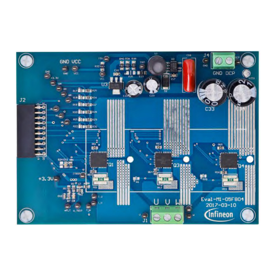
- Page 9 EVAL-M1-05F804 User Manual iMOTION™ Modular Application Design Kit Main features Figure 3 and Figure 4 hint out the functional groups of the EVAL-M1-05F804 evaluation board. 1. DC Line connector (J4) 2.On board power supply for 15 V and 3.3 V generations 3.
-
Page 10: Pin Assignments
Modular Application Design Kit Pin assignments Pin assignments General information about the connectors of the EVAL-M1-05F804 evaluation board is reported. Table 5 Include the details of the DC input connector J4-DC. Table 6 denotes the details of the motor side connector J1. -
Page 11: Getting Started With Eval-M1-05F804
Getting Started with EVAL-M1-05F804 Getting Started with EVAL-M1-05F804 In order to run the motor system, a combination of the iMOTION™ MADK power board EVAL-M1-05F804 and the matching MADK control board (with M1 connector, EVAL-M1-101T for example in this chapter) is required. The iMOTION™... - Page 12 EVAL-M1-05F804 User Manual iMOTION™ Modular Application Design Kit Getting Started with EVAL-M1-05F804 7. Start MCEDesigner tool and open MCEDesigner default configuration file (.irc) for IMC101T-T038 controller (IMC101T_Vxxx.irc) by clicking “File” > “Open”. IMC101T_Vxxx.irc file is included in ”IMC101T-T038 MCE Software Package” downloaded in step 1.
-
Page 13: Imotion™ Development Tools And Software
“Welcome Page” for MCEWizard, where the MADK control board or power board can be selected through the pull-down list. Infineon keeps releasing new MADK controller and power boards. Therefore, it could happen that some of the newest power boards are not pre-configured in the MCEWizard tool and cannot be selected through the pull-down menu. - Page 14 EVAL-M1-05F804 User Manual iMOTION™ Modular Application Design Kit Getting Started with EVAL-M1-05F804 Table 8 provides the MCEWizard setup overview for hardware related parameters. Similar tables will be available in each power board’s Application Note. Combination of this table and the corresponding table of the power board provides enough information to setup the MADK-based motor drive system in shortest time.
-
Page 15: Mcedesigner Setup Overview
EVAL-M1-05F804 User Manual iMOTION™ Modular Application Design Kit Getting Started with EVAL-M1-05F804 5.2.2 MCEDesigner setup overview After installing MCEDesigner installer, there is a shortcut for MCEDesigner on Windows desktop. Double click the shortcut to open MCEDesigner and then open “IMC101T_xx.irc” file as shown in Figure 8. - Page 16 File”. Finally, click on the “Start” button to program the parameter file into the IMC101T-T038 IC. Figure 10 Program Firmware and Parameter in “Program IMC Controller” pop-up window All latest firmware file for different type of iMOTION control ICs are available for download via Infineon iMOTION website (http://www.infineon.com/imotion-software). User Manual <Revision 1.1>...
-
Page 17: Schematics And Layout
Figure 11 DC bus sense resistor on EVAL-M1-05F804 evaluation board • If a pull down resistor of 4.87 kΩ referred to ground is inserted either on the Eval-M1-05F804 evaluation board or the additional control board, DCBSENSE positive voltage results scaled in the range of 0-3.3V on the pin. -
Page 18: Inverter Section Using Cipos™ Nano
The shunt resistor section is also given. The three capacitors C3, C13 and C19 are used as bootstrap capacitors to provide the necessary floating supply voltages VBU, VBV and VBW respectively. Figure 12 Schematic of the U-phase inverter section using CIPOS™ Nano on EVAL-M1-05F804 evaluation board User Manual <Revision 1.1>... - Page 19 EVAL-M1-05F804 User Manual iMOTION™ Modular Application Design Kit Schematics and Layout Figure 13 Schematic of the V-phase and W-phase inverter section using CIPOS™ Nano on EVAL-M1- 05F804 evaluation board User Manual <Revision 1.1> <2018-07-09>...
-
Page 20: Power Supply
+3.3V +3.3V 0.1uf 10k/1% V_TRIP 4.7K 4.7k 0.1uf V_TRIP ITRIP PMOS-mod 0.01uf 100pF ITRIP Comment: LM393A 470pf 660/1% 0.01uf +3.3V 4.7k 4.7k Comment: LM393A Figure 15 Over current protection circuit on the EVAL-M1-05F804 evaluation board User Manual <Revision 1.1> <2018-07-09>... -
Page 21: Pcb Layout
Figure 16 illustrates the top assembly print of the evaluation board. Figure 16 Top assembly print of the EVAL-M1-05F804 evaluation board Figure 17 depicts the bottom assembly print of the evaluation board. Figure 17 Bottom assembly print of the EVAL-M1-05F804 evaluation board User Manual <Revision 1.1> <2018-07-09>... - Page 22 Schematics and Layout The top layer routing of the PCB is provided in the following Figure 18. Figure 18 Top layer routing of the EVAL-M1-05F804 evaluation board Figure 19 illustrates the bottom layer routing of the PCB. Figure 19 Bottom layer routing of the EVAL-M1-05F804 evaluation board User Manual <Revision 1.1>...
-
Page 23: Bill Of Materials Of Eval-M1-05F804
EVAL-M1-05F804 User Manual iMOTION™ Modular Application Design Kit Bill of Materials of EVAL-M1-05F804 Bill of Materials of EVAL-M1-05F804 Table 9 provides the complete bill of materials for the EVAL-M1-05F804 board. Table 9 Bill of materials No. Qty. Part description Designator... - Page 24 EVAL-M1-05F804 User Manual iMOTION™ Modular Application Design Kit Bill of Materials of EVAL-M1-05F804 No. Qty. Part description Designator Part Number Manufacturer RISING CAGE CLAMP - WR-TBL 2POS SIDE ENTY FIXED IND 2.2MH THROUGH RLB0914-222KL Bourns Inc HOLE LED RED CLEAR ROUND T/H...
-
Page 25: Reference
Reference Reference Datasheet of Infineon IRSM005-800MH-CIPOS™ Nano, is available for download on Infineon’s website Application Note of AN2016-24 for EVAL-M1-05-65D power board, is available for download on Infineon’s website EVAL-M1-101T User Manual is available for download on Infineon’s website EVAL-M1-183M User Manual is available for download on Infineon’s website Note: All listed reference materials are available for download on Infineon’s website... -
Page 26: Revision History
EVAL-M1-05F804 User Manual iMOTION™ Modular Application Design Kit Revision History Revision History Major changes since the last revision Version number Revision Date Revision description 2017-02-28 First release 2018-07-09 Update BOM. Add WE Part Number, and add Getting Started with EVAL-M1-05F804 User Manual <Revision 1.1>... - Page 27 Trademarks of Infineon Technologies AG AURIX™, C166™, CanPAK™, CIPOS™, CoolGaN™, CoolMOS™, CoolSET™, CoolSiC™, CORECONTROL™, CROSSAVE™, DAVE™, DI-POL™, DrBlade™, EasyPIM™, EconoBRIDGE™, EconoDUAL™, EconoPACK™, EconoPIM™, EiceDRIVER™, eupec™, FCOS™, HITFET™, HybridPACK™, Infineon™, ISOFACE™, IsoPACK™, i-Wafer™, MIPAQ™, ModSTACK™, my-d™, NovalithIC™, OmniTune™, OPTIGA™, OptiMOS™, ORIGA™, POWERCODE™, PRIMARION™, PrimePACK™, PrimeSTACK™, PROFET™, PRO-SIL™, RASIC™, REAL3™, ReverSave™, SatRIC™, SIEGET™, SIPMOS™, SmartLEWIS™, SOLID FLASH™, SPOC™, TEMPFET™,...
Need help?
Do you have a question about the EVAL-M1-05F804 and is the answer not in the manual?
Questions and answers