Table of Contents
Advertisement
Quick Links
AN2019-01 EVAL-M1-IM240-A User Manual
EVAL-M1-IM240-A User Manual
iMOTION™ Modular Application Design Kit
About this document
Scope and purpose
This application note provides an overview of the evaluation-board EVAL-M1-IM240-A including its main
features, key data, pin assignments and mechanical dimensions.
The EVAL-M1-IM240-A board is a complete evaluation-board including IM240 3-phase intelligent power
modules (IPM) are designed for high-efficiency appliance motor drives such as air-conditioner fans and
refrigerator compressors. In combination with either EVAL-M1-101T or EVAL-M1-099M it features and
demonstrates Infineon's CIPOS™ Micro IPM technology for motor drive.
The evaluation board EVAL-M1-IM240-A for intelligent power modules (IPM) was developed to support
customers during their first steps designing applications with CIPOS™ Micro power modules.
Intended audience
This application note is intended for all technical specialists working with the EVAL-M1-IM240-A board.
Important notice
Attention:
The Evaluation Boards and Reference Boards as well as the information in this document are
solely intended to support designers of applications in evaluating the use of products from
Infineon Technologies for their intended applications.
Environmental conditions have been considered in the design of the Evaluation Boards and
Reference Boards provided by Infineon Technologies. The design of the Evaluation Boards
and Reference Boards has been tested by Infineon Technologies only as described in this
document. The design is not qualified in terms of safety requirements, manufacturing and
operation over the entire operating temperature range or lifetime.
The Evaluation Boards and Reference Boards provided by Infineon Technologies are subject
to functional testing only under typical load conditions. Evaluation Boards and Reference
Boards are not subject to the same procedures as regular products regarding returned
material analysis (RMA), process change notification (PCN) and product discontinuation (PD).
Evaluation Boards and Reference Boards are not commercialized products, and are solely
intended for evaluation and testing purposes. In particular, they shall not be used for
reliability testing or production. The Evaluation Boards and Reference Boards may therefore
not comply with CE or similar standards (including but not limited to the EMC Directive
2004/EC/108 and the EMC Act) and may not fulfill other requirements of the country in which
they are operated by the customer. The customer shall ensure that all Evaluation Boards and
Reference Boards will be handled in a way which is compliant with the relevant requirements
and standards of the country in which they are operated.
The Evaluation Boards and Reference Boards as well as the information provided in this
User Manual
www.infineon.com
Please read the Important Notice and Warnings at the end of this document
1
Revision 1.0
2020-07-10
Advertisement
Table of Contents

Subscribe to Our Youtube Channel
Related Manuals for Infineon iMOTION EVAL-M1-IM240-A


Summary of Contents for Infineon iMOTION EVAL-M1-IM240-A
-
Page 1: About This Document
Environmental conditions have been considered in the design of the Evaluation Boards and Reference Boards provided by Infineon Technologies. The design of the Evaluation Boards and Reference Boards has been tested by Infineon Technologies only as described in this document. The design is not qualified in terms of safety requirements, manufacturing and operation over the entire operating temperature range or lifetime. - Page 2 Infineon Technologies shall not be responsible for any damages resulting from the use of the Evaluation Boards and Reference Boards and/or from any information provided in this document.
-
Page 3: Safety Precautions
EVAL-M1-IM240-A User Manual iMOTION™ Modular Application Design Kit Safety precautions Please note the following warnings regarding the hazards associated with development systems. Table 1 Safety precautions Warning: The DC link potential of this board is up to 400 V . When measuring voltage waveforms by oscilloscope, high voltage differential probes must be used. -
Page 4: Table Of Contents
EVAL-M1-IM240-A User Manual iMOTION™ Modular Application Design Kit Introduction Table of contents About this document ........................1 Important notice ..........................1 Safety precautions .......................... 3 Table of contents ..........................4 Introduction ........................5 Main features of EVAL-M1-IM240-A ................... 6 EVAL-M1-IM240-A board specifications ....................7 Pin assignments ...................... -
Page 5: Introduction
20-pin iMOTION™ MADK-M1 interface connector. This evaluation board is designed to give comprehensible solutions of a power stage based on the Infineon's CIPOS™ Micro intelligent power module (IPM). The board is equipped with all assembly groups for sensor less field oriented control (FOC). -
Page 6: Main Features Of Eval-M1-Im240-A
Main features of EVAL-M1-IM240-A EVAL-M1-IM240-A is a complete evaluation board including a 3-phase IPM for motor drive application. The kit demonstrates Infineon’s IPM technology for motor drives. Main features of CIPOS™ Micro intelligent power module IM240-M6Z1B and IM240-M6Y1B include: 600 V 3-phase inverter including gate drivers & bootstrap function ... -
Page 7: Eval-M1-Im240-A Board Specifications
EVAL-M1-IM240-A User Manual iMOTION™ Modular Application Design Kit Main features of EVAL-M1-IM240-A EVAL-M1-IM240-A board specifications Table 2 shows the important specifications of the evaluation board EVAL-M1-IM240-A. Table 2 EVAL-M1-IM240-A board specifications Parameters Value Conditions Input Voltage Lower AC input, less motor power output 165 - 265 Input current 1.8 A... - Page 8 EVAL-M1-IM240-A User Manual iMOTION™ Modular Application Design Kit Main features of EVAL-M1-IM240-A The module case temperature vs output power is shown as Figure 2. R is based on the existing heatsink on the evaluation board and without fan cooling. @ 7 ℃/W Figure 2 The module case temperature vs output power User Manual...
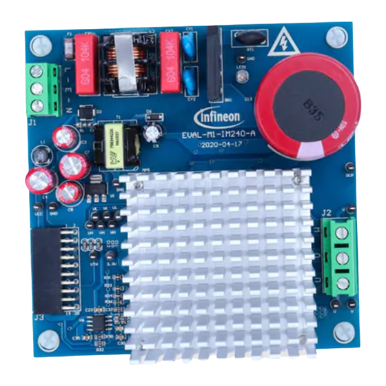
- Page 9 EVAL-M1-IM240-A User Manual iMOTION™ Modular Application Design Kit Main features of EVAL-M1-IM240-A Figure 3 and Figure 4 hint out the functional groups of the EVAL-M1-IM240-A evaluation board. 1. CIPOS™ Micro IPM and Heatsink. 2. Motor phase connector (J2) 3. J3-20 pin iMOTION™ MADK-M1 interface connector for controller board...
-
Page 10: Pin Assignments
EVAL-M1-IM240-A User Manual iMOTION™ Modular Application Design Kit Pin assignments Pin assignments General information about the connectors of the EVAL-M1-IM240-A evaluation board is reported. Table 3 includes the details of the AC input connector J2. Table 3 J2- AC line connector S. - Page 11 EVAL-M1-IM240-A User Manual iMOTION™ Modular Application Design Kit Pin assignments Name Connectors 15 V Supply User Manual Revision 1.0 2020-07-10...
-
Page 12: Getting Started With Eval-M1-Im240-A
Figure 5 System connection example using EVAL-M1-101T and EVAL-M1-IM240-A 1. Get the latest “IMC101T-T038 MCE Software Package” available on www.infineon.com/imotion-software web page. 2. Connect PC-USB connector on the on-board-debugger to the PC via USB cable. 3. Connect EVAL-M1-101T’s M1 20-pin interface connector (J2) to power board (For example EVAL-M1-IM240-A, see Figure 5). - Page 13 EVAL-M1-IM240-A User Manual iMOTION™ Modular Application Design Kit Getting started with EVAL-M1-IM240-A 7. Start MCEDesigner tool and open MCEDesigner default configuration file (.irc) for IMC101T-T038 controller (IMC101T_Vxxx.irc) by clicking “File” > “Open”. IMC101T_Vxxx.irc file is included in ”IMC101T-T038 MCE Software Package” downloaded in step 1. 8.
-
Page 14: Imotion™ Development Tools And Software
“Welcome Page” for MCEWizard, where the MADK control board or power board can be selected through the pull-down list. Infineon keeps releasing new MADK controller and power boards. Therefore, it could happen that some of the newest power boards are not pre-configured in the MCEWizard tool and cannot be selected through the pull-down menu. - Page 15 EVAL-M1-IM240-A User Manual iMOTION™ Modular Application Design Kit Getting started with EVAL-M1-IM240-A power board. Similar tables will be available in each control board’s application note. Combination of this table and the corresponding table of the control board provides enough information to setup the MADK-based motor drive system in shortest time.
-
Page 16: Mcedesigner Setup Overview
EVAL-M1-IM240-A User Manual iMOTION™ Modular Application Design Kit Getting started with EVAL-M1-IM240-A 4.2.2 MCEDesigner setup overview After installing MCEDesigner installer, there is a shortcut for MCEDesigner on the windows desktop. Double click the shortcut to open MCEDesigner and then open “IMC101T_xx.irc” file as shown in Figure 8. Figure 8 MCEDesigner’s main display for EVAL-M1-101T To program system-drive parameter file into IMC101T-T038, please click “Tools”... - Page 17 “Start” button to program the parameter file into the IMC101T-T038 IC. Figure 10 Program firmware and parameter in “Program IMC Controller” pop-up window All the latest firmware files for different types of iMOTION motor control ICs are available for download via Infineon iMOTION website (http://www.infineon.com/imotion-software). User Manual Revision 1.0 2020-07-10...
-
Page 18: Schematics And Layout
EVAL-M1-IM240-A User Manual iMOTION™ Modular Application Design Kit Schematics and layout Schematics and layout To meet individual customer requirements and make the EVAL-M1-IM240-A evaluation board a basis for development or modification, all necessary technical data like schematics, layout and components are included in this chapter. -
Page 19: Motor External Current Feedback Configuration And Calculation
EVAL-M1-IM240-A User Manual iMOTION™ Modular Application Design Kit Schematics and layout The high side resistors R20 and R21 for the DC bus sensing resistor divider on the controller board EVAL-M1- IM240-A are 2000 kΩ, and should be configured in MCEWizard as shown in Figure 12. For the low side resistor value, please refer to the user manual of the corresponding control board. - Page 20 EVAL-M1-IM240-A User Manual iMOTION™ Modular Application Design Kit Schematics and layout Figure 14 depicts IU+ current feedback sensing circuity on EVAL-M1-101T evaluation board. Please note that the default external amplification gain is less than 1 for current sense in this evaluation board. +3.3V Current Shunt iMOTION...
-
Page 21: Inverter Overcurrent Protection And Motor Gatekill Configuration
EVAL-M1-IM240-A User Manual iMOTION™ Modular Application Design Kit Schematics and layout 5.1.3 Inverter overcurrent protection and motor Gatekill configuration Figure 16 displays the overcurrent protection circuitry. Figure 16 Motor gatekill configuration on the EVAL-M1-IM240-A evaluation board The inverter output peak current is about 4 A ×... -
Page 22: Emi Filter And Rectifier Circuit
EVAL-M1-IM240-A User Manual iMOTION™ Modular Application Design Kit Schematics and layout EMI filter and rectifier circuit Figure 18 depicts the schematic from the AC line input connector J2 to the rectified DC bus voltage. This circuitry includes a passive EMI filter consisting of elements CX1, CX2, L2, CY1 and CY2, a 4 A/600 V rectifier block BR1 and a NTC resistor RT1 for surge current protection. -
Page 23: Inverter Section Using Cipos™ Micro
EVAL-M1-IM240-A User Manual iMOTION™ Modular Application Design Kit Schematics and layout Inverter section using CIPOS™ Micro The inverter section is implemented using the CIPOS™ Micro IPM as sketched in Figure 19. The module includes a combination of low VCE (sat) Trench IGBT technology and the industry benchmark rugged half-bridge drivers. ... -
Page 24: Auxiliary Power Supply
Auxiliary power supply Figure 20 depicts the schematic of the auxiliary power supply for the EVAL-M1-IM240-A board. The circuit includes the latest CoolSET 5 of Infineon and flyback topology, directly output 15 V and 6 V. V is connected to the gate drivers inside the CIPOS™... -
Page 25: Schematics For Eval-M1-Im240-A
EVAL-M1-IM240-A User Manual iMOTION™ Modular Application Design Kit Schematics and layout Schematics for EVAL-M1-IM240-A Figure 21 displays the AC linear section schematic for EVAL-M1-IM240-A. 8103 - 1mH, 2A 15D-9 104/X2 104/X2 4A/600V RJ55S-10.00-08P 1.00M, 1W 220uF, 450V 11nF/500V 11nF/500V LED1 222/Y2 222/Y2 Figure 21... - Page 26 EVAL-M1-IM240-A User Manual iMOTION™ Modular Application Design Kit Schematics and layout The inverter section schematic for EVAL-M1-IM240-A is provided in Figure 23. Figure 23 The inverter section schematics for EVAL-M1-IM240-A evaluation board User Manual Revision 1.0 2020-07-10...
-
Page 27: Layout
EVAL-M1-IM240-A User Manual iMOTION™ Modular Application Design Kit Schematics and layout Layout The layout of this board can be used for different voltage or power classes. The PCB has two electrical layers with 35 µm copper by default and its size is 100 mm × 100 mm. The PCB board thickness is 1.6 mm. Get in contact with our technical support team to get more detailed information and the latest Gerber files. - Page 28 EVAL-M1-IM240-A User Manual iMOTION™ Modular Application Design Kit Schematics and layout Figure 25 depicts the bottom assembly print of the evaluation board. Figure 25 Bottom assembly print of the EVAL-M1-IM240-A evaluation board User Manual Revision 1.0 2020-07-10...
- Page 29 EVAL-M1-IM240-A User Manual iMOTION™ Modular Application Design Kit Schematics and layout The top layer of the PCB is provided in Figure 26. Figure 26 Top layer of the EVAL-M1-IM240-A User Manual Revision 1.0 2020-07-10...
- Page 30 EVAL-M1-IM240-A User Manual iMOTION™ Modular Application Design Kit Schematics and layout Figure 27 illustrates the bottom layer routing of the PCB. Figure 27 Bottom layer routing of the EVAL-M1-IM240-A User Manual Revision 1.0 2020-07-10...
-
Page 31: Bill Of Materials Of Eval-M1-Im240-A
EVAL-M1-IM240-A User Manual iMOTION™ Modular Application Design Kit Bill of materials of EVAL-M1-IM240-A Bill of materials of EVAL-M1-IM240-A Table 7 provides the complete bill of materials of the evaluation board. Table 7 Bill of materials No Qty Part description Designator Part number Manufacturer RECT BRIDGE GPP 4A 600V GBU GBU406... - Page 32 EVAL-M1-IM240-A User Manual iMOTION™ Modular Application Design Kit Bill of materials of EVAL-M1-IM240-A SERIE 2165S - 5.08 MM - 691216510003S Wurth Electronics Inc. HORIZONTAL CABLE ENTRY WITH RISING CAGE CLAMP - WR-TBL SERIE 2169 - 7.50 MM - HORIZONTAL 691216910003 Wurth Electronics Inc.
- Page 33 TEST POINT PC MINI .040"D WHITE TP1,TP2, 5002 TP3,TP4, TP5,TP6,T P7,TP8,TP9 ,TP10,TP11 ,TP12,TP13 ,TP14,TP15 ,TP16,TP17 IFX1117MEV33HTM Infineon Technologies IC REG LINEAR 3.3V 1A SOT223-4 ICE5GR4780AG Infineon Technologies IC AUX Power PD-DSO-12 IC OptoCoupler SFH617A-3X007 IC TL431DBZR TL431DBZR IC CIPOS Micro Module IM240-M6Z1B/...
-
Page 34: Reference
All listed reference materials are available for download on Infineon’s websitewww.infineon.com/. All the iMOTION MADK evaluation board’s User Manuals are available at www.infineon.com/MADK Attention: Infineon’s product registration is online now. Register your board, and download more information. 3 easy steps to register: 1. Go to www.Infineon.com/ login to myinfineon 2. -
Page 35: Revision History
EVAL-M1-IM240-A User Manual iMOTION™ Modular Application Design Kit Revision history Revision history Major changes since the last revision Version number Revision Date Revision description 2020-07-10 First release User Manual Revision 1.0 2020-07-10... - Page 36 For information on the types Do you have a question about this given in this application note. in question please contact your nearest Infineon document? Technologies office. The data contained in this document is exclusively Email: erratum@infineon.com...
Need help?
Do you have a question about the iMOTION EVAL-M1-IM240-A and is the answer not in the manual?
Questions and answers