Table of Contents
Advertisement
Quick Links
UG2020-15
EVAL-M1-101TF user guide
iMOTION™ Modular Application Design Kit
About this document
Scope and purpose
This user guide provides an overview of the evaluation board EVAL-M1-101TF including its main features, key
data and mechanical dimensions.
EVAL-M1-101TF is an evaluation-board as part of the iMOTION™ modular application design kit (MADK). This
board features and demonstrates Infineon's advanced motion control engine (MCE 2.0) technology for
permanent-magnet motor drives over the full speed range.
The evaluation board EVAL-M1-101TF was developed to support customers during their first steps designing
applications using permanent magnet motors via sensorless sinusoidal control.
Intended audience
This user guide is intended for all technical specialists who have a knowledge of motor control and high-power
electronics converters. The board is intended for use under laboratory conditions.
This board will be used during design-in, for evaluation and measurement of characteristics, and proof of data
sheet specifications.
Evaluation Board
This board will be used during design in, for evaluation and measurement of characteristics, and proof of data
sheet specifications.
Note:
PCB and auxiliary circuits are NOT optimized for final customer design.
User guide
Please read the Important notice and the Safety precautions and the Warnings
V. 1.0
www.infineon.com
page 1 of 32
2020-11-03
Advertisement
Table of Contents

Related Manuals for Infineon EVAL-M1-101TF


Summary of Contents for Infineon EVAL-M1-101TF
-
Page 1: About This Document
About this document Scope and purpose This user guide provides an overview of the evaluation board EVAL-M1-101TF including its main features, key data and mechanical dimensions. EVAL-M1-101TF is an evaluation-board as part of the iMOTION™ modular application design kit (MADK). This board features and demonstrates Infineon’s advanced motion control engine (MCE 2.0) technology for... -
Page 2: Important Notice
Boards provided by Infineon Technologies. The design of the Evaluation Boards and Reference Boards has been tested by Infineon Technologies only as described in this document. The design is not qualified in terms of safety requirements, manufacturing and operation over the entire operating temperature range or lifetime. -
Page 3: Safety Precautions
EVAL-M1-101TF user guide iMOTION™ Modular Application Design Kit Safety precautions Safety precautions Note: Please note the following warnings regarding the hazards associated with development systems. Table 1 Safety precautions Warning: The DC link potential of this board is up to 310 V . -
Page 4: Table Of Contents
2.4.2 Motor external current feedback configuration and calculation ........... 15 2.4.3 Motor internal current feedback amplifier gain configuration ............17 EVAL-M1-101TF analog inputs and their MCEWizard setup ..............18 2.5.1 DC bus-sensing configuration ......................18 2.5.2 NTC shutdown value calculation and configuration ..............19 2.5.3... -
Page 5: The Board At A Glance
The PC interface provides a UART connection to the MCE. The EVAL-M1-101TF evaluation board is available from Infineon. The features of this board are described in the main features chapter of this document, whereas the remaining paragraphs provide information to enable the customers to copy, modify and qualify the design for production according to their own specific requirements. -
Page 6: Block Diagram
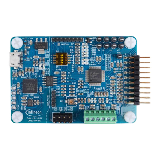
IMC101T-F048 also employs a unique single shunt current reconstruction circuit in addition to a leg shunt current sensing circuit to eliminate additional analog/digital circuitry. Figure 2 Typical application block diagram using IMC101T-F048 Figure 3 points out the functional groups on the top side of the EVAL-M1-101TF board. 1. On-board debugger 2. USB interface connector (X101) 3. - Page 7 Modular Application Design Kit The board at a glance Main features EVAL-M1-101TF is an evaluation control board for motor control applications. The kit demonstrates Infineon’s motion control IC technology. Main features of the IMC101T-F048 motion control IC include: MCE (motion control engine) as ready-to-use solution for variable speed drives ...
-
Page 8: Board Parameters And Technical Data
EVAL-M1-101TF user guide iMOTION™ Modular Application Design Kit The board at a glance Board parameters and technical data Table 2 depicts the key specifications of the evaluation board EVAL-M1-101TF. Table 2 EVAL-M1-101TF board specifications Parameter Symbol Conditions / comments Value... -
Page 9: System And Functional Description
System and functional description Commissioning In order to run the motor system, a combination of the iMOTION™ MADK control board (EVAL-M1-101TF) and the matching MADK power board (with M1 connector) is required. The iMOTION™ software tools, MCEDesigner and MCEWizard, are also required to initially set up the system, as well as to control and fine-tune the system performance to match users’... -
Page 10: Imotion™ Development Tools And Software
The iMOTION™ development tool installers for MCEDesigner and MCEWizard are available for download via the Infineon iMOTION website (http://www.infineon.com/imotion-software). All supported tools and software variants are listed there. Please visit this page periodically to check for tool/software updates. The isolated on-board debugger provides the USB to UART bridge between the PC and the target iMOTION™... - Page 11 EVAL-M1-101TF user guide iMOTION™ Modular Application Design Kit System and functional description Table 3 MCEWizard setup overview table Parameter Value Comment Power board selecting MADK power board name If no, select similar power board to modify Motor 1 shunt configuration...
-
Page 12: Mcedesigner Setup Overview
MCEDesigner and then open “IMC101T_xx.irc” file (which was included in the “IMC101T-F048 MCE Software Package” installed earlier, as instructed in Chapter 2.2) shown in Figure 8. Figure 8 MCEDesigner’s main display for EVAL-M1-101TF User guide 12 of 32 V. 1.0... - Page 13 EVAL-M1-101TF user guide iMOTION™ Modular Application Design Kit System and functional description MCEDesigner programmer function can be used to program IMC101T-F048 firmware and/or system parameters. To call up this function, click on the “Tools” menu and then select “Programmer” in the pull-down list. The pop-up window “Program IMC controller”...
- Page 14 IMC101T-F048 controller, the 3.3 V DC voltage needs to be supplied to the controller portion of the EVAL-M1-101TF. This voltage can either be supplied by the power board (MADK power boards are designed to supply the 3.3 V to the control board through M1 or M3 connector) or by feeding the 3.3 V DC voltage to the control board through some of the available 3.3 V access/test points, if the...
-
Page 15: Description Of The Functional Blocks
System and functional description Description of the functional blocks This chapter covers the hardware design of the EVAL-M1-101TF in more detail. To enable users to make the EVAL-M1-101TF evaluation board a basis for a new development or modification of their own systems, all necessary technical data such as schematics, layout and components are also included in this chapter. - Page 16 Figure 12 Current shunt feedback and sample timing Figure 13 depicts IU+ current feedback sensing circuity on EVAL-M1-101TF evaluation board. Please note that the default external amplification gain is less than 1 for current sense in this evaluation board. Figure 13...
-
Page 17: Motor Internal Current Feedback Amplifier Gain Configuration
Modular Application Design Kit System and functional description Figure 14 Current feedback configuration in MCEWizard for EVAL-M1-101TF and EVAL-M1-05-065D 2.4.3 Motor internal current feedback amplifier gain configuration For the current feedback, the iMOTION™ controller on this board has the internal amplifier which has four programmable gain settings: 1x, 3x, 6x and 12x. -
Page 18: Eval-M1-101Tf Analog Inputs And Their Mcewizard Setup
2.5.1 DC bus-sensing configuration The low-side resistor R4 for the DC bus-sensing resistor divider on the controller board EVAL-M1-101TF is 13.3 kΩ, and should be configured in MCEWizard as shown in Figure 17. For the high-side resistor value, please refer to the User Guide of the corresponding power board. -
Page 19: Ntc Shutdown Value Calculation And Configuration
Figure 18. For the pull-up resistor on the evaluation power board and the NTC value, please refer to the power board’s User Guide. The value of the pull-up resistor on EVAL-M1-101TF is 4.87 kΩ (see Figure 16). ��... - Page 20 EVAL-M1-101TF user guide iMOTION™ Modular Application Design Kit System and functional description Figure 19 Analog VSP control input mode configuration Figure 20 explains that there are three input thresholds (percentage of controller supply voltage VDD) that are used to define the relationship between the Vsp input voltage and the “TargetSpeed”.
- Page 21 EVAL-M1-101TF user guide iMOTION™ Modular Application Design Kit System and functional description Figure 21 Three input thresholds configuration for VSP analog input control mode For analog Vsp control input mode, the motor speed can be calculated by measuring the frequency of PGOUT signal output of control IC IMC101T-F048.
- Page 22 EVAL-M1-101TF user guide iMOTION™ Modular Application Design Kit System and functional description ���������� ������������������ ( ���� ) ∗ ������ ���������� ���������� ( ������ ) = ���������� ������ �������������������� For example, the PGOUT frequency is about 80 Hz and the pulse per revolution is 6, the motor speed will then be 800 RPM.
-
Page 23: System Design
Gerber generation are done in Altium Designer. Customers who are interested in the original Altium format files or pdf files for better clarity can visit www.Infineon.com. Schematics Figure 24 shows the schematic of the EVAL-M1-101TF evaluation board with the IMC101T-F048 controller. Figure 24 The schematics for the EVAL-M1-101TF evaluation board PCB layout The layout of this board can be used for different voltages or power classes of the power board. - Page 24 EVAL-M1-101TF user guide iMOTION™ Modular Application Design Kit System design Figure 25 Top overlay print of the EVAL-M1-101TF evaluation board Figure 26 depicts the bottom assembly print of the evaluation board. Figure 26 Bottom overlay print of the EVAL-M1-101TF evaluation board The top layer routing of the PCB is provided in the following Figure 27.
- Page 25 EVAL-M1-101TF user guide iMOTION™ Modular Application Design Kit System design Figure 27 Top layer routing of the EVAL-M1-101TF Figure 28 illustrates the bottom layer routing of the PCB. Figure 28 Bottom layer routing of the EVAL-M1-101TF User guide 25 of 32 V.
-
Page 26: Bill Of Materials
This evaluation design kit provides the complete bill of materials for the EVAL-M1-101TF board. The complete bill of material is available on the download section of the Infineon homepage. A log-in is required to download this material. Some key components are shown on Error! Reference source not found.. -
Page 27: Connector Details
Bill of materials Connector details Key information about the connections of the EVAL-M1-101TF evaluation board is described below. Table 5 provides the pin assignments of the iMOTION™ MADK-M1 20-pins interface connector J1. This connector is the interface to the power board. - Page 28 Speed feedback to external Analog reference External VDD External power supply for FG signal The EVAL-M1-101TF supports the use of both digital and analog Hall sensors. Table 9 includes the details of the Hall sensor interface connector. Table 9 J5- Hall sensor Input...
- Page 29 EVAL-M1-101TF user guide iMOTION™ Modular Application Design Kit Bill of materials Table 10 Parameter page selection for GPIO GPIO input Parameter block PAR3 PAR2 PAR1 PAR0 Table 11 list some LEDs on this board. Table 11 Function of on-board LEDs...
-
Page 30: References And Appendices
EVAL-M1-101TF user guide iMOTION™ Modular Application Design Kit References and appendices References and appendices References Infineon-IMC100-DS-v01_05-EN.pdf iMOTION™ MCE Software Reference Manual MCEWizard User Guide MCEDesigner User Guide Ordering information Base Part Number Package Standard Pack Orderable Part Number Form Quantity... -
Page 31: Revision History
EVAL-M1-101TF user guide iMOTION™ Modular Application Design Kit Revision history Revision history Document Date of release Description of changes version 2020-11-03 First release User guide 31 of 32 V. 1.0 2020-11-03... - Page 32 WARNINGS 81726 Munich, Germany Due to technical requirements products may contain dangerous substances. For information on the types in question please contact your nearest Infineon © 2020 Infineon Technologies AG. Technologies office. All Rights Reserved. Except as otherwise explicitly approved by Infineon...
- Page 33 Mouser Electronics Authorized Distributor Click to View Pricing, Inventory, Delivery & Lifecycle Information: Infineon EVAL-M1-101TFTOBO1...
Need help?
Do you have a question about the EVAL-M1-101TF and is the answer not in the manual?
Questions and answers