
Related Manuals for Cygnus 1 Ex


Summary of Contents for Cygnus 1 Ex
- Page 1 Cygnus 1 Ex Operating Manual Cygnus 1 Ex Intrinsically Safe Ultrasonic Thickness Gauge Operating Manual & Instructions for Safety Cygnus 1 Ex Operating Manual (EN)(Issue 3).docx November 2022 Page 1 of 91...
- Page 2 Important Notices The Instructions for Safety section at the beginning of this manual must be followed when using the Cygnus 1 Ex ultrasonic thickness gauge in an explosive environment. The correct use of Cygnus ultrasonic thickness gauges requires identification of the correct equipment for the specific application coupled with an appropriately trained and qualified operator or technician.
-
Page 3: Table Of Contents
Cygnus 1 Ex Operating Manual Contents Section 1 - Introduction ................. 7 Cygnus 1 Ex ....................7 Cygnus Instruments ..................8 Contact Details ................... 8 Kit Contents ....................9 Gauge Kit ....................9 Register your Gauge ..................9 Section 2 - Instructions for Safety..............10 Important Notice .................. - Page 4 Single Element Probes ................25 Protective Membranes ................25 Changing the Protective Membrane ............27 Measuring Higher Temperatures .............. 28 Summary of Cygnus Probe Types ..............28 Twin Element probes ................28 Single Element probes ................28 The ‘Probe Type’ Code ................29 Controls ......................
- Page 5 Cygnus 1 Ex Operating Manual Two Point Calibration Procedure ..............44 Setting the Velocity of Sound ..............46 Probe Settings ..................... 48 Setting the Probe Type ................48 Auto Detect ..................48 Manually Setting the Probe Type ............. 48 Probe Zeroing (twin element probes) ............49 Probe Gain Auto-Setting ................
- Page 6 Cygnus 1 Ex Operating Manual Dynamic Freeze Mode ................69 Adjusting Gain and TCG ................70 Measurement Setups ..................71 User Access ....................71 Adding Users .................... 73 Gauge Menu ....................74 Menu Operation ..................74 Menu Group - Datalogging................74 No Record is Open .................
-
Page 7: Section 1 - Introduction
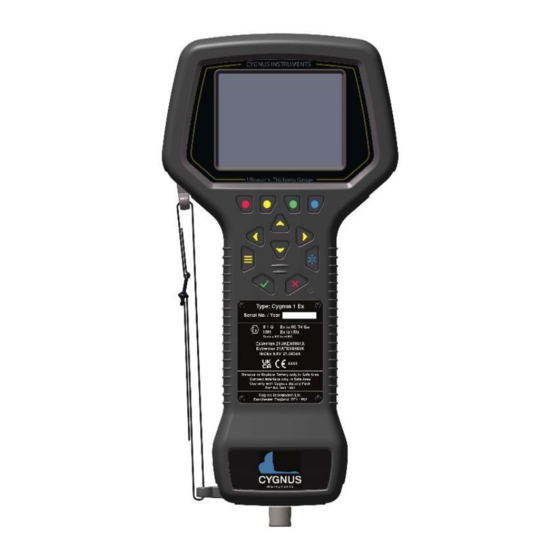
Cygnus 1 Ex Operating Manual Section 1 - Introduction Cygnus 1 Ex The Cygnus 1 Ex Ultrasonic Thickness Gauge is a rugged, handheld, battery- powered, intrinsically safe instrument designed for taking reliable thickness measurements using ultrasound in Zone 0 (Class 1 Division 1) Explosive Atmospheres. -
Page 8: Cygnus Instruments
Dorchester, Dorset, DT1 1PW England. Website: www.cygnus-instruments.com Tel: 00 44 (0) 1305 265533 sales@cygnus-instruments.com For all Cygnus offices in UAE, USA, Singapore, and Authorised Cygnus Service Centres and Distributors please refer to the Cygnus website Worldwide Distribution page. https://cygnus-instruments.com/about-us/worldwide-distributors/ Page 8 of 91... -
Page 9: Kit Contents
10. Declarations of Conformity (EU, UK) 11. One 15mm or ½” Steel Test Block Register your Gauge Please take a moment to register your gauge with Cygnus and start your 3-year warranty, by registering you can receive updates on • Technical Information •... -
Page 10: Section 2 - Instructions For Safety
Important Notice The following information must be read and followed by all users of the Cygnus 1 Ex ultrasonic thickness gauge when used in an explosive environment. The protective features of the device may be impaired if it is used in a manner not specified by Cygnus Instruments. -
Page 11: Ntrl / Met Marking
Equipment Use • The Cygnus 1 Ex is an intrinsically safe portable measuring instrument. • The Cygnus 1 Ex must be used in accordance with IEC / EN 60079-14. • The Cygnus 1 Ex EPL is • Suitable zones are... -
Page 12: Standards Used For Ex Certification
• UL 61010-1, 3rd Ed: 2012. • UL 60079-0, 7th Ed: 2019. • UL 60079-11, 6th Ed: 2013. Battery Pack • Use only with Cygnus Battery Pack part nos. 060-1003 (ATEX/IECEx/UKEX) or 060-2003 (NRTL) • Lithium-Ion, Secondary Cell • Nominal Output Voltage = 7.4 V •... -
Page 13: Assembling The Instrument
Cygnus 1 Ex Operating Manual Assembling the Instrument The Cygnus 1 Ex instrument comprises of three parts, shown below Cygnus Ex Instrument Body Battery Pack Ultrasonic Probe Fig 1. Cygnus 1 Ex Instrument Parts Fitting the Battery Pack Never remove or replace the battery pack in an Explosive Atmosphere. -
Page 14: Connecting The Ultrasonic Probe
Fig 2. Cygnus 1 Ex Battery Pack Fitting. Connecting the Ultrasonic Probe Only Cygnus Ex Ultrasonic Probes designed to for this product can be used in an Explosive Atmosphere as they contain energy limiting devices not found in standard probes. -
Page 15: Charging The Battery
Cygnus 1 Ex Operating Manual Fig 3. Cygnus 1 Ex Probe Connector. It is safe to unplug and replace Cygnus Ex Ultrasonic Probes in an Explosive Atmosphere. Charging the Battery The battery pack must only be removed and charged in a Safe Area. -
Page 16: Connecting To A Computer
Cygnus 1 Ex USB Interface. You must only connect the Cygnus 1 Ex Instrument to a computer in a Safe Area. To transfer data between the Cygnus 1 Ex instrument and a Windows ® computer, a USB Interface module is supplied. This module also acts as a Ex Protection Barrier to protect the instrument from over-voltages from a faulty computer. -
Page 17: Connecting To The Instrument
The lead coming from the USB Interface has a silver connector that is plugged into the data port on the rear of the Cygnus 1 Ex instrument. • Push-down the sealing cap on the data port connector on the rear of the Cygnus 1 Ex instrument to expose the connector socket, •... -
Page 18: Cleaning The Instrument
Cygnus 1 Ex Operating Manual Cleaning The Instrument See the section on Cleaning on page 80. Page 18 of 91... -
Page 19: Section 3 - Gauge Features
Cygnus 1 Ex Operating Manual Section 3 – Gauge Features The Cygnus 1 Ex gauge is available to order in four variants, you can change the variant or add certain features at a later date by purchasing an Update Code from Cygnus. -
Page 20: Upgrading
Cygnus 1 Ex Operating Manual Upgrading Purchasing an Update Code To purchase an Update Code, you will need to provide the serial number of the gauge, its current variant and feature code. To find the Variant, Serial Number and Feature Code of the gauge, navigate to Menu->Setup->Gauge Info. -
Page 21: Section 4 - Operating Instructions
The performance of any thickness gauge and its ability to get a reliable measurement depends on selecting the right ultrasonic probe for the application and conditions. The Cygnus 1 Ex gauge is therefore offered with a selection of probes suitable for most thickness gauging applications. -
Page 22: Measurement Modes
Cygnus 1 Ex Operating Manual Steels Non to 3 mm+ Multiple Echo Moderate (0.12”+) Steels Non to 0.8 mm+ Single Echo Heavy (0.03”+) Steels Non to 1.0 mm+ Single Echo Heavy (0.03”+) Steels Non to 1.5 mm+ Single Echo Heavy (0.06”+) -
Page 23: Echo-Echo Mode (Ee) (Mode 3)
Echo-echo mode is not able to verify its measurements unlike Multiple echo mode, therefore it is liable to give incorrect readings. But as the Cygnus 1 Ex gauge has an A-Scan display you can use this to visually decide if the measurement given is correct. -
Page 24: Measuring Non-Metals
Cygnus 1 Ex Operating Manual Use the same rules as steels when selecting a suitable probe. The gauge will ideally be re-calibrated to suit the metal being measured, or the standard velocity of sound for the specific material would be entered into the gauge. -
Page 25: Surface Temperatures
Single Element Probes Protective Membranes All Cygnus single element probes have a soft face and therefore are fitted with a Polyurethane Membrane which provides better contact on rough surfaces and protects the probe face from wear, prolonging the life of the probe. -
Page 26: Fig 8. Single Element Probe Membrane Locking Key
Cygnus 1 Ex Operating Manual Fig 8. Single Element Probe Membrane Locking Key Page 26 of 91... -
Page 27: Changing The Protective Membrane
Cygnus 1 Ex Operating Manual Changing the Protective Membrane Unscrew the Knurled Ring from the end of the Probe. Use the Membrane Key to unscrew the Locking Ring from inside the Knurled Ring. The old membrane can then be removed and discarded. -
Page 28: Measuring Higher Temperatures
Cygnus 1 Ex Operating Manual Measuring Higher Temperatures The standard polyurethane membrane fitted to the single element probes are suitable for measuring surface temperatures up to 70°C (160°F). For measuring higher temperatures Teflon membranes are available and suitable for surface temperatures up to 150°C (300°F) with intermittent contact. Contact Cygnus instruments to order Teflon membranes. -
Page 29: The 'Probe Type' Code
Cygnus 1 Ex Operating Manual 5.0 MHz 1 to 50 mm Small diameter tubes 0.25” 0.04 to 2” Thin metals Coated metals The ‘Probe Type’ Code Size 6mm / ¼” ingle or Frequency in MHz 8mm / 0.32” Crystal 13mm / ½”... -
Page 30: Changing Values
Cygnus 1 Ex Operating Manual Fig 10. Function Keys In the above example, • Red function key = Zero • Yellow function key = Gain • Green function key = Range • Blue function key = Zoom Changing Values Numbers Numeric values are adjusted using a common dialog. -
Page 31: Lists
Cygnus 1 Ex Operating Manual Lists Items in Lists are selected using a common dialog. Use the ▲ ▼ navigation keys to select an item in the list. Press the √ key to save the choice or press the X key to cancel. -
Page 32: Status Information
Cygnus 1 Ex Operating Manual You can use the ▲ navigation key to move up into the ‘text’ area where a thin Edit Cursor can be positioned using the ►◄ navigation keys so you can edit the text at that point, use the ▼ navigation key to move back to select a character. -
Page 33: Measurement Screens
Cygnus 1 Ex Operating Manual 250C High Temp Compensation is active, set to 250°C 1-PT Cal One-point calibration active 2-PT Cal Two-point calibration active Material Material Calibration active Measurement Screens Depending on the features available in the gauge, there are 4 possible measurement screens available. -
Page 34: Operation
Turning the Gauge On To turn the gauge on press the power X key once. After a short delay, a start-up screen is displayed followed by the Cygnus logo. The gauge will then display a measurement screen. Turning the Gauge Off To turn the gauge on press the power X key for 2 seconds until the “Shutdown... -
Page 35: Echo Indicators In Multiple Echo Mode
Cygnus 1 Ex Operating Manual Apply ultrasonic couplant to the test surface. Place the probe-face on the clean, lubricated test surface and make firm contact applying gentle pressure. The gauge will display a thickness measurement. (Or an indication of Echo Strength if no valid measurement has been found in Multiple Echo mode). -
Page 36: Measurement Stability Indication In Se & Ee Modes
Cygnus 1 Ex Operating Manual 2 steady + 1 Bar Flashing: Only 2 echoes detected 3 steady + 1 Bar Flashing: 3 echoes detected but they are not matched Measurement Stability Indication in SE & EE Modes To help indicate a stable Single Echo or Echo-Echo measurement – and thus probably reliable –... -
Page 37: Measurement Freeze Feature
Cygnus 1 Ex Operating Manual If the measurement remains stable for 2 consecutive seconds, then the measurement will change to black or green. Stable is defined as; the thickness measurement changing no more than + or - the Resolution setting. -
Page 38: A-Scan Range
Cygnus 1 Ex Operating Manual measurements are sensible and therefore reliable. With some experience a user can quickly decide if the measurement is correct. Fig 18. The A-Scan screen displaying a good echo signal. A-Scan Range The X axis range of the A-scan graph can be set manually or automatically by pressing the Range function key. -
Page 39: A-Scan Zoom
Cygnus 1 Ex Operating Manual A-Scan Zoom You can Zoom in on echo signals using the Zoom function key. Pressing the Zoom function key will step through each zoom mode (depending on the measuring mode set.) Zoom Mode Details Zoom Off... -
Page 40: A-Scan Rectification
Cygnus 1 Ex Operating Manual Fig 22. A-Scan Half Grid. Fig 23. A-Scan Full Grid. A-Scan Rectification The A-Scan graph can show a RF or rectified signal independently of the measurement, there are four options. • RF (No Rectification) • Full Wave Rectification •... -
Page 41: Calibration
Instructions for calibrating the gauge can be found on page 44. Calibration Options The Cygnus 1 Ex gauge is supplied calibrated with a calibration certificate. The Gauge will have been calibrated to measure thickness through steel (grade S355JO) with a velocity of sound of 5920 m/s. -
Page 42: Calibrating To A Known Thickness (Single Or 1 Point)
Cygnus 1 Ex Operating Manual be more accurate than using a ‘general’ velocity value. For calibration instructions see page 42. If there is no test sample available, the gauge can be calibrated by setting the Velocity of Sound directly. A table on page 85 at the back of this manual lists common materials and their velocity of sound value. -
Page 43: Two Point Calibration
Cygnus 1 Ex Operating Manual While holding the probe firmly on the sample and while a steady thickness measurement is displayed. “1 Point Cal – Waiting Thick Ref.” message is displayed Use the up and down ▲▼ navigation keys to adjust the thickness to the required value. -
Page 44: Ladder Step Wedges
Cygnus 1 Ex Operating Manual When performing a two-point calibration both sample thicknesses should be made from the same material. The temperature of the sample material should be the close to the temperature of the material to be measured. The gauge will automatically compensate for v-path error in addition to either single- or two-point calibrations. - Page 45 Cygnus 1 Ex Operating Manual Access the Menu and scroll down to the ‘Calibration’ group. Then scroll right to the ‘2 Point Cal’ item. Press the √ key to start. Start with the thick sample – the maximum thickness. While holding the probe firmly on the thick sample and while a steady thickness measurement is displayed.
-
Page 46: Setting The Velocity Of Sound
Cygnus 1 Ex Operating Manual While holding the probe firmly on the thin sample and while a steady thickness measurement is displayed. Use the up and down ▲▼ navigation keys to adjust the thickness to the required value. When the correct measurement is... -
Page 47: Fig 26. Velocity Of Sound Value '5920 M/S
Cygnus 1 Ex Operating Manual Access the Menu and scroll down to the Calibration group. Then scroll right and select Velocity. Press the √ key to set the Velocity If there has been a previous Calibration, a message will warn that changing the velocity will alter the calibration. -
Page 48: Probe Settings
Auto Detect There is an Auto Detect feature that can automatically detect most twin element Cygnus probes when they are connected to the gauge, however this does not work for single element probes. Access the Menu and scroll down to the Probe group. -
Page 49: Probe Zeroing (Twin Element Probes)
Cygnus 1 Ex Operating Manual Probe Zeroing (twin element probes) Twin element probes must be zeroed to compensate for any wear or operating temperature changes. The gauge will always perform a Probe Zero when first turned on or when a twin element probe is connected. -
Page 50: Probe Gain Auto-Setting
Cygnus 1 Ex Operating Manual If the Probe Zero fails a message will be displayed. • Check the probe has not been unplugged or the cable is damaged/faulty. • The probe face must be clean and in the air. • Are you using a non-Cygnus... -
Page 51: Twin Element Probes
Cygnus 1 Ex Operating Manual Twin Element Probes The gain is optimised when the probe is placed on the Test Block supplied with the kit. From the Menu, select Probe, then Autoset Gain Follow the instructions, adding couplant to the Test Block, then press the √... -
Page 52: Datalogging Basic
Cygnus 1 Ex Operating Manual Datalogging Basic • Linear Records • Comments Datalogging Advanced • Linear, Grid 2D and Multipoint Records • Comments • Radial Points • Templates Record Types There are four types of Record that can be created. -
Page 53: Creating A New Record
Cygnus 1 Ex Operating Manual • Minimum and Reference thickness limits can be specified in a record. • Radial Points can be added to any Linear or Grid measurement point. • You can start logging measurements from any location in the record. -
Page 54: Creating A New Record Using A Template
Cygnus 1 Ex Operating Manual Creating a New Record using a Template From the Menu, select Data Logging, then New Record. Press the √ key to start. Select Template as the Record Type. Select the Template you want to use. -
Page 55: Reference And Minimum Thicknesses
Cygnus 1 Ex Operating Manual Fig 30. Record Name parameter. Reference and Minimum Thicknesses Each record can have an optional Reference and Minimum thickness value applied to it. When logging thickness measurements these limits are used to colour the measurement values and in the case of the minimum limit alert the user if the measurement is under that limit by way of a red colour highlight. -
Page 56: Logging Measurements
Cygnus 1 Ex Operating Manual First move right across the columns, then move down to the next row. Repeat. Up Left, Up Left This is a Vertical Measurement pattern. First move up through the rows, then move left to the next column. Repeat. - Page 57 Cygnus 1 Ex Operating Manual Obstruction preventing access to measurement points. plate Measurement points Measurement point logged as Obstructed logged as No-reading (OBS) (NOR) In a measurement screen, make sure there is no thickness measurement displayed – LOS is displayed - the probe is in air and its face is clean.
-
Page 58: Logging No-Reading (Nor) Points
Cygnus 1 Ex Operating Manual Logging No-Reading (NOR) Points When you can’t get a thickness measurement at the current location, but need to record something in the record, you can choose to log a NOR (No Reading) measurement. In a measurement screen and have no thickness measurement value displayed. -
Page 59: Adding Comments
Cygnus 1 Ex Operating Manual Use the ◄►▲▼ navigation keys to highlight the required measurement point You can also press the Jump To function key to specify a specific coordinate in the record. Pressing the √ key to jump to the coordinates entered. -
Page 60: Adding Radial Points
Cygnus 1 Ex Operating Manual Use the up and down ▲▼ navigation keys to highlight the required comments, using the function keys to select/clear as required. Measurement points with comments have a small in the lower left part of the measurement cell. - Page 61 Cygnus 1 Ex Operating Manual 8 additional radial measurement points. plate After logging a measurement, from the Menu select Data Logging, then Radial Points, then press the √ key. Next select the number of Radial Point to add. Log the Radial Point measurements ‘around’...
-
Page 62: Protecting Records
Cygnus 1 Ex Operating Manual Protecting Records You can protect a datalogger record to prevent any further changes being made to it. Records can be locked or unlocked, when records are created, they are un- locked so you can log measurement into them, when you have finished a record you can lock it to prevent any accidental changes or deletion. -
Page 63: Deleting All Records
Cygnus 1 Ex Operating Manual Select the record to delete, then press the Delete function key. You will be prompted to conform the deletion – press the √ key to confirm or the X key to cancel. Deleting All Records First close any Open record. -
Page 64: B-Scans
Cygnus 1 Ex Operating Manual From the Menu, select Data Logging, then Save a Template, then press the √ key. Give the template a meaningful name so you can identify it easily. B-Scans The B-Scan feature can be used to take a series of continuous thickness measurements and display the results graphically to represent a cross section through the material. -
Page 65: Performing A Scan
Cygnus 1 Ex Operating Manual Fig 32. B-Scan Example. • B-Scans can be auto-paused when the ultrasound signal is lost – LOS Mode. • B-Scans have a measurement Scan Range to scale the Y axis. • B-Scans have an optional Scan Length to scale the X axis. -
Page 66: Loading A B-Scan
Cygnus 1 Ex Operating Manual Place the probe and start measuring, carefully moving the probe across the surface at a constant speed. The scan trace will start to build. Lifting the probe off the surface will pause the scan (if LOS Mode is set to Pause). -
Page 67: Manual Measurement Mode
Cygnus 1 Ex Operating Manual From the Menu, select B-Scan, then Open B-Scan File, then press the √ key. Select the B-Scan, then press the √ key. Manual Measurement Mode For the advanced user, the gauge can take measurements using conventional Gates which can be manually configured to suit the application. -
Page 68: Enabling Manual Measuring Mode
Cygnus 1 Ex Operating Manual Enabling Manual Measuring Mode From the Menu, select Measurement, then Mode, then press the √ key. Select the Manual Mode then press the √ key. The measurement menu now allows selection of the manual mode features. -
Page 69: Gate Modes
Cygnus 1 Ex Operating Manual Select the Gate A or Gate B function key. Use the function keys to select and adjust a Gate setting. Start = Start Position Width = Gate Width Level = Gate Level in % Back = Back to Gate select. -
Page 70: Adjusting Gain And Tcg
Cygnus 1 Ex Operating Manual The Gate Level is set to 20% The signal is then Frozen. The Gate Level is now adjusted to 71%, and the Gate Trigger point now moves as its triggers by a later ½ cycle. The measurement value increases to 10.0mm. -
Page 71: Measurement Setups
You can save and load measurement setups from the Measurement menu. User Access The Cygnus 1 Ex gauge has a User Access feature that can be used to prevent access to certain features depending on the access level of the current user. -
Page 72: Fig 34. Example Of User Login To Access A Datalogging Function
Cygnus 1 Ex Operating Manual The following table shows what access level is required to access a feature. Feature Level 1 Level 2 Level 3 Probe Menu √ √ √ Measurement Menu √ √ √ Datalogging √ √ √ B-Scan √... -
Page 73: Adding Users
Cygnus 1 Ex Operating Manual Adding Users Users are added from the Setup menu, under the User List item. When the user list is empty and Admin login will be required, the default Admin PIN number is “1305”, this is fixed and cannot be changed as it provides a backdoor way-in should you forget a PIN number. -
Page 74: Gauge Menu
Cygnus 1 Ex Operating Manual Gauge Menu Menu Operation All the gauge’s features and settings can be accessed via the Menu, to display the Menu just press the Menu key from any measurement screen. The menu is split into two columns, the left column are the Groups, the right column are the selected Group’s Items. -
Page 75: A Record Is Open
Cygnus 1 Ex Operating Manual A Record is Open Close Record Close the current datalogging record. Add Comment Add a Comment to a specific measurement point in the current datalogging record. Navigate through the record to select the measurement point. -
Page 76: Menu Group - Limits
Cygnus 1 Ex Operating Manual Measurement group items when the Manual Mode Measurement feature is enabled. Measure With Selects which Gate/Gates are used for thickness measurements. GateA SE = SE measurement using Gate A GateA EE = EE measurement using Gate A GateAB EE = EE measurement using Gate A &... -
Page 77: Menu Group - High Temp
Cygnus 1 Ex Operating Manual Menu Group - High Temp Enable Set the High Temperature Compensation feature On or Off. Surface Temp Set the surface temperature for compensation. Temp Units Select between C and F units for surface temperature. Coefficient Sets the temperature compensation coefficient value. -
Page 78: Menu Group - Display
Cygnus 1 Ex Operating Manual Scan Length Sets a length of a scan so an estimation of position can be made. This expects the scan to made at a constant speed. Scan Direction Sets the scan direction as shown on the B-Scan graph. -
Page 79: Menu Group - Setup
Cygnus 1 Ex Operating Manual Menu Group - Setup Power Save Sets the Power Saving Timer. When the gauge is Idle, not taking measurements or being used, to save battery power the screen brightness is reduced and eventually the gauge is turned off. -
Page 80: Section 5 - Information
To ensure Ex compliance all repairs must be carried out by Cygnus Instruments. The Cygnus 1 Ex kit is covered by a full manufacturers no-quibble 1 year warranty, this can be extended to 3 years at no extra cost by registering your product on the Cygnus Website. -
Page 81: Part Numbers
Cygnus 1 Ex Operating Manual Part Numbers This table lists all the parts of the Cygnus 1 Ex product kit that have been approved for use as part of the Ex-Certificates. Item Part Number Part Number (ATEX/IECEx/UKEX) (NRTL) Cygnus 1 Ex Instrument Body... -
Page 82: Update Software
Before updating your gauge note the model and serial number of the gauge (Menu -> Setup -> Gauge Info). You can then check on the Cygnus website if your gauge has the latest firmware version, and if not proceed to download the update software. - Page 83 Cygnus 1 Ex Operating Manual Cygnus 1 Ex Technical Specifications Through Coating Multiple-Echo mode with Single element 0° probe; Measurements • Through coating measurement for coatings up to 3 mm thick as standard depending on coating velocity. • Deep Coat mode provides ability to measure through thicker coatings depending on coating material.
- Page 84 Cygnus 1 Ex Operating Manual Cygnus 1 Ex Technical Specifications Resolution Single Echo and Echo-Echo measurement modes; 0.1 mm [0.005”] High 0.01 mm [0.001”] Multiple Echo measurement modes; 0.1 mm [0.005”] (measurement > 120 mm) Medium 0.05 mm [0.002”] (measurement < 120 mm) Accuracy ±0.1 mm (±0.004”) or 0.1% of thickness measurement...
-
Page 85: Table Of Sound Velocities
Cygnus 1 Ex Operating Manual Cygnus 1 Ex Technical Specifications Calibration Mechanisms Not required for Multiple Echo mode. Automatic V-path correction for twin element probes. Option of two-point calibration for twin element probes. Display & Recall Facilities Display Response Time... -
Page 86: Reading Conversions
Cygnus 1 Ex Operating Manual Brass (Naval) 4330 0.1705 0.731 Brass (CuZn30) 4700 0.1850 0.794 Copper 4700 - 5000 0.1850 – 0.1969 0.794 – 0.845 Core Ten 5920 0.2331 1.000 Grey Cast Iron 4600 0.1811 0.777 Inconel 5700 0.2244 0.963... - Page 87 Cygnus 1 Ex Operating Manual where : T = true thickness of Copper being measured t = actual reading obtained f = Conversion Factor (from table) = Sound Velocity in Copper : 4700 m/s COPPER = Sound Velocity in Steel : 5920 m/s...
-
Page 88: Recycling And Disposal (Ec Countries)
WEEE collection facilities. This product may also be returned to the agent or manufacturer who supplied it for safe end-of-life disposal. Cygnus Instruments Ltd registration number for The WEEE Directive is WEE/HE1274RU. Page 88 of 91... -
Page 89: Warranty Information
CYGNUS in relation to the Product. 5. Except as expressly set forth above or in the CYGNUS Terms of Sale, subject to which the Products were purchased, all warranties, conditions or other terms implied by Statute or Common Law are extended to the fullest extent permitted by law. -
Page 90: Revision History
Fig 2. Cygnus 1 Ex Battery Pack Fitting............. 14 Fig 3. Cygnus 1 Ex Probe Connector..............15 Fig 4. Cygnus 1 Ex Battery Charger Cradle and Battery........16 Fig 5. Cygnus 1 Ex USB Interface..............17 Fig 6. - Page 91 Cygnus 1 Ex Operating Manual Fig 27. A Linear Record .................. 52 Fig 28. A Grid-2D Record ................52 Fig 29. A Multipoint Record ................52 Fig 30. Record Name parameter..............55 Fig 31. Grid Record and Grid Patterns.............. 55 Fig 32.
Need help?
Do you have a question about the 1 Ex and is the answer not in the manual?
Questions and answers