
Related Manuals for Cygnus ROV UTM


Summary of Contents for Cygnus ROV UTM
- Page 1 Cygnus ROV UTM Ultrasonic Thickness Gauge Operating Manual Covers Instrument Model: M5-ROV-ASCAN with SD2D-DCW Probe Doc No. Cygnus ROV UTM Operation Manual (Issue 7).docx June 2022...
-
Page 2: Table Of Contents
Cygnus ROV UTM - Operating Manual Contents 1. Introduction ..............5 Cygnus ROV UTM ..............5 Register your Gauge ..............6 Kit Contents ................7 Optional Items ..............7 2. System Overview .............. 8 Subsea Instrument ..............8 Ultrasonic Probe ..............8 P50 Probe Handler ............... 10 3. - Page 3 Cygnus ROV UTM - Operating Manual Manual Gain ..............31 Velocity of Sound and Material List ........31 Measurement range for A-Scan Range........31 7. Calibration and Zero ............33 Why should I Calibrate? ............33 Calibrating to a Known Thickness ........... 34 Zeroing the Probe ..............
- Page 4 Included Maximum Surface Contact Temperature to Probe Specifications Issue 6 03-Nov-20 Updated for change in Probe Connector (CRE). Updated for Serial Interface (RS-232). Issue 7 06-Jun-22 Change of product name to “Cygnus ROV UTM” Added product registration info. Page 4 of 60...
-
Page 5: Introduction
Cygnus ROV UTM - Operating Manual 1. Introduction Cygnus ROV UTM The Cygnus ROV UTM – ROV Mountable Thickness Gauges are rugged, compact instruments designed for reliable ultrasonic thickness measurements. The instrument is pressure rated to a maximum depth of 3000 meters sea water (300 bar). -
Page 6: Register Your Gauge
Cygnus ROV UTM - Operating Manual Register your Gauge Register your gauge to receive updates on gauge firmware and to register your 3-year warranty. Registration is quick and easy, go to this web address; https://cygnus-instruments.com/service/product-registration/ Product Registration Link QR Page 6 of 60... -
Page 7: Kit Contents
Cygnus ROV UTM - Operating Manual Kit Contents The Cygnus ROV UTM system is supplied as a complete kit in a transportation case Cygnus ROV UTM Subsea Instrumentation Unit SD2C-DAW 2.25 MHz Single Element Delay Line Probe with cable and connector. Fitted in P50 Probe Handler. -
Page 8: System Overview
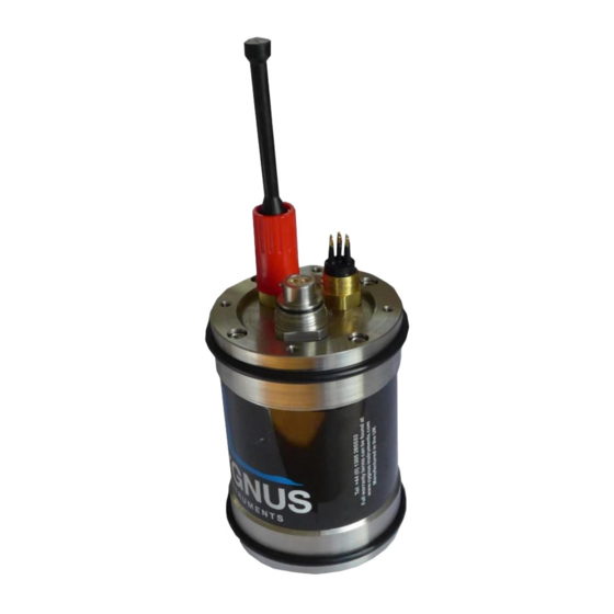
Cygnus ROV UTM - Operating Manual 2. System Overview Subsea Instrument The system is supplied ready to use. All that is required is to make the necessary electrical connections between the subsea unit and the ROV Craft and the top side computer. - Page 9 Cygnus ROV UTM - Operating Manual SD2C-DCW Ultrasonic Probe. The probe is supplied with 5m of cable, protected by an outer reinforced air hose. Each end has a stainless steel bracket which is attached by M5 screws and nuts. Ultrasonic Probe Cable Mounting Bracket - P50 Probe Handler End.
-
Page 10: P50 Probe Handler
Cygnus ROV UTM - Operating Manual Connection to the subsea unit is by a multi-pin connector secured by a brass threaded collar. The instrument is designed only to be used with ultrasonic probes supplied by Cygnus Instruments. P50 Probe Handler The ‘P50’... - Page 11 Cygnus ROV UTM - Operating Manual Ultrasonic Probe and P50 Probe Handler. P50 Probe Handler on ø130mm Pipe. Page 11 of 60...
- Page 12 Cygnus ROV UTM - Operating Manual Ultrasonic Probe Alignment on ø130mm Pipe Surface. Ultrasonic Probe Cable Fitted to the P50 Probe Handler. Page 12 of 60...
-
Page 13: Connecting The System Together
Cygnus ROV UTM - Operating Manual 3. Connecting the System Together Subsea Instrument There are two connectors on the subsea instrument, marked • POWER COMMS • PROBE Power and Comms On the subsea instrument power and comms are connected via the 6-way SubConn ©... -
Page 14: Connecting The Ultrasonic Probe
Cygnus ROV UTM - Operating Manual Pin No. Colour Description Pinout Black Ground White 12-24V DC Input RS-232 TXD Green RS-232 RXD Orange No connect Blue No connect Connecting the Ultrasonic Probe The ultrasonic probe is connected to the subsea instrument using the threaded connector marked ‘PROBE’. -
Page 15: Securing The Cables
Cygnus ROV UTM - Operating Manual Securing the Cables The system is supplied with a Cable Support Cage which is used to secure the probe cable bracket and cable-tie the power and comms cable. The cable support cage is bolted to the top of the subsea enclosure using four M5 cap-head screws. -
Page 16: Connecting Topside
Cygnus ROV UTM - Operating Manual Connecting Topside At the surface, the RS-232 Comms link should be wired from the multiplexer port to the RS-232 to USB converter lead. There are three connections; TXD, RXD and Ground. You must connect the ground. -
Page 17: System Operation
Cygnus ROV UTM - Operating Manual 4. System Operation On the deck before launching the ROV Before launching the ROV, test the system is operating and you can take a thickness measurement using the 15mm Test Block from the kit. Hold the test block against the probe face and use couplant gel to ultrasonically couple the test block to the probe. -
Page 18: Taking Thickness Measurements Subsea
Cygnus ROV UTM - Operating Manual Taking Thickness Measurements Subsea Surface Preparation Water jetting the surface to SA1 is recommended. The instrument will not measure through barnacles or similar hard encrustations. You must therefore remove any hard marine growth before attempting a thickness measurement. -
Page 19: Start Cyglink Topside
The Probe Must Be Aligned Perpendicular in Both Axes. Start CygLink Topside Run the Cygnus CygLink program from its desktop shortcut. To Connect to the Subsea Instrument, from the menu select; Connect -> Connect to Gauge See Connecting to the on page 39. -
Page 20: Taking Measurements
Cygnus ROV UTM - Operating Manual Taking Measurements For best results set the Measuring Mode to Auto SE/EE/ME, see Measure Mode on page 30. This will let the instrument decide the best measurement to make. The ROV operator should position the ultrasonic probe on the... - Page 21 Cygnus ROV UTM - Operating Manual Valid SE Measurement of 12.0mm. A single yellow diamond marks the Measurement Point in SE Mode. The screen shown below show a valid measurement of 21.7mm and the A-Scan graph shows a signal marked with two yellow diamonds to indicate the EE measurement points.
- Page 22 Cygnus ROV UTM - Operating Manual Valid EE Measurement of 21.7mm. The screen shown below show a valid measurement of 11.4mm and the A-Scan graph shows a signal marked with three yellow diamonds to indicate the ME measurement points. Valid ME Measurement of 11.4mm.
-
Page 23: Logging Measurements
Cygnus ROV UTM - Operating Manual Logging Measurements You can Log a measurement at any time by clicking the Log button, the displayed measurement and A-Scan will be saved in to the current survey. Logging a Measurement. You can view a logged measurement at any time by double clicking on the measurement in the Measurements tab on the right. -
Page 24: Manual Gain Control
Cygnus ROV UTM - Operating Manual Manual Gain Control For the experienced UT operator there is a Manual Gain control feature that allows the operator to adjust the gain value in dB. This can be useful when obtaining a thickness measurement is difficult in Auto gain mode. -
Page 25: Using The Display Freeze
Cygnus ROV UTM - Operating Manual • c1 = Cursor 1 Value (yellow) • c2 = Cursor 2 Value (blue) • d = Cursor 2 – Cursor 1 (difference between) You can Log any cursor measurement into the Survey by clicking the Log button next to the cursor values. - Page 26 Cygnus ROV UTM - Operating Manual Frozen A-Scan Graph. Page 26 of 60...
-
Page 27: Measurement Modes
Cygnus ROV UTM - Operating Manual 5. Measurement Modes The Measure Mode determines how the instrument uses the ultrasound signals to get a thickness measurement. There are three measurement modes used in this instrument; • Single Echo Mode • Echo-Echo Mode •... -
Page 28: Echo-Echo Mode (Ee)
Cygnus ROV UTM - Operating Manual Echo-Echo Mode (EE) Echo-Echo Mode (ISO 16809 Mode 3) measures from the 1 back- wall echo (E1) to the 2 back-wall echo (E2). Advantages: • Ignores surface coatings up to 1mm thick • Better measurement accuracy Disadvantages •... -
Page 29: Auto Ee/Se/Me Mode
Cygnus ROV UTM - Operating Manual Disadvantages • Not good on heavy corrosion • Can be difficult to get a measurement Auto EE/SE/ME Mode This mode lets the instruments decide the best measurement mode to use. First it will try to get a ME measurement, then try to get an EE measurement then finally try to get an SE Measurement. -
Page 30: Measurement Settings In Cyglink
Cygnus ROV UTM - Operating Manual 6. Measurement Settings in CygLink The measurement settings panel in CygLink has all the settings that control how the system measures thickness. In CygLink from the menu bar select Setup -> Measurement Settings, this will display the screen below. -
Page 31: Manual Gain
Cygnus ROV UTM - Operating Manual • Echo-Echo • Multiple Echo • Auto SE/EE/ME See Measurement Modes on page 27. Manual Gain When the tick-box is un-checked the Gain is set Automatically by the subsea instrument. This is the default and recommended setting. - Page 32 Cygnus ROV UTM - Operating Manual • AUTO The gauge automatically adjusts the A-scan range • 15 mm (0.6”) • 30 mm (1.2”) • 60 mm (2.4”) Page 32 of 60...
-
Page 33: Calibration And Zero
Cygnus ROV UTM - Operating Manual 7. Calibration and Zero Why should I Calibrate? Ultrasonic thickness gauges measure time in order to measure the thickness of the material being tested. The rely on the principal that sound travels through a material at a constant velocity or speed. -
Page 34: Calibrating To A Known Thickness
Cygnus ROV UTM - Operating Manual Calibrating to a Known Thickness This method of calibrating the gauge is more accurate than using a standard velocity value as the gauge calculates the velocity of sound for the sample material. Calibrating to a Known Thickness Accurately measure the 10.80... -
Page 35: Zeroing The Probe
Cygnus ROV UTM - Operating Manual Calibrating to a Known Thickness Either set the material thickness in the “Set To” and press Set or adjust the velocity if the material velocity is known. Close the window by pressing Save once calibration is complete. - Page 36 Cygnus ROV UTM - Operating Manual Zero Probe button. Page 36 of 60...
-
Page 37: Cyglink
Installing CygLink CygLink V5 is supplied with the kit on a USB Flash Drive, or it can be downloaded from the Cygnus Instruments website. If you want to make sure you are installing the latest version, then downloading from the website is the best option. -
Page 38: Com Port Numbers
Cygnus ROV UTM - Operating Manual COM Port Numbers CygLink should automatically find the COM port number assigned to the USB converter when you click “connect” so you don’t need to search for the port number Windows has assigned. Setting the COM Port Manually If CygLink fails to locate the correct COM port number you can set in manually from the File ->... -
Page 39: Connecting To The Instrument
Cygnus ROV UTM - Operating Manual Windows ® Device Manager Connecting to the Instrument First time USB Connection When you first connect the gauge to the computers USB port Windows will search for a suitable driver, you may notice this message from the taskbar;... -
Page 40: Connecting The Instrument To Cyglink For The First Time
Cygnus ROV UTM - Operating Manual Connecting the Instrument to CygLink for the First Time Turn on the system power Run CygLink V5 From the Menu click; Connect └ Discover new Gauge and Connect Page 40 of 60... -
Page 41: Connecting To The Instrument Afterwards
Cygnus ROV UTM - Operating Manual CygLink will search all the available Com ports listening for a Cygnus gauge. If a instrument is detected, then it will connect and save these settings for next time. When connected you should see details of the gauge in the status bar at the bottom and ‘Connected’... -
Page 42: Disconnecting From The Gauge
Cygnus ROV UTM - Operating Manual Disconnecting from the Gauge To disconnect from the instrument simply click from the menu; Connect └ Disconnect from Gauge Manual Connection Settings If you need to manually set the connection settings then select the Connection Settings option from the Connect menu, here you can specify the COM Port number, gauge type and baud rate. -
Page 43: Cyglink Surveys And Data Logging
Cygnus ROV UTM - Operating Manual CygLink Surveys and Data Logging CygLink have the facility to store logged thickness measurements in a single Survey file. These measurements are organised into Survey Groups, each Survey Groups can contain any number of thickness measurements. -
Page 44: Editing The Survey Details
Cygnus ROV UTM - Operating Manual File Menu. Editing the Survey Details The Survey contains all the Groups and is used to save all the data. You can also add details to the Survey that will be printed at the beginning of the PDF report. -
Page 45: Editing The Survey Group Details
Cygnus ROV UTM - Operating Manual Editing the Survey Group Details To view and edit the survey Group details right click on the records number and select properties. To create a new Survey Group select in the File menu New Survey Record. -
Page 46: Logging Measurements Directly In Cyglink
Cygnus ROV UTM - Operating Manual Logging Measurements Directly in CygLink You can use CygLink to log the displayed topside thickness measurements into a Survey so they can be presented in the Survey report. Clicking the Log button next to the thickness measurement will create a new record and add a measurement into the group. -
Page 47: Adding Comments Or Notes To A Measurement
Cygnus ROV UTM - Operating Manual Measurement Comments Screen. Adding Comments or Notes to a Measurement You can add your own quick text Notes to any logged thickness measurement, just select the measurement point in the list and right click to display more options. -
Page 48: To Change The Com Port Number Assigned By Windows
Cygnus ROV UTM - Operating Manual To Change the COM Port number assigned by Windows ® Depending on a variety of factors, Windows ® may sometimes assign a COM Port number that is too high or unusual to be easily remembered. -
Page 49: Cyglink Trouble Shooting
Cygnus ROV UTM - Operating Manual 3. On the “Advanced Settings” form you can change the COM Port number. Finish by clicking the “OK” button. CygLink Trouble Shooting Connection Problems – USB Drivers If you are unable to get a connection the first thing to try is updating the USB drivers for the Serial to USB converter. -
Page 50: Wiring Problems
Cygnus ROV UTM - Operating Manual The Serial to USB converter used for the Cygnus ROV UTM gauge is manufactured by FTDI. You can search the web for the latest drivers from FTDI; Type this into Google search “FTDI US232R”... -
Page 51: Care And Servicing
Repairs There are no user serviceable parts inside the instrument. Therefore all repair work should be carried out by Cygnus Instruments or by an Authorised Cygnus Service dealer. Returning the Gauge for Servicing A full Manufacturer’s Factory Service is available from Cygnus Instruments. -
Page 52: Technical Specifications
Cygnus ROV UTM - Operating Manual 10. Technical Specifications Cygnus ROV UTM Technical Specifications General Attributes Size 105 mm x 110 mm x 35 mm (W x H x D) (4.1 in x 4.3 in x 1.4 in) Weight In Air Gauge body 3.7kg max (8.2 lb.) - Page 53 Cygnus ROV UTM - Operating Manual Cygnus ROV UTM Technical Specifications Display Type of Display Remote Display Unit Display Size Transmitter Shape of Pulse Square Pulse Energy : Voltage (peak- 70 V p-p to-peak) Pulse Energy : Rise Time 3 ns (max)
-
Page 54: Table Of Sound Velocities
Cygnus ROV UTM - Operating Manual 11. Table of Sound Velocities Velocities will vary according to the precise grade and processing conditions of the material being measured. This table is included as a guide only. Wherever possible, the Instrumnet should always be calibrated on the material under test. -
Page 55: Reading Conversions
Cygnus ROV UTM - Operating Manual Velocity of Sound (V) Conversion Material Factor (f) in/us Stainless Steel 316 5750 0.2264 0.971 F51 Duplex Steel 0.956 – 5715 - 5750 0.225 – 0.2264 UNS S31803 0.971 Core Ten Steel 5920 0.2331 1.00... -
Page 56: Recycling And Disposal (Ec Countries)
Cygnus ROV UTM - Operating Manual 12. Recycling and Disposal (EC Countries) The WEEE Directive (Waste Electrical and Electronic Equipment 2002/96.EC) has been put into place to ensure that products are recycled using best available treatment, recovery and recycling techniques to ensure human health and high environmental protection. -
Page 57: Electrical Connections
Cygnus ROV UTM - Operating Manual 13. Electrical Connections Power & Comms Port (Bulkhead plug) MCBH6M (mates with MCIL6F). The picture below is shown looking into the bulkead connector. Pin No. Colour Description Pinout Black Ground White 12-24V DC Input... -
Page 58: Cygnus Instruments
Cygnus ROV UTM - Operating Manual 14. Cygnus Instruments Cygnus Instruments Limited, founded in 1983, pioneered the development of the Digital Ultrasonic Multiple-Echo Technique used for measurement through coatings. Our philosophy is to work closely our customers to provide high quality products, engineered to serve heavy industry &... -
Page 59: Warranty Information
6. Except in respect of death or personal injury caused by the negligence of Cygnus, Cygnus shall not be liable to the Purchaser or to any other person by reason of any representation (unless fraudulent), or any implied warranty, condition or other term,... -
Page 60: Index
Cygnus ROV UTM - Operating Manual 16. Index A-Scan Display Disposal, 56 Range, 31 Multiple Echo, 28 Calibration Nosecone Conversion Factor, 55 Fitting, 14 Known Thickness, 34 Recycling, 56 Cleaning, 51 Repair, 51 CygLink Service, 51 COM Port, 38 Single Echo, 27...
Need help?
Do you have a question about the ROV UTM and is the answer not in the manual?
Questions and answers