Icom IC-905 Basic Manual
All mode transceiver
Hide thumbs
Also See for IC-905:
- Connection manual (2 pages) ,
- Advanced manual (215 pages) ,
- Reference manual (31 pages)
Table of Contents
Advertisement
Quick Links
Advertisement
Table of Contents

Related Manuals for Icom IC-905


Summary of Contents for Icom IC-905
- Page 1 BASIC MANUAL ALL MODE TRANSCEIVER |905...
-
Page 2: Supplied Accessories
Thank you for choosing this Icom product. This SUPPLIED ACCESSORIES product is designed and built with Icom’s state of the art technology and craftsmanship. With proper care, this product should provide you with years of trouble- free operation. This product combines traditional analog technologies with the Digital Smart Technologies for Amateur Radio (D-STAR), for a balanced package. -
Page 3: Explicit Definitions
• Force majeure, including, but not limited to, fires, earthquakes, storms, floods, lightning, or other natural disasters, disturbances, riots, war, or radioactive contamination. • The use of Icom transceivers with any equipment that is not manufactured or approved by Icom. -
Page 4: Voice Coding Technology
#8,595,002, #8,359,197, #8,315,860, • 5701.6305 MHz #8,200,497, #7,970,606, #6,912,495 B2. TRADEMARKS Icom and the Icom logo are registered trademarks of Icom Incorporated (Japan) in Japan, the United States, the United Kingdom, Germany, France, Spain, Russia, Australia, New Zealand, and/or other countries. -
Page 5: Important Notes
IMPORTANT NOTES D When using the GPS receiver D Electromagnetic Interference • The GPS antenna is attached to the RF unit’s When using the transceiver in the 2.4 GHz or 5.6 GHz top panel. Therefore, when the GPS receiver is band, pay attention to the following: activated, do not cover the antenna with anything These bands are also used by other devices, such as... -
Page 6: About The Touchscreen
Icom website. beep tone ON. https://www.icomjapan.com/support/ Enter “IC-905” into the Search box in the site. Touch If the display is touched briefly, one short beep • Basic manual (This manual) sounds. -
Page 7: About The Instructions
ABOUT THE INSTRUCTIONS The Advanced and Basic manuals are described in 3. Touch [▲] or [▼] to scroll through the items. the following manner. L You can also rotate to scroll through the items. “ ” (Quotation marks): Used to indicate icons, setting items, and screen titles displayed on the screen. -
Page 8: Keyboard Entering And Editing
KEYBOARD ENTERING AND EDITING Keyboard types: You can select the Full Keyboard or Tenkey pad in “Keyboard Type” on the FUNCTION screen. (p. 8-6) » SET > Function > Keyboard Type L You can also temporarily switch in the QUICK MENU screen by pushing L You can select the full keyboard layout in “Full Keyboard Layout”... -
Page 9: Usable Characters
USABLE CHARACTERS You can enter and edit the items in the following table. Maximum Menu Category Item Selectable characters characters My Station My Call Sign A to Z, 0 to 9, (space), / 8 + 4 TX Message [AB] [ab] [12] [!″#] Network Set Network Name A to Z, 0 to 9, ! "... - Page 10 TABLE OF CONTENTS IMPORTANT ..............i Selecting the operating band ......3-2 FEATURES ..............i Selecting the operating mode ......3-2 SUPPLIED ACCESSORIES ........i Setting the frequency ........3-3 EXPLICIT DEFINITIONS ..........ii D Using the Main Dial ........3-3 DISPOSAL ..............ii D About the Tuning Step function .....
- Page 11 Split Lock function ........... 4-12 10 MAINTENANCE ..........10-1 Cleaning ............10-1 Operating CW ..........4-12 D Setting the CW pitch control ......4-12 Replacing fuse ..........10-1 D Setting the key speed ........4-12 Resetting ............10-1 D Using the Break-in function ......4-13 D Partial reset ..........
- Page 12 Immediately turn OFF the power and/or remove CAUTION: DO NOT use non-Icom microphones. the DC power cable. Contact your Icom dealer or Other microphones have different pin assignments, distributor for advice. and may damage the transceiver.
- Page 13 DO NOT push PTT unless you actually intend to transmit. NEVER leave the transceiver in an insecure place to avoid use by unauthorized persons. Turn OFF the transceiver’s power and disconnect the DC power cable when you will not use the transceiver for long period of time.
-
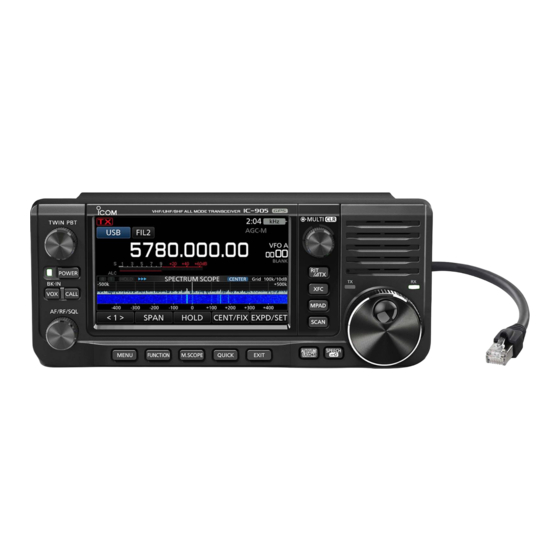
Page 14: Panel Description
PANEL DESCRIPTION Front panel (Controller) 1 PASSBAND TUNING CONTROL 8 FUNCTION KEY (p. 1-7) (p. 4-5) Push to open the FUNCTION screen. • Push to toggle between “PBT1” and “PBT2,” then rotate to adjust the shift value. 9 MINI SCOPE KEY (p. - Page 15 PANEL DESCRIPTION Bottom panel (Controller) Front panel (Controller) You can attach a third party mounting base using 15 MEMO PAD KEY screw holes* on the bottom panel. • Push to sequentially call up the contents in the * AMPS hole pattern Memo Pads.
- Page 16 (p. 13-1) Connect a supplied speaker microphone’s speaker 7 SEND JACK [SEND] (p. 13-2) plug. (3.5 mm (1/8 inch)) Connect to control transmit with non-Icom external units. 13 MICROPHONE JACK [MIC] (p. 13-1) Connect a supplied speaker microphone’s microphone plug. (2.5 mm) 14 DC POWER JACK [DC 13.8 V] (p.
-
Page 17: Speaker Microphone
PANEL DESCRIPTION Top panel/Bottom panel (RF unit) Speaker microphone Top panel Mic element Bottom panel 1 [PTT] SWITCH Hold down to transmit, release to receive. NOTE: To maximize the readability of your signal, hold the microphone 5 to 10 cm (2 to 4 inches) from your mouth, and then speak at your normal voice level. -
Page 18: Touch Screen Display
PANEL DESCRIPTION Touch screen display 5 6 7 8 9 10 11 12 13 14 15 16 1 TX STATUS INDICATOR 8 GPS ALARM ICON Displays the transmit status. Displayed when the GPS Alarm function is ON. • is displayed while transmitting. 9 NETWORK CONTROL ICON •... - Page 19 PANEL DESCRIPTION Touch screen display 17 18 19 20 21 22 P ¥ 17 MODE INDICATOR (p. 3-2) S VFO/MEMORY ICONS (p. 3-1) Displays the selected operating mode. Displays “VFO A” or “VFO B” when the VFO mode is selected, and displays “MEMO”...
- Page 20 PANEL DESCRIPTION Touch screen display D FUNCTION screen D MENU screen Function name Status Lights blue or orange when in use z Push to open the FUNCTION screen in z Push to open the MENU screen in the the selected mode. selected mode.
- Page 21 PANEL DESCRIPTION Multi-function dial Touch screen display D Multi-function menus When the Multi-function menu is closed, the control can be enabled to adjust functions by pushing or touching the item for 1 second on the Multi- function menus. The function is displayed in the upper right corner of Touch the edge to the screen.
-
Page 22: Installation And Connections
INSTALLATION AND CONNECTIONS Selecting a location Connecting a microphone Select a location for the transceiver that allows Plug the microphone into the [MIC-SP] jack and the adequate air circulation, free from extreme heat, cold, [MIC] jack, and attach the microphone’s cable to the or vibration, and other electromagnetic sources. -
Page 23: Connecting An External Dc Power Supply
• DC 13.8 V (Capacity: At least 5 Amps) time. • A power supply with an over current protective line, and low voltage fluctuation or ripple. Non-Icom DC power supply Attach the Ferrite EMI filter to the DC 13.8 V/5.5 A or more DC power cable. -
Page 24: Basic Operation
When first applying power Using the VFO mode Before turning ON your transceiver for the first time, The IC-905 has 2 Variable Frequency Oscillators make sure all connections are correctly made. (VFO), “A” and “B.” Having 2 VFOs is convenient to... -
Page 25: Selecting The Operating Band
BASIC OPERATION Selecting the operating band Selecting the operating mode Do the following steps to change the operating band. You can select between the SSB (LSB/USB), SSB data (LSB-DATA/USB-DATA), CW, CW reverse, RTTY, 1. Touch the MHz digits. (Example: 145) RTTY reverse, AM, AM data (AM-DATA), FM, FM data (FM-DATA), DV, DD*, and ATV* modes. -
Page 26: Setting The Frequency
BASIC OPERATION Setting the frequency D Using the Main Dial D About the 1 MHz Step Tuning function 1. Select the desired operating band. (p. 3-2) You can use the maximum tuning step of 1 MHz. 2. Rotate • The frequency changes according to the selected Touch the MHz digits for 1 second to turn the 1 MHz Tuning Step. -
Page 27: D About The 1/4 Tuning Function
BASIC OPERATION Setting the frequency D About the 1/4 Tuning function D Directly entering a frequency SSB-D, CW, and RTTY modes You can set the frequency without rotating With the Tuning Function OFF, turn ON the 1/4 Tuning by directly entering it using the keypad. function to reduce the tuning speed to 1/4 of the normal speed, for finer tuning. - Page 28 BASIC OPERATION Setting the frequency D Directly entering a frequency Entering the Split Frequency Offset Selecting a Memory channel by number 1. Touch the MHz digits. (Example: 145) 1. Select the Memory mode. (p. 3-1) • Opens the BAND STACKING REGISTER screen. 2.
-
Page 29: D Band Edge Beep
BASIC OPERATION Setting the frequency D Band Edge Beep Editing a Band Edge You will hear a Band Edge Beep and (with a You can edit a band edge entered as a default, or dotted line) will be displayed when you tune into or out change the band edge frequencies. - Page 30 BASIC OPERATION Setting the frequency D Band Edge Beep Deleting a Band Edge Entering a new Band Edge You can delete band edges you no longer need. You can enter new Band Edge frequencies into a blank band edge line. 1.
-
Page 31: Dial Lock Function
BASIC OPERATION Setting the frequency Inserting a Band Edge Resetting all band edges to their defaults You can insert a new Band Edge line, and enter new The steps below will reset all the band edges to their band frequencies, between two entered band edges. initial settings. -
Page 32: Rf Gain And Sql Level
BASIC OPERATION RF gain and SQL level Adjusting the microphone gain 1. Push 1. Set the operating band and mode to SSB, AM, 2. Touch an item to adjust. (Example: RF GAIN) FM, DV, or ATV. (p. 3-2) 2. Push to open the Multi-function menu. -
Page 33: D Meter Display Selection
BASIC OPERATION Meter display D Meter display selection Displays the receiving signal strength level. Displays the relative RF output power. You can display one of the 6 different transmit parameters (Po, SWR, ALC, COMP, Vd, and Id) for SWR: Displays the SWR of the antenna at the your convenience. -
Page 34: Adjusting The Transmit Output Power
BASIC OPERATION Adjusting the transmit output Transmit Power Limit function power The Transmit Power Limit function limits the output power to the preset level for each band. Before transmitting, monitor your selected operating frequency to make sure you do not cause 1. -
Page 35: Receiving And Transmitting
RECEIVING AND TRANSMITTING Preamplifiers Attenuator 144, 430, and 1200 MHz bands 144, 430, and 1200 MHz bands The preamp amplifies received signals in the receiver The Attenuator prevents a desired signal from front end to improve the signal-to-noise ratio and becoming distorted when a very strong signal is near sensitivity. -
Page 36: D Rit Monitor Function
RECEIVING AND TRANSMITTING RIT function Monitor function The Receiver Incremental Tuning (RIT) function SSB, CW, RTTY, AM, FM, DV, and ATV modes compensates for differences in frequencies of other The Monitor function enables you to monitor your stations. transmit audio. Use this function to check the The function shifts your receive frequency up to voice characteristics while adjusting transmit audio ±9.99 kHz without shifting the transmit frequency. -
Page 37: Afc Function
RECEIVING AND TRANSMITTING AFC function FM and DV modes The Automatic Frequency Control (AFC) function tunes the receive frequency to the incoming signal. L This function activates regardless of the squelch condition. L When the Split function is ON, the transmit frequency is not tuned into the incoming signal. -
Page 38: Agc Function Control
RECEIVING AND TRANSMITTING AGC function control D Setting the AGC time constant SSB, CW, RTTY, and AM modes The Automatic Gain Control (AGC) function controls You can set the preset AGC time constant to a desired receiver gain to produce a constant audio output level, value. -
Page 39: Using The Digital Twin Pbt
IF passband width, using the Digital Twin electronically shifting the IF frequency to slightly PBT. above or below the IF center frequency. The IC-905 uses the digital function using the FPGA (Field Programmable Gate Array) filtering method. L Each mode memorizes the PBT setting. -
Page 40: Selecting The If Filter Shape
SSB, CW, RTTY, and AM modes Mode IF filter Selectable range (steps) The IC-905 has 3 IF filter passband widths for each FIL 1 (3.0 kHz) mode, and you can select them on the FILTER 50 Hz to 500 Hz (50 Hz)/ FIL 2 (2.4 kHz) -
Page 41: D Setting The Manual Notch Filter
RECEIVING AND TRANSMITTING Notch Filter D Setting the Manual Notch filter SSB, CW, RTTY, AM, and FM modes The IC-905 has Auto Notch and Manual Notch When Manual Notch is selected, adjust the filtered functions. frequency. Auto Notch automatically attenuates beat tones, tuning signals, and so on. -
Page 42: Noise Blanker
RECEIVING AND TRANSMITTING Noise Blanker D Adjusting the NB level and time SSB, CW, RTTY, and AM modes The Noise Blanker eliminates pulse-type noise, such To deal with various types of noise, you can adjust the as the noise from car ignitions. attenuation level and blanking depth and width in the NB menu. -
Page 43: Setting The Transmit Filter Width
RECEIVING AND TRANSMITTING Noise Reduction Setting the transmit filter width SSB, CW, RTTY, AM, FM, DV, and ATV modes SSB mode The Noise Reduction function reduces random noise The transmit filter width for the SSB and SSB-D components and enhances signal audio. modes can be set. -
Page 44: Setting The Speech Compressor
RECEIVING AND TRANSMITTING Setting the Speech Compressor D Using the Speech Compressor function SSB mode The Speech Compressor increases the average RF 1. Touch the Multi-function meter again to display output power, improving readability at the receiving the COMP meter. station. -
Page 45: Split Frequency Operation
RECEIVING AND TRANSMITTING Split frequency operation Split frequency operation enables you to transmit and receive on different frequencies in the same band. There are 2 ways to use Split frequency operation. • Use the Quick Split function. • Use the receive and transmit frequencies set to VFO A and VFO B. The other station Your station VFO A... -
Page 46: Split Lock Function
RECEIVING AND TRANSMITTING Split Lock function Operating CW To prevent accidentally changing the receive D Setting the CW pitch control frequency by releasing while rotating You can set the received CW audio pitch and the CW use the Split Lock function. Using both this function side tone to suit your preference, without changing the and the Dial Lock function enables you to change only operating frequency. -
Page 47: D Using The Break-In Function
The IC-905 is capable of operating in the Semi Break-in and Full break-in modes. 1. Select the CW mode. -
Page 48: D About The Electronic Keyer Function
RECEIVING AND TRANSMITTING Operating CW D About the electronic Keyer function You can set the Memory Keyer function settings, paddle polarity settings, and so on of the Electronic Keyer. 1. Select the CW mode. EDIT 2. Open the KEYER screen. KEYER MEMORY edit menu »... -
Page 49: Scope Operation
SCOPE OPERATION Spectrum scope screen The spectrum scope enables you to display the D Using the Spectrum Scope activity on the selected band, as well as the relative Display the SPECTRUM SCOPE screen. strengths of various signals in that band. »... - Page 50 SCOPE OPERATION Spectrum scope screen D Center mode D Scroll mode Displays signals around the operating frequency Displays signals within a selected span. When the within the selected span. The operating frequency is operating frequency moves outside of the screen, the always displayed in the center of the screen.
-
Page 51: Audio Scope Screen
SCOPE OPERATION Audio scope screen Spectrum scope screen D Touch screen operation This audio scope enables you to display the received signal’s frequency component on the FFT scope, and By touching the FFT scope zone or the waterfall zone its waveform components on the Oscilloscope. The in the SPECTRUM SCOPE screen, the area will be FFT scope also has a waterfall. -
Page 52: About The Sd Cards
L Be sure to check the card You can use an SD card of up to 2 GB, or an SDHC orientation before inserting. of up to 32 GB. Icom has checked the compatibility of the following cards. (As of February 2023) -
Page 53: Saving The Setting Data
SD CARD Saving the setting data Unmounting The Memory channels and the transceiver’s settings Before you remove a card when the transceiver is ON, can be saved onto an SD card. be sure to electrically unmount it, as shown below. Otherwise, the data may be corrupted or deleted. -
Page 54: Gps Operation
L Even when “Position Input” is set to “Manual,” the icon is displayed. » GPS > GPS Set > Position Input Latitude L The IC-905 automatically adjusts the internal reference Longitude Grid Locator frequency using the received GPS data as the default... -
Page 55: Set Mode Description
SET MODE Set mode description You can use the Set mode to set infrequently changed TIP: The Set mode is constructed in a tree structure. values or function settings. You can go to the next tree level, or go back a level, depending on the selected item. -
Page 56: Tone Control/Tbw
SET MODE Function NOTE: The default settings shown below are for the USA transceiver version. The default settings may differ, depending on your transceiver version. » SET > Function Beep Level (Default: 50%) Tone Control/TBW Sets the beep output level. L If “Beep (Confirmation)”... - Page 57 L If an external equipment’s rise time is slower than that and transmit frequencies for the Quick SPLIT function. of the IC-905, a reflected wave is produced, and it may damage the IC-905 or the external device. To prevent SPLIT LOCK...
- Page 58 SET MODE » SET > Function > SPEECH Function SPEECH Language (Default: English) » SET > Function Sets the speech language to English or Japanese. Auto Repeater (Default: ON (DUP)) L This item is displayed in only the USA version. Alphabet (Default: Normal) The Auto repeater function automatically turns the...
-
Page 59: Lock Function
SET MODE » SET > Function AFC Limit (Default: ON) Selects whether or not to limit the operating range of [SPEECH/LOCK] Switch (Default: SPEECH/LOCK) the Automatic Frequency Control (AFC) function. • OFF: Turns OFF the function. Selects action. • ON: Limits the operating range of the AFC function. •... - Page 60 SET MODE REF Adjust Function Adjusts the internal reference frequency. L While synchronizing to the received GPS data, “REF » SET > Function > Front Key Customize Adjust (Synchronizing to GPS)” is displayed, and you cannot manually adjust the internal reference frequency. [VOX/BK-IN] (Default: VOX/BK-IN) To manually adjust, touch [Cancel Sync] to cancel the...
- Page 61 SET MODE The assignable key functions for Front Key [VOX/BK-IN] [AUTOTUNE/RX>CS/AFC] Function Description Function Description TRANSMIT Push to toggle between transmit and receive. In the CW mode Push to automatically tune the operating Push to turn the VOX function in the Voice frequency to a close-by CW signal.
- Page 62 SET MODE The assignable key functions for Remote MIC Key Function Description Function Description No function Push to set the frequency to be skipped Temporary while scanning. The selected frequencies Push to increase the frequency (in 50 Hz Skip are temporarily skipped for faster scanning. steps*), Memory channel, repeater, or select the next station call sign.
-
Page 63: Standby Beep
SET MODE » SET > DV/DD Set > DV Fast Data DV/DD Set Fast Data (Default: OFF) » SET > DV/DD Set Selects whether or not to use the DV Fast Data function for data communication in the DV mode. Standby Beep The DV Fast Data function uses the data and the (Default: ON (to me:Alarm/High Tone) -
Page 64: Digital Monitor
SET MODE (Default: OFF) DV/DD Set The Enhanced Monitor Request (EMR) function enables all transceivers that receive an EMR signal » SET > DV/DD Set in the DV mode automatically open their squelch to receive the signal. Digital Monitor (Default: Auto) •... - Page 65 TIP: yyyy,” and “dd/mm/yyyy.” (y: year, m: month, d: day) • The folder name is automatically created, as [IC-905\QsoLog]. • The file name is automatically created, as shown in the example below: Log start date and time: 28th February 2023 15:30:00 File name: 20230228_153000.csv...
- Page 66 SET MODE The call log contents are shown below: Contents Example Descriptions TX/RX Transmission and reception Date 2/28/2023 13:51:48 2/28/2023 13:51:48 Date and time the call was started. Frequency 438.010000 438.010000 Operating frequency Operating mode Mode ( USB/USB-D/LSB/LSB-D/CW/CW-R/RTTY/RTTY-R/AM/AM-D/ FM/FM-D/DV/DD/ATV) Your latitude (unit: degrees) My Latitude 34.764667 34.764667...
- Page 67 Barometric (unit: hPa) Records to one decimal place. Humidity Humidity (unit: %) GPS Time Stamp 12:00:00 Time data that the caller station acquires along with the position data Caller is “NMEA”: Records the GPS message GPS Message Osaka City/IC-905 Caller is “D-PRS: Records the D-PRS comment 8-13...
- Page 68 SET MODE AF Beep/Speech... Output (Default: OFF) Connectors Sets the Beep and Speech audio output setting of the [USB] port and the [AV-OUT] jack, when “Output » SET > Connectors Select” of USB is set to “AF.” • OFF: The beep and speech audio are not output. Speaker MIC AF Output (Default: ON) •...
- Page 69 USB driver, USB (A) and USB (B) are named the same terminal as the terminal set by the software. as “IC-905 Serial Port A (CI-V)” and “IC-905 Serial Port B.” L You cannot select the terminal which is already selected •...
-
Page 70: Network Name
Default Gateway (Valid after Restart) (Default: ..) Sets the Default Gateway of the IC-905. When you remotely control the IC-905 or use the Internal Gateway function, a Default Gateway setting is required. Primary DNS Server (Valid after Restart) (Default: . - Page 71 IC-905 and the remote station. » SET > Network > Remote Settings Network Radio Name (Default: IC-905) Sets the IC-905’s name of up to 16 characters that is displayed in the remote control software, when you remotely control the IC-905. 8-17...
- Page 72 SET MODE RX Call Sign Display (Default: Normal) Display In the DV mode, selects whether or not to display the call sign and the message of the caller station when a » SET > Display call is received. • OFF: Does not display the caller station’s call LCD Backlight sign and message.
- Page 73 SET MODE » SET > Display Scroll Speed (Default: Fast) Sets the scrolling speed of the message, call sign, RX Position Display Timer (Default: 10sec) or other text, that are displayed on the controller’s display to “Slow” or “Fast.” Sets the RX position data’s time period to display in a dialog.
-
Page 74: Display Language
SET MODE When you set the system language of the transceiver Display to Japanese, the transceiver has the capability to display both English and Japanese characters. » SET > Display HOWEVER, if you select Japanese, all menu items throughout the transceiver system will be displayed Display Language (Default: English) in only Japanese characters. - Page 75 SET MODE Time Set SD Card » SET > Time Set > Date/Time » SET > SD Card Date Load Setting Sets the date (Year/Month/Day). Selects the saved data file to load. L The day of the week is automatically set. Save Setting Time Saves the setting data onto an SD card.
- Page 76 SET MODE Others SD Card » SET > SD Card » SET > Others > Information TX/RX Picture View Version Displays the pictures that are saved on the SD card. Displays the transceiver firmware’s version number. L The transceiver cannot display the picture while transmitting picture data.
-
Page 77: Setting The Date And Time
4. To close the DATE/TIME screen, push several times. NOTE: The backup battery for the internal clock The IC-905 has a rechargeable Lithium battery to back up the internal clock. If you connect the transceiver to a power source, the battery is charged, and it keeps the correct clock setting. -
Page 78: Maintenance
MAINTENANCE Cleaning Resetting Occasionally, erroneous information may be DO NOT use harsh solvents such as displayed. This may be caused by static electricity or benzine or alcohol when cleaning, by other factors. because they will damage the If this problem occurs, turn OFF the transceiver. transceiver surfaces. -
Page 79: D Partial Reset
MAINTENANCE Resetting D Partial reset D All reset 1. Open the RESET screen. 1. Open the RESET screen. » SET > Others > Reset » SET > Others > Reset 2. Touch “Partial Reset.” 2. Touch “All Reset.” 3. Touch [YES]. 3. -
Page 80: Troubleshooting
If you are unable to locate the cause of a problem or solve it through the use of this chart, contact your nearest Icom Dealer or Service Center. L See the Advanced Manual for the problems when communicating through a repeater. - Page 81 MAINTENANCE Troubleshooting Problem Possible cause Solution REF. The transmit signal is unclear or The transceiver’s microphone gain is Adjust the MIC GAIN level so that the p. 3-9 distorted in the SSB mode. too high. meter reading swings between 30 and 50% of the ALC scale.
- Page 82 Reinsert an SD card. Exchange with a new SD card. “– No File –” is displayed on the The firmware file is in an incorrect Copy the firmware file into the IC-905 FIRMWARE UPDATE screen. folder. folder. The firmware file name is different.
-
Page 83: Specifications
SPECIFICATIONS D General • Frequency coverage (unit: MHz): USA version Receiver/Transmitter 144.000000 ~ 148.000000 430.000000 ~ 450.000000 1240.000000 ~ 1300.000000 2300.000000 ~ 2309.999999 2390.000001 ~ 2450.000000 5650.000000 ~ 5925.000000 EUR version Receiver/Transmitter 144.000000 ~ 146.000000 430.000000 ~ 440.000000 1240.000000 ~ 1300.000000 2300.000000 ~ 2450.000000 5650.000000 ~ 5850.000000 L BE SURE to check your local regulations or laws to select the appropriate operating frequency. - Page 84 SPECIFICATIONS D Receiver • Receive system: 144/430 MHz band RF Direct Sampling 1200/2400/5600 MHz band Down Conversion IF Sampling • Intermediate frequency: 1200 MHz band 1st 331 ~ 371 MHz 2400/5600 MHz band 1st 914 MHz band, 2nd 346 MHz band •...
- Page 85 SPECIFICATIONS • Audio output power: Internal speaker More than 0.53 W (12 Ω load, 1 kHz, 10% distortion) External speaker More than 0.2 W (8 Ω load, 1 kHz, 10% distortion) [AV-OUT] jack More than –6 dBV (maximum audio, 600 Ω load) (audio), (test pattern) (video) •...
- Page 86 Before using, read each manual and guide, and use it according to the instructions. L To add or expand a function, or to improve the performance, the software version may be upgraded. Before you update your software version, see the instructions and cautions described on the Icom website. 12-1...
-
Page 87: Connector Information
SET > Connectors > External Keypad SET > Connectors > Speaker MIC AF Output L The external keypad shown below is not supplied by 3.5 mm (1/8 inch) Icom. External Keypad • Output impedance: 8 Ω • Output level: More than 200 mW 1.5 kΩ... - Page 88 L Be sure to connect the Negative terminal of the Power source for Relay to the [SEND] jack’s GND terminal. Audio input Example: [SEND/ALC] jack To a non-Icom linear amplifier Switching diode Audio: • Output impedance: 600 Ω SEND •...
- Page 89 USB/AV-OUT AF/IF Output • Does not light when a cable is not You can download the USB driver and installation guide connected. from the Icom website. • Blinks green while communicating. https://www.icomjapan.com/support/ 2 Speed • Lights green while communicating in 100BASE-TX.
- Page 90 CONNECTOR INFORMATION RF unit D [ACC] Connects to devices to control an external unit or to control the transceiver. L DO NOT connect anything to NC pins. Name Description Specifications – – – – Connects to ground. – – – 10-pin –...
- Page 91 CONNECTOR INFORMATION RF unit D [REF OUT 10 MHz/-10 dBm] D [144/430/1200 MHz ANT] Outputs a 10 MHz signal as a reference Connect an antenna for the 144 MHz, frequency signal. 430 MHz, and 1200 MHz bands. Type BNC Type N •...
- Page 92 INSTALLATION NOTES For amateur base station installations it is EIRP clearance heights by frequency band recommended that the forward clearance in front of Watts 10–2 m 70 cm 23 cm 13 cm and beyond the antenna array is calculated relative to the EIRP 2.1 m (Effective Isotropic Radiated Power).
- Page 93 INDEX 1/4 Tuning function ............3-4 Microphone gain ..............3-9 1 MHz Step Tuning function ..........3-3 Microphone plate ...............2-1 Monitor function ..............4-2 Multi-function dial...............1-8 AFC function ..............4-3 Multi-function menu ............1-8 AGC function ..............4-4 My Station (Set mode) ............8-6 All reset................10-2 Attenuator ................4-1 Audio scope ...............5-3 Network (Set mode)............8-16 Auto Power OFF ..............8-3...
- Page 94 ABOUT THE LICENSES Information on the open source software Permission is hereby granted to use, copy, INTERRUPTION) HOWEVER CAUSED mode (with the -n32 compiler flag). being used by this product. modify, and distribute this source code, or AND ON ANY THEORY OF LIABILITY, The compiler bug has been reported to portions hereof, for any purpose, without WHETHER IN CONTRACT, STRICT...
- Page 95 ABOUT THE LICENSES mbed TLS representatives, including but not limited NOTICE text file distributed as part losses), even if such Contributor has to communication on electronic mailing of the Derivative Works; within the been advised of the possibility of such lists, source code control systems, and Source form or documentation, if damages.
- Page 96 How the World Communicates A7711D-1EX Printed in Japan 1-1-32 Kamiminami, Hirano-ku, Osaka 547-0003, Japan © 2023 Icom Inc. Feb. 2023...
Need help?
Do you have a question about the IC-905 and is the answer not in the manual?
Questions and answers