Icom IC-905 Connection Manual
All mode transceiver
Hide thumbs
Also See for IC-905:
- Advanced manual (215 pages) ,
- Service manual (183 pages) ,
- Basic manual (97 pages)
Advertisement
Connecting the RF unit and the controller
Connect the RF unit and the controller, as shown below.
LPrepare antennas and cables, suitable for your operating
environment.
To the antenna for
To the antenna for
the 5600 MHz band
the 2400 MHz band
Coaxial cable
(User supplied)
RF unit's top panel
RF unit's bottom panel
Control cable*
2
Connect the RF unit
and controller with the
control cable.
TIP:
To prevent water from seeping into the connection
After connecting, cover the connectors and Ferrite EMI filter
with the supplied or user supplied rubber vulcanizing tape.
To the RF unit
Rubber
vulcanizing tape
(User supplied)
Supplied rubber
vulcanizing tape
Supplied control
cable
1-1-32 Kamiminami, Hirano-ku, Osaka 547-0003, Japan
Feb. 2023
NOTE: Attach the connector cap when no equipment is
connected.
To the antenna for the 144 MHz,
430 MHz, and 1200 MHz band
Coaxial cable
(User supplied)
Connect the antennas.
1
RF unit
Attach the Ferrite EMI filter to
the DC power cable.
Connect the DC power
3
cable, and then push
[POWER] to turn ON the
transceiver.
Controller
To
[DC 13.8 V] jack
Supplied DC
power cable
To [RF UNIT] connector
* The following cables are usable, depending on your operating environment.
Supplied control cable:
5 m (16.4 feet)
Optional OPC-2513 control cable: 20 m (65.6 feet)
Optional OPC-2509 control cable: 50 m (164.0 feet)
About an external DC power supply
The transceiver needs:
• 13.8 V DC
• A power supply with an over current protective line, and
low voltage fluctuation or ripple.
L Confirm that the power supply is OFF before connecting
the DC power cable.
– 4 –
A7711D-2EX
Printed in Japan
© 2023 Icom Inc.
CONNECTION GUIDE
ALL MODE TRANSCEIVER
|905
Important
FIRST, CAREFULLY READ BASIC MANUAL that is boxed
with the transceiver.
SAVE THESE INSTRUCTIONS— These instructions
contain installation instructions for the IC-905.
The Connection Guide for German, Spanish, French, and
Italian is at the end of the Basic manual for each respective
language.
Requirements for attaching and connecting
Control cable for connecting
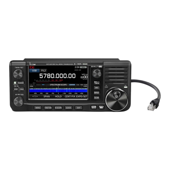
IC-905
Controller and RF unit
IC-905
(Controller)
(5 m: 16.4 feet)
(RF unit)
DC power cable
Ferrite EMI filter
(1.5 m: 4.9 ft)
Icom and the Icom logo are registered trademarks of Icom Incorporated (Japan) in Japan, the United States, the United Kingdom, Germany,
France, Spain, Russia, Australia, New Zealand, and/or other countries.
Thank you for choosing this Icom product.
READ ALL INSTRUCTIONS carefully and completely
before using this product.
BE CAREFUL! When you install the IC-905's RF unit and
antenna, wear gloves to avoid cutting your hand on the
sharp edges of the metal parts or antenna.
Icom is not responsible for any building breakage, any
damage resulting from a drop of the mounting bracket from
a high place or unstable site, or any personal injury or any
accident in any other case. Be sure to consult an expert
engineer for installation help.
GPS antenna
Assembled screws
Bracket
for bracket
(6 × 15 mm)
Screws and washers
Rubber
Pole clamps
U-bolts
for attaching to a pole
vulcanizing tape
– 1 –
Advertisement
Table of Contents

Subscribe to Our Youtube Channel
Related Manuals for Icom IC-905


Summary of Contents for Icom IC-905
- Page 1 – 4 – Icom and the Icom logo are registered trademarks of Icom Incorporated (Japan) in Japan, the United States, the United Kingdom, Germany, 1-1-32 Kamiminami, Hirano-ku, Osaka 547-0003, Japan France, Spain, Russia, Australia, New Zealand, and/or other countries.
- Page 2 40 ~ 60 mm Torque: 5 N•m the GPS satellites. RF unit LThe IC-905 automatically adjusts the internal reference (Approximately 3.2 kg, 7.1 lb) frequency using the received GPS data as the default setting. NOTE: • Make the connection as short as possible.
Need help?
Do you have a question about the IC-905 and is the answer not in the manual?
Questions and answers