Bender COMTRAXX CP9 Series Manual
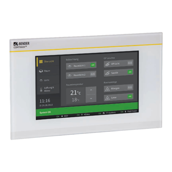
Remote alarm indicator and operator panel for medical locations and other areas
Hide thumbs
Also See for COMTRAXX CP9 Series:
- Manual (44 pages) ,
- Quick start manual (9 pages) ,
- Quick start manual (8 pages)

Related Manuals for Bender COMTRAXX CP9 Series


Summary of Contents for Bender COMTRAXX CP9 Series
- Page 1 COMTRAXX® CP9xx – Control Panel Remote alarm indicator and operator panel for medical locations and other areas Software version V4.6.x CP9xx_D00349_09_M_XXEN/03.2023 Manual EN...
- Page 2 CP9xx_D00349_09_M_XXEN/03.2023...
-
Page 3: Table Of Contents
Signs and symbols............................5 Service and Support............................5 Training courses and seminars........................ 5 Delivery conditions............................6 Inspection, transport and storage......................6 Warranty and liability..........................6 Disposal of Bender devices........................6 1.10 Safety................................. 7 Intended use..................... 8 Product description..................9 Scope of delivery............................9 Device features.............................. 9 Possible applications..........................10... - Page 4 Table of contents Data modules...............................27 Example of a data query......................... 29 Modbus TCP server..................30 Troubleshooting..................... 31 Malfunctions..............................31 6.1.1 What should be checked?........................31 6.1.2 Frequently asked questions........................31 Device operation, maintenance, cleaning..................31 Technical data....................32 Tabular data..............................32 Standards, approvals and certi cations.....................40 Ordering information CP9xx........................
-
Page 5: General Instructions
Recycling RoHS directives Service and Support Information and contact details about customer service, repair service or eld service for Bender devices are available on the following webside: Fast assistance | Bender GmbH & Co. KG. Training courses and seminars Regular face-to-face or online seminars for customers and other interested parties: www.bender.de >... -
Page 6: Delivery Conditions
General instructions Delivery conditions The conditions of sale and delivery set out by Bender GmbH & Co. KG apply. These can be obtained in printed or electronic format. The following applies to software products: ‘Software clause in respect of the licensing of standard software as part of deliveries,... -
Page 7: Safety
COMTRAXX® CP9xx – Control Panel 1.10 Safety If the device is used outside the Federal Republic of Germany, the applicable local standards and regulations must be complied with. In Europe, the European standard EN 50110 applies. DANGER Risk of fatal injury due to electric shock! Touching live parts of the system carries the risk of: •... -
Page 8: Intended Use
These include, for example: • All Bender devices with BMS bus or BCOM interface • Bender devices (PEM, energy meters,…) with Modbus RTU or Modbus TCP interface • Other devices with Modbus RTU or Modbus TCP interface In addition, the data is available via the Modbus TCP protocol. This allows coupling to a higher-level building control system as well as visualisation and evaluation using standard web browsers. -
Page 9: Product Description
Included within the scope of delivery • A CP9xx alarm indicator and operator panel • A printed quick-start guide • Safety instructions for Bender products • The manuals ‘COMTRAXX® CP9xx’ and ‘BCOM’ are available as PDF les for download at https:// www.bender.de/en/service-support/download-area/ For CP915 and CP924 additionally •... -
Page 10: Possible Applications
Product description Possible applications Monitoring, operation and display of • Medical IT systems • Supply systems for medical gases • HVAC systems • Room lighting • Operating theatre lights • Special power supply systems (BSV or UPS) • Other systems from di erent manufacturers Con guration, diagnosis, service Each panel can be individually manufactured and tailored to the requirements of the user. -
Page 11: Applications
The devices can only be operated on the internal BMS bus. • BCOM (Ethernet) for new and future Bender systems, such as ISOMETER® iso685-D. • Modbus RTU (RS-485) CP9xx when operated as a master for Bender devices PEM… with restricted functionality (full functionality of PEM…5 only via Modbus TCP). -
Page 12: Process Image
Product description Image 3-1: System overview interfaces CPxx 3.8.2 Process image The CP9xx alarm indicator and operator panel combines the information from the di erent interfaces and makes it available for operation and visualisation via the web user interface of a PC. It acts as a central user interface. -
Page 13: Mounting
COMTRAXX® CP9xx – Control Panel Only quali ed personnel are permitted to carry out the work necessary to install, commission and run a device or system. CAUTION Functional earth The device must be earthed. Without connection of the functional earth, the device function is not guaranteed. - Page 14 Dimension diagram Device dimensions Dimensions (mm) ±1 Type CP907 176 (7‘) CP915 386 (15,6‘) COMTR X® CP924 610 (24‘) Installation dimensions enclosure Dimensions (mm) Required Type Enclosure installation depth Flush- mounting CP907 Surface- Glass thickness: 3 mm mounting Flush- CP915 mounting Flush- CP924...
- Page 15 COMTRAXX® CP9xx – Control Panel For surface mounting, the ush-mounting enclosure is mounted in the optionally available surface-mounting enclosure (B95061915). Enclosure for surface mounting CP907, dimensions in mm Mounting procedure: Assemble surface-mounting enclosure ( t hinges and bracket). Insert the ush-mounting enclosure through the opening in the cover. Mount the enclosed plastic frame from behind and screw it in place using the fasteners of the ush-mounting enclosure.
- Page 16 Removing the CP915/CP924 front plate The front plate is removed from the enclosures of the CP915 and CP924 devices using a suction lifter. For this purpose, the suction lifter must be placed on the points marked below one after the other and the front plate must be removed until it clicks into place for the rst time.
- Page 17 COMTRAXX® CP9xx – Control Panel Remove the CP9xx from the built-in ush-mounting enclosure. Mainboard and connections of the CP9xx device Connection CP907 CP915/CP924 Plug connector digital inputs I²C interface Plug connector to energy storage board Voltage supply A1/+, A2/–, PE Ethernet (RJ45/CAT5);...
- Page 18 If the CP9xx is located at the beginning or end of the respective bus (Modbus RTU and BMS), the respective terminating switch of the device (7) must be switched to ‘ON’ . Establish connection with PC and BCOM: Connect the CP9xx device to the PC network using an Ethernet cable (5).
- Page 19 COMTRAXX® CP9xx – Control Panel Connect terminals A1/+ and A2/- (4) to the power source. Connect PE to earth. The CP907-I can also be supplied via Power-over-Ethernet (PoE). The PoE switch must be earthed. For further details, see technical data. Attach the front plate to the built-in ush-mounting enclosure.
- Page 20 The dual power supply unit supplies the CP915 or CP924 with 24 V and the display with 12 V. 13. CP915: Attach the front plate to the built-in ush-mounting enclosure. 14. CP924: Hold the display unit from above in front of the ush-mounting enclosure. Place the two mounting hooks behind the upper snap locks of the ush-mounting enclosure (see red markings).
-
Page 21: Digital Inputs
COMTRAXX® CP9xx – Control Panel Digital inputs CP9xx-devices feature 12 con gurable digital inputs. Settings are made via the COMTRAXX® user interface in a browser. Function The following functions can be assigned to the digital inputs: Digital input without function TEST Self test of the device RESET... -
Page 22: Relay
Relay Connection relay N/C operation contacts 11-12 (the alarm relay is energised during normal operation). N/O operation contacts 11-14 (the alarm relay is de-energised during normal operation). Commissioning of the CP9xx device Switch on the supply voltage: After switching on, the device performs a start routine. It is completed when the commissioning page appears on the display. - Page 23 These commands can be copied to the clipboard of the PC and then included in the programming of the external application. • Graphical display with scaling of the time axis for the data loggers of the gateway and compatible Bender devices.
-
Page 24: Address Con Guration And Termination
Multiple assignment of addresses The factory setting for the system name on all Bender BCOM devices is ‘SYSTEM’ . If several systems with the same system name are integrated into the same network, addresses are assigned twice. This leads to transmission errors. - Page 25 COMTRAXX® CP9xx – Control Panel COMTRAXX® user interface The device has a web user interface for setting and operation. How to start the web user interface: • Open an Internet browser from any network device. • Enter the address of the CP9xx device in the address line of the browser. It is possible to connect the CP9xx directly to a computer/laptop.
- Page 26 Factory settings of the communication addresses Parameter Factory setting IP address IP address for 1:1 ETH connection 169.254.0.1 Net mask 255.255.0.0 Standard gateway 192.168.0.1 DHCP Timeout for DHCP address assignment 30 s BMS address BMS protocol BMS i BCOM system name SYSTEM Subsystem address BCOM device address...
-
Page 27: Profinet
• Provision of GSDML le The GSDML le is also available in the download area of our homepage at https://www.bender.de/en/service-support/download-area/ Device assignment for PROFINET To make the required measured values or alarm states available via PROFINET, a device assignment must be generated for the PROFINET image. - Page 28 PROFINET Data module Format Comment/Unit Measured value Float32 Measured value of the measuring channel as floating point number (IEEE754) with 32 bits Measuring channel structure UINT32 Time stamp in s as 32-bit unsigned integer (UTC) (Complete measuring channel as UINT16 Decimal places of the time stamp in ms as 16-bit a structure with 26 bytes) unsigned integer...
-
Page 29: Example Of A Data Query
COMTRAXX® CP9xx – Control Panel Example of a data query Example: Query measuring channel of an iso685-D The iso685-D is connected to the COMTRAXX® device via BCOM. Measuring channel 3 (leakage capacitance ) is to be made available on slot 13 in order to be able to read it out via PROFINET. In order for the required measuring channel to be read via PROFINET, it only has to be included in the device assignment. -
Page 30: Modbus Tcp Server
Modbus TCP server Modbus TCP server The Modbus TCP server supports the following function codes: • Function code 0x03 (Read Holding Registers) • Function code 0x04 (Read Input Registers) • Function code 0x10 (Preset Multiple Registers) The Modbus TCP server generates a function-related response to requests and sends it back to the Modbus TCP client. -
Page 31: Troubleshooting
Document the new settings as a PDF le. Use the backup function to save all settings of the device (see Chapter: Device features). Frequently asked questions on the Internet FAQs on many Bender devices can be found at: Fast assistance | Bender GmbH & Co. KG Device operation, maintenance, cleaning Device operation The device can be operated with latex, vinyl and nitrile gloves without impairing functionality. -
Page 32: Technical Data
Technical data Technical data Tabular data Insulation coordination acc. to IEC 60664-1 CP907 Rated voltage 50 V Overvoltage category Pollution degree Rated impulse voltage 800 V CP915 / CP924 Rated voltage AC 250 V Overvoltage category Pollution degree Rated impulse voltage 4 kV Supply CP907 via plug-in terminal (A1/+;... - Page 33 COMTRAXX® CP9xx – Control Panel CP915 via terminal block (L1; N) Nominal voltage via external power supply unit AC 100… 240 V Nominal voltage tolerance -15…+10 % Frequency rangeU 50…60 Hz Typical power consumption at AC 230 V < 30 W CP924 via terminal block (L1;...
- Page 34 Technical data Interfaces Ethernet Connection RJ45 Cable shielded, both ends of shield connected to PE Cable length < 100 m Data rate 10/100 Mbit/s, autodetect HTTP mode HTTP/HTTPS (HTTP)* DHCP on/off (off)* (DHCP) 5…60 s (30 s)* IP address nnn.nnn.nnn.nnn (192.168.0.254)*, always reachable via: 169.254.0.1 Net mask nnn.nnn.nnn.nnn (255.255.0.0)*...
- Page 35 Modbus TCP Interface/protocol Ethernet/Modbus TCP Cable length < 100 m Operating mode client for Bender Modbus TCP devices and ‘third-party devices’ Operating mode Server for access to process image and for Modbus control commands Parallel data access from different clients max.
- Page 36 Technical data Number Operating mode USB-2.0 host (5 V, 500 mA) Data rate 480 Mbit/s Cable length < 3 m Connection type USB 2 Standard-A Used ports DNS (UDP/TCP) 67, 68 DHCP (UDP) HTTP (TCP) NTP (UDP) SNMP (UDP) HTTPS (TCP) MODBUS (TCP) 4840 OPCUA (TCP)
- Page 37 COMTRAXX® CP9xx – Control Panel Switching elements Number 1 relay Operating mode N/C operation or N/O operation Function programmable Electrical endurance under rated operating conditions, 10,000 number of cycles Contact data acc. to IEC 60947-5-1 Utilisation category AC-13 / AC-14 / DC-12 Rated operational voltage 24 V / 24 V / 24 V Rated operational current...
- Page 38 Technical data Plug-in terminal (A1/+; A2/-) (11;12;14) Plug-in terminal (A1/+; A2/-; PE) (11;12;14) Conductor sizes AWG 24-12 Stripping length 10 mm rigid/flexible 0.2…2.5 mm² flexible with ferrule with/without plastic sleeve 0.25…2.5 mm² Multiple conductor, flexible with TWIN ferrule with 0.5…1.5 mm² plastic sleeve Plug-in terminal (l1…12), (k1…k12), (…MB), (…BMS) Conductor sizes...
- Page 39 COMTRAXX® CP9xx – Control Panel Classi cation of climatic conditions acc. to IEC 60721 Stationary use (IEC 60721-3-3) 3K22 Transport (IEC 60721-3-2) 2K11 Long-term storage (IEC 60721-3-1) 1K22 Classi cation of mechanical conditions acc. to IEC 60721 Stationary use (IEC 60721-3-3) CP907 only 3M11 Stationary use (IEC 60721-3-3) CP915 only 3M10...
-
Page 40: Standards, Approvals And Certi Cations
Technical data Standards, approvals and certi cations CP907 only B95061080 Ordering information CP9xx Complete devices Device Display Display dimensions Type Supply Weight (glass Art. No. size (W x H x D), tempered) CP907 1.1 kg white B95061080 DC 24 V, < 15 W 7‘... -
Page 41: Document Revision History
COMTRAXX® CP9xx – Control Panel Accessories Device series Type Art. No. CP907 Surface-mounting enclosure B95061915 CP915, CP924 CP9xx suction lifter B95061911 CP9xx replacement plug kit B95061910 The suction lifter is required to remove the display Document revision history Document Valid from Date State/Changes version... - Page 44 Nachdruck und Vervielfältigung Reprinting and duplicating nur mit Genehmigung des Herausgebers. only with permission of the publisher. Bender GmbH & Co. KG Bender GmbH & Co. KG Postfach 1161 • 35301 Grünberg • Deutschland PO Box 1161 • 35301 Grünberg • Germany Londorfer Str.
Need help?
Do you have a question about the COMTRAXX CP9 Series and is the answer not in the manual?
Questions and answers