Bender COMTRAXX CP9 Series Manual
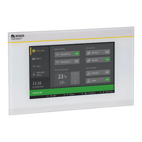
Customised alarm indicator and operator panel for medical locations and other areas
Hide thumbs
Also See for COMTRAXX CP9 Series:
- Manual (44 pages) ,
- Quick start manual (9 pages) ,
- Manual (40 pages)

Related Manuals for Bender COMTRAXX CP9 Series


Summary of Contents for Bender COMTRAXX CP9 Series
- Page 1 COMTRAXX® CP9xx-x – Control Panel Customised alarm indicator and operator panel for medical locations and other areas CP9xx-x_D00406_00_M_XXEN/04.2020 Manual EN...
- Page 2 Service and support for Bender products First-level support Technical support Carl-Benz-Strasse 8 • 35305 Grünberg • Germany Telephone: +49 6401 807-760 0700BenderHelp * Fax: +49 6401 807-629 E-mail: support@bender-service.de Available on 365 days from 7.00 a.m. to 8.00 p.m. (MEZ/UTC +1) * Landline German Telekom: Mon-Fri from 9.00 a.m.
-
Page 3: Table Of Contents
1.2.1 Signs and symbols ......................5 Training courses and seminars.................5 Delivery conditions .......................5 Inspection, transport and storage ................6 Warranty and liability....................6 Disposal of Bender devices ..................6 Safety ..........................7 Product description ................9 Intended use ........................9 Device features ......................10 Applications ......................... 17 Function ......................... - Page 4 CP9xx-x_D00406_00_M_XXEN/04.2020...
-
Page 5: General Instructions
Training courses and seminars www.bender.de -> Know-how -> Seminars. Delivery conditions The conditions of sale and delivery set out by Bender apply. These can be obtained from Bender in printed or electronic format. The following applies to software products: “Software clause in respect of the licensing of standard software as part of de-... -
Page 6: Inspection, Transport And Storage
• Non-observance of technical data. • Repairs carried out incorrectly. • Use of accessories and spare parts not recommended by Bender. • Catastrophes caused by external influences and force majeure. • Mounting and installation with device combinations not recommended by the manufac- turer. -
Page 7: Safety
COMTRAXX® CP9xx-x – Control Panel Safety If the device is used outside the Federal Republic of Germany, the applicable local standards and regulations must be complied with. In Europe, the European standard EN 50110 applies. ! Risk of fatal injury due to electric shock! Touching live parts of the system carries the anger risk of: •... - Page 8 Product description CP9xx-x_D00406_00_M_XXEN/04.2020...
-
Page 9: Product Description
They are used for: • Display and visualisation of operating, warning and alarm messages • Central control and parameter setting of BMS bus devices (BMS = Bender Measuring Device Interface) • Output of visual and acoustic warning messages •... -
Page 10: Device Features
Product description Device features The CP9xx-x series includes the following variants of customised alarm indicator and operator panels: • CP9xx-F (only with front foil) • CP9xx-G (only with glass front plate) • CP9xx-H (with front foil and glass front plate) The following basic types are described in the CP9xx-x series: CP907-F, CP915-F, CP924-F with CP9xx-F alarm indicator and operator panels are equipped... - Page 11 COMTRAXX® CP9xx-x – Control Panel Some implementation examples are given below: Fig. 2–1 CP915-F in bezel frame enclosure with individual, project-specific internal components CP9xx-x_D00406_00_M_XXEN/04.2020...
- Page 12 Product description Fig. 2–2 CP921-F in bezel frame enclosure with individual, project-specific internal components CP9xx-x_D00406_00_M_XXEN/04.2020...
- Page 13 COMTRAXX® CP9xx-x – Control Panel Fig. 2–3 CP921-F with two front plates in bezel frame enclosure. Lower front plate with individual, project-specific internal components CP9xx-x_D00406_00_M_XXEN/04.2020...
- Page 14 Product description Fig. 2–4 CP924-F with two front plates in bezel frame enclosure. Right front plate with individual, project-specific internal components Fig. 2–5 CP915-F with mounting frame with individual, project-specific internal components CP9xx-x_D00406_00_M_XXEN/04.2020...
- Page 15 COMTRAXX® CP9xx-x – Control Panel Fig. 2–6 CP924-F with two front plates in bezel frame enclosure (including examples of customised indi- vidual internal components) Fig. 2–7 CP924-H with two front plates in bezel frame enclosure, upper front plate glass, lower front plate with foil front (including examples of customised individual internal components) CP9xx-x_D00406_00_M_XXEN/04.2020...
- Page 16 Product description Fig. 2–8 CP924-F with two front plates in bezel frame enclosure (irongrey, including examples of custom- ised individual internal components) Fig. 2–9 CP924-H with two front plates in bezel frame enclosure Left front plate glass, right front plate foil front and individual, project-specific internal components CP9xx-x_D00406_00_M_XXEN/04.2020...
-
Page 17: Applications
PCs, if required. Contact your IT administrators in this regard. After connection to the network and compatible Bender products, all system devices can be accessed from any PC via a web browser. In this way, all important system information is directly available. -
Page 18: Software Products Used
Multiple assignment of addresses The default system name on all Bender BCOM devices is "SYSTEM". If several systems with the same system name are integrated into the same network, addresses are assigned twice. This leads to transmission errors. Always enter a unique BCOM system name during initial setup. -
Page 19: Mounting And Connection
COMTRAXX® CP9xx-x – Control Panel Mounting and connection Mechanical installation 3.1.1 General description The mechanical design of the enclosure for flush mounting with bezel frame is oriented toward longevity and particularly suited for the high hygienic requirements in medical locations. The en- closures are all custom made to suite the technical and mechanical requirements on site. -
Page 20: Opening And Closing The Front Plate
Mounting and connection 3.1.2 Opening and closing the front plate According to the subsequent standards, the enclosure may only be opened using keys or tools (e.g. a suction lifter): • VDE 0660-600-1, -2, chap. 8.4.2.3 • IEC/EN 61439-1, -2, chap. 8.4.2.3 Each alarm indicator and operator panel is supplied with a suction lifter, which is normally at- tached to the cable harness. - Page 21 COMTRAXX® CP9xx-x – Control Panel ! Damage/Failure due to fluid ingress! aution If the seal of the front plate is not positioned evenly in the bezel frame, cleaning fluids may en- ter the alarm indicator and operator panel, damage the electronics and thereby cause a failure of the panel.
-
Page 22: Removing The Front Plate Of Cp915 And Cp924
Mounting and connection 3.1.3 Removing the front plate of CP915 and CP924 The front plate is removed from the enclosure of the CP915 and CP924 alarm indicator and opera- tor panel by means of a suction lifter. For this purpose, the tool must be placed at the points marked below and the front plate must be removed until it clicks into place for the first time. -
Page 23: Mounting Instructions
COMTRAXX® CP9xx-x – Control Panel Mounting instructions Important mounting instructions: • The enclosure must be mounted on an even surface! • The enclosure must not warp during mounting! • Make sure that the enclosure is mounted at right angles! • It is recommended to make the wall cutout 3 mm larger than the flush-mounting enclo- sure! For installation of the flush-mounting enclosure with bezel frame refer to illustration # 9800267- 01_00 on the subsequent page. -
Page 24: Mounting A Flush-Mounting Enclosure With Bezel Frame Enclosure
Mounting and connection 3.2.1 Mounting a flush-mounting enclosure with bezel frame enclosure Fig. 3–1 Illustration No. 9800267-01_00 CP9xx-x_D00406_00_M_XXEN/04.2020... -
Page 25: Cross Section View Flush-Mounting Enclosure With Bezel Frame
COMTRAXX® CP9xx-x – Control Panel 3.2.2 Cross section view flush-mounting enclosure with bezel frame Fig. 3–1 Illustration No. 9800269-01_00 CP9xx-x_D00406_00_M_XXEN/04.2020... -
Page 26: Cross Section View Flush-Mounting Enclosure With Bezel Frame For Cavity Wall Mounting
Mounting and connection 3.2.3 Cross section view flush-mounting enclosure with bezel frame for cavity wall mounting Fig. 3–1 Illustration No. 9800270-01_00 CP9xx-x_D00406_00_M_XXEN/04.2020... -
Page 27: Fastening, Cable Entry
COMTRAXX® CP9xx-x – Control Panel Fastening, cable entry 3.3.1 Fastening Please observe illustration # 9800373-01_00 on the subsequent page. • Fastening holes can be drilled into the plastic side pieces of the enclosure (see hatch- ing). From the enclosure bottom in the area between 8 mm and the calculated value fas- tening T or from the finished wall surface at a depth greater than 62 mm (see cross sec- tion illustration). - Page 28 Mounting and connection Mounting and fastening of flush-mounting enclosure with bezel frames 20.0 20.0 13.0 13.0 30.0 Fig. 3–1 Illustration No. 9800373-01_00 CP9xx-x_D00406_00_M_XXEN/04.2020...
-
Page 29: Electrical Connection
• To comply with the EMC requirements the wiring and installation instructions in the en- closed documentation has to be followed, especially those of manufacturers other than Bender. • The internal wiring and the installation has been made in accordance with the specifica- tions of the components manufacturer. - Page 30 Important information CP9xx-x_D00406_00_M_XXEN/04.2020...
-
Page 31: Important Information
CP9xx-x alarm indicator and operator panels. For further information, refer to: Web user interface for Bender Condition Monitors COM465IP, COM465DP and CP907-I as well as the "COMTRAXX®" (D00135) manuals. The I/O control unit might be external and is always individually equipped. The actual design is shown in the individual, project-related circuit diagram. - Page 32 Technical data CP9xx-x_D00406_00_M_XXEN/04.2020...
-
Page 33: Technical Data
COMTRAXX® CP9xx-x – Control Panel Technical data Supply voltage Supply voltage ................................AC 230 V Frequency range ................................50…60 Hz Internal supply ................................DC 12/24 V Power consumption .................................< 55 VA Touch Monitor Size Resolution 24"/16:9 1920x1080 21.5"/16:9 1920x1080 15.6"/16:9 1366x768 Background lighting ........................top/bottom edge side LED type Amount colours ................................. - Page 34 Technical data CP9xx-x_D00406_00_M_XXEN/04.2020...
- Page 35 COMTRAXX® CP9xx-x – Control Panel CP9xx-x_D00406_00_M_XXEN/04.2020...
- Page 36 Nachdruck und Vervielfältigung Reprinting and duplicating nur mit Genehmigung des Herausgebers. only with permission of the publisher. Bender GmbH & Co. KG Bender GmbH & Co. KG Postfach 1161 • 35301 Grünberg • Deutschland PO Box 1161 • 35301 Grünberg • Germany Londorfer Str.
Need help?
Do you have a question about the COMTRAXX CP9 Series and is the answer not in the manual?
Questions and answers