Bender COMTRAXX CP305 Manual
Remote alarm indicator for medical locations and other areas
Hide thumbs
Also See for COMTRAXX CP305:
- Manual (68 pages) ,
- Quick start manual (9 pages) ,
- Quick start manual (8 pages)

Subscribe to Our Youtube Channel
Related Manuals for Bender COMTRAXX CP305


Summary of Contents for Bender COMTRAXX CP305
- Page 1 COMTRAXX® CP305 - Control Panel Remote alarm indicator for medical locations and other areas CP305_D00425_00_M_XXEN_09.2022 Manual EN...
- Page 2 Kundendienst / Field Service Vor-Ort-Service Telefon: +49 6401 807-752, -762 (technisch) oder +49 6401 807-753 (kaufmännisch) Fax: +49 6401 807-759 E-Mail: eldservice@bender-service.de Mo-Do 07:00 - 16:00 Uhr, Fr 07:00 - 13:00 Uhr (MEZ/UTC +1) Table: Service und Support für Bender-Produkte CP305_D00425_00_M_XXEN_09.2022...
-
Page 3: Table Of Contents
Indication of important instructions and information..............6 1.2.1 Signs and symbols............................6 Training courses and seminars........................ 7 Delivery conditions............................7 Inspection, transport and storage......................7 Warranty and liability..........................7 Disposal of Bender devices........................8 Safety................................. 8 Intended use..................... 9 Product description..................10 Scope of delivery............................10 Device features............................10 System description............................ 12 Interfaces............................... - Page 4 Table of contents Factory settings for communication.............30 Display and operation................... 31 Display CP305: Menu structure..............33 10.1 Measured values............................33 10.2 Bus overview..............................33 10.3 History................................33 10.4 Alarm and test............................. 35 10.5 Settings................................36 10.6 Info................................... 40 Web user interface: menu structure (via ETH socket)......... 41 11.1 COMTRAXX ®...
- Page 5 COMTRAXX® CP305 - Control Panel 12.6 Clock................................53 12.7 Display................................53 12.8 Security................................53 12.9 Buzzer................................54 12.10 Service inspection............................54 12.11 Factory setting.............................55 Web user interface: Menu structure (access via gateway)......56 13.1 Device tools..............................56 13.2 Menu................................57 13.2.1 Edit texts................................ 57 13.2.2 Info...................................
-
Page 6: General Instructions
This manual is intended for quali ed personnel working in electrical engineering and electronics! Part of the device documentation in addition to this manual is the enclosed supplement " Safety instructions for Bender products". Read the operating manual before mounting, connecting and commissioning the device. -
Page 7: Training Courses And Seminars
Regular face-to-face or online seminars for customers and other interested parties: www.bender.de -> Fachwissen -> Seminare. Delivery conditions The conditions of sale and delivery set out by Bender GmbH & Co. KG apply. These can be obtained in printed or electronic format. The following applies to software products: "Softwareklausel zur Überlassung von Standard- Software als Teil von Lieferungen,... -
Page 8: Disposal Of Bender Devices
Disposal of Bender devices Abide by the national regulations and laws governing the disposal of this device. For more information on the disposal of Bender devices, refer to www.bender.de -> Service & Support. Safety If the device is used outside the Federal Republic of Germany, the applicable local standards and regulations must be complied with. -
Page 9: Intended Use
COMTRAXX® CP305 - Control Panel Intended use Remote alarm indicator COMTRAXX ® CP305 is used for visual and audible signalling of operating and alarm messages from the Bender systems MEDICS ® , ATICS ® , EDS and RCMS. In MEDICS ®... -
Page 10: Product Description
• Additionally for CP305-IO: connections for the digital inputs and relay contacts • A printed quick reference guide (the manuals are available at: www.bender.de > Service & Support > Download area > Operating manual) • Safety instructions for Bender products Versions •... - Page 11 • History memory with real-time clock to store 1000 warnings and alarms • Power supply via power supply unit • Parameter setting via Ethernet interface • NFC interface for connection to the Bender Connect app • Replacing MK2430 (retro t); other devices on request Additionally CP305-IO •...
-
Page 12: System Description
Product description Applications • Visualisation on the display optimally tailored to the user • Integration of all compatible Bender products (MEDICS ® , ATICS ® , EDS, Linetraxx ® RCMS systems and ISOMETER ® • Individual instructions for action in the event of alarms... -
Page 13: Interfaces
Connection example BMS and Ethernet In the example, the ICU can be monitored from the station base. In addition, remote maintenance is possible via the building services or Bender. Interfaces The BMS bus is used for communication with BMS bus nodes or devices like RCMS…, EDS…, SMI…, SMO…, ATICS... - Page 14 The powered device can also have its parameters set via NFC. The interface is activated on the CP305 under > Settings > Interface > NFC. Afterwards, the prepared con guration can be loaded onto the device using the Bender Connect app. CP305_D00425_00_M_XXEN_09.2022...
-
Page 15: Mounting
COMTRAXX® CP305 - Control Panel Mounting Dimension diagram CP305 All dimensions are in mm. Flush-mounting The ush-mounting enclosure is optionally available (B923710). CP305_D00425_00_M_XXEN_09.2022... - Page 16 Mounting Dimension diagram ush-mounting enclosure All dimensions are in mm. CP305_D00425_00_M_XXEN_09.2022...
- Page 17 COMTRAXX® CP305 - Control Panel Installation of ush-mounting enclosure Insert the supplied cardboard into the ush-mounting enclosure to provide protection against pollution. Insert the enclosure so that it is ush with the wall surface. The ush-mounting enclosure must not be installed lopsidedly or warped, and must not be installed too deep below the surface.
-
Page 18: Surface Mounting
Mounting Surface mounting For surface mounting, the matching surface-mounting enclosure (item no. B95100153) must be used. All dimensions are in mm. 100.5 185.5 CP305_D00425_00_M_XXEN_09.2022... -
Page 19: Retro T: Replacement Of Mk2430
In the context of retro t measures, CP305 can be installed directly in the existing ush-mounting MK2430 enclosures. If MK2418, MK2410 or other devices are to be replaced, the ush-mounting enclosures must be changed. Please contact Bender Service for details. CP305_D00425_00_M_XXEN_09.2022... -
Page 20: Connection
Connection Connection Safety instructions Only skilled persons are permitted to carry out the work necessary to install, put into service and run a device or system. Danger of electric shock! DANGER Follow the basic safety rules when working with electricity. Observe the information on rated voltage and supply voltage speci ed in the technical data! DANGER Connect the CP305 exclusively according to the connection diagram in this chapter. - Page 21 COMTRAXX® CP305 - Control Panel PELV If a DC power supply unit is used to supply one or more CP305 devices, A2/- can be connected to protective earth. Then shielded Ethernet cables can also be used. SELV If an AC or DC power supply without a secondary connection between A2/- and protective earth is used to supply one or more CP305 devices, unshielded Ethernet cables must be used.
-
Page 22: Connection Diagram
Connection Connection diagram GND 1-4 K2 NO IN 1 K2 NC IN 2 K2 COM IN 3 IN 4 K1 NO GND 5-8 K1 NC IN 5 K1 COM CP305-IO IN 6 BMS A IN 7 BMS B IN 8 Term = on A1/+ GND 9-12... - Page 23 IN1 to 12. Ethernet interface for connection of a PC The CP305 can be integrated into the Bender/hospital network via the Ethernet interface. Parameters can be set on the PC, and data as well as the history memory can be read out.
- Page 24 Alternatively Cable, twisted pairs, J-Y(St)Y min. 2x0.8 Connect shield to PE on one side Various Bender devices with a BMS bus interface. Examples: ATICS, ISOMED427P, EDS151, RCMS…, CP9xx, … * Devices without BMS bus connection, but with test input (e.g ISOMETER ®...
-
Page 25: Ethernet Connection
COMTRAXX® CP305 - Control Panel Ethernet connection An RJ45 socket insert and a Cat.6 SLIM patch cable are included in the connector kit (item no. B95100152). The CP305 cannot be connected with a standard RJ45 cable with a rigid connector without the connector kit. - Page 26 Connection Response times t The response time t after a switch-on signal can be adjusted from 100 ms … 10 minuts The response time t after a switch-on signal can be adjusted from 100 ms … 10 minuts Relay CP305-IO has 2 relay outputs (changeover contacts K1 and K2) for which parameters can be set. They can be used to forward error, test or (collective) alarm messages to a building management system.
-
Page 27: Commissioning
COMTRAXX® CP305 - Control Panel Commissioning Commissioning assistant During initial putting into service or after a reset to factory settings, the putting-into-service wizard opens for the basic setup steps. The putting-into-service wizard launches in English. The header is blue, and the LED is green. You need to log in to the device (with the PIN via the icon in the header). - Page 28 Appstores for and Android. In the Bender Connect app the device rst needs to be made known. Then the device-speci c setting options are shown so that they can be con gured. When the data is transferred, feedback is given whether the parameter con guration has been successful.
-
Page 29: Software Update
It is recommended to create a backup before an update. Download the current software version from the Bender homepage and save it to your PC. Now connect the CP305 to the PC. -
Page 30: Factory Settings For Communication
Factory settings for communication Factory settings for communication The settings can be changed on the device or via the web user interface. Parameter Parameter IP address IP address for 1:1 ETH connection Address range (169.254.xx.yy) Note: xx and yy are derived from the MAC address during putting into service and are therefore unique for each CP305. -
Page 31: Display And Operation
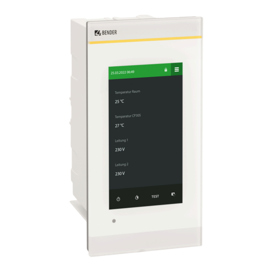
COMTRAXX® CP305 - Control Panel Display and operation LED and display Display in normal operation: There are no warnings or alarms pending. • The LED lights up green. • The display shows the programmed default display screen (start page). You set parameters for the start page in the web operating application. Display when warning or alarm messages are pending •... - Page 32 Display and operation Timer active Device muted Footer Timer • Setting range: 1 s to (10 h - 1 s) Resolution of setting 1 s • A timer can be set and started on the default display screen. It counts down to 0 and signals the elapsed time interval with its buzzer.
-
Page 33: Display Cp305: Menu Structure
COMTRAXX® CP305 - Control Panel Display CP305: Menu structure Normal state: The header and the LED are green when there is no alarm. In the event of an alarm, the header and LED take on the colour of the highest alarm level present. - Page 34 Display CP305: Menu structure Detail pop-up of an entry in the history Element Comments Messages that come up are indicated in di erent colours, depending on their type, both on the display and in the stored history. Error category Warnings: yellow Alarms: red Warning end, alarm end: green Device error...
-
Page 35: Alarm And Test
COMTRAXX® CP305 - Control Panel Element Comments Number of the error message in the history Path speci cation Address where the error occurred Type Alarm start, alarm end, error, device restart Time stamp Occurrence and end of the error 10.4 Alarm and test Alarm addresses Display of the addresses/measuring channels whose alarm messages are assigned to the CP305. -
Page 36: Settings
Display CP305: Menu structure 10.5 Settings The settings of the CP305 are displayed here. You can adjust some device settings directly on the device if you log in. Changed settings are highlighted in yellow. The changes are con rmed (green tick) or discarded (red X) in the header. - Page 37 COMTRAXX® CP305 - Control Panel Interface You can enter the settings for the various interfaces here. The current parameter settings are displayed. Ethernet DHCP (on, o ); IP address (DHCP) Manual: assign an IP address for the local network The automatically assigned IP address for a 1:1 connection cannot be changed.
- Page 38 Display CP305: Menu structure Display General • Language • Alignment • Cleaning mode active Setting option: deactivated or locked for 5…20 s Alarm messages • Set the time until the page is changed for several pending alarms. Setting range: 3/5/10 seconds Standby mode •...
- Page 39 COMTRAXX® CP305 - Control Panel Server • Administrator User name (display only) Status (enabled, disabled) Password (only *** is shown) Read access (allow) Write access (allow) • User User name (display only) Status (enabled, disabled) Password (only *** is shown) Read access (allow) Write access (deny) •...
-
Page 40: Info
Display CP305: Menu structure Last service Date display on which date the last service check was carried out. Service inspection The service inspection is started here. For the service inspection, it is necessary to rst create at least one alarm address. Factory setting Restart device (Execute) The device can be reset with or without interface settings. -
Page 41: Web User Interface: Menu Structure (Via Eth Socket)
COMTRAXX® CP305 - Control Panel Web user interface: menu structure (via ETH socket) This chapter describes how to access the device through the IP address set for it. You will nd it in the device menu > Info. If you want to access the CP305 through a gateway, there is a limited range of functions when doing so. -
Page 42: Comtraxx User Interface
Language selection Open/close the navigation (button only available with small browser window) If you have forgotten the password, the Bender service can generate a one-time password. Have your serial number ready for this. 11.1.2 Navigation Menu... -
Page 43: Subnavigation
COMTRAXX® CP305 - Control Panel The navigation icons are visible on the left edge at all times. Even if you have just opened any other submenu of the web user interface, you can jump directly to one of the four sections by clicking the desired icon. -
Page 44: Start
Web user interface: menu structure (via ETH socket) 11.2 Start Display of device info (device version, current software, serial number, order number, BCOM name) 11.3 System overview > System Overview > System With direct access via the ETH socket, the “System” is the CP305 itself. When you click the device “CP305”, the following opens in the subnavigation: •... -
Page 45: Menu
COMTRAXX® CP305 - Control Panel Export backup The following data is part of a backup: - Menu parameters - Individual texts relating to the device - For devices of the COMTRAXX series, all relevant con guration les continue to be integrated For security reasons, passwords are not part of a backup. -
Page 46: Bms
Web user interface: menu structure (via ETH socket) 11.3.3 BMS The content section shows the connected BMS bus of the CP305. Clicking a device will cause the current measured values or alarms to be displayed. 11.4 Alarm overview (footer) Overview of pending alarms Click the alarm overview: List of pending alarms Click the list: Details of the alarms in the content section History memory of the device... - Page 47 COMTRAXX® CP305 - Control Panel Alarm addresses Alarm groups tab The alarm groups are created here rst. Alarm addresses can then be assigned to them. Alarm addresses tab Alarms are de ned here and con gured as they are to be displayed. Each measuring channel can be selected as an alarm address and individually con gured, such as the colour of the alarm pop- up, the help texts, the sounds, and so on.
-
Page 48: Device Management
Web user interface: menu structure (via ETH socket) Test addresses Test addresses Display the bus addresses that are to carry out a test when the “TEST” button is pressed on the device display. All test addresses are consolidated into one test group. ®... -
Page 49: Service
Important note: Search for a device can brie y cause considerable data tra c on the network. Log les Log les are saved as txt les. In the event of a fault, log les help Bender Service to more easily nd the cause. Device restart The CP305 can be restarted from the web user interface without it being necessary to disconnect the CP305 from the power supply. -
Page 50: Web User Interface: Settings (Via Eth Socket)
Web user interface: Settings (via ETH socket) Web user interface: Settings (via ETH socket) You need to save the changes before you quit the respective screen. Otherwise, the changes will be discarded. 12.1 Digital inputs 1-12 (CP305-IO only) Menu > Settings > Digital Input 1 - 12 For each of the 12 digital inputs IN1…12 can be set: Parameter Selection/... -
Page 51: Relay 1-2 (Cp305-Io Only)
COMTRAXX® CP305 - Control Panel 12.2 Relay 1-2 (CP305-IO only) Menu > Settings > Relay Carry out operating principle and function for relays 1…2. Operating principle Function Alarm addresses Buzzer Normally open / Normally closed Alarm addresses | Buzzer Test Isometer •... -
Page 52: Individual Texts
Web user interface: Settings (via ETH socket) Active (o , 1 h, 12 h) If NFC is activated, the time of automatic deactivation is shown. If the NFC interface is activated, this is indicated on the device with in the header. 12.4 Individual texts The individual texts assigned here are displayed on the CP305 but cannot be adjusted there. -
Page 53: Clock
COMTRAXX® CP305 - Control Panel 12.6 Clock Setting option for • Time, date, time zone, daylight saving time • Synchronisation with time server (SNTP) (auto DHCP, on, o ) 12.7 Display General • Language • Alignment • Cleaning mode active Setting option: deactivated or locked for 5…20 s Alarm messages •... -
Page 54: Buzzer
Web user interface: Settings (via ETH socket) Server The password for the web user interface is alphanumeric. The factory setting is "admin". • Administrator (user name admin) Status (enabled/disabled) Password (only *** is displayed) Username (display only) Write access (display only) Read access (display only) •... -
Page 55: Factory Setting
COMTRAXX® CP305 - Control Panel Next service (display only) Service inspection Next service Only displayed when a service interval is set. Last service Date display on which date the last service check was carried out. Service inspection The service inspection is started here. For the service inspection, it is necessary to rst create at least one alarm address. -
Page 56: Web User Interface: Menu Structure (Access Via Gateway)
Web user interface: Menu structure (access via gateway) Web user interface: Menu structure (access via gateway) If the CP305 is connected to a CP9xx control panel or a COM465 gateway or the like, a device menu of the CP305 can be opened. This can be used to call up device information. 13.1 Device tools Device tools... -
Page 57: Menu
COMTRAXX® CP305 - Control Panel 13.2 Menu 13.2.1 Edit texts You need to be logged in to the device to create and change individual texts. Changes are saved or discarded in the footer. Device This de nes how the device is designated in the system. •... -
Page 58: Export And Import Of Device Data
Export and import of device data Export and import of device data Di erent device data can be exported via the web user interface. They are exported in the appropriate format depending on the application. You will nd the les in the Download folder of your computer. Likewise, these les can also be imported back into the CP305 (except pdf ). -
Page 59: Cleaning, Servicing And Troubleshooting
COMTRAXX® CP305 - Control Panel Cleaning, servicing and troubleshooting 15.1 Cleaning The glass front can be wiped clean with common cleaning agents. The glass and seal are resistant to alcohol-based disinfectants. 15.2 Servicing The device does not contain any parts that require servicing. Despite this, the intervals speci ed for periodic veri cation should be adhered to. -
Page 60: Malfunctions
(does not match pre-assignment). Incorrect setting “neutral/medical”. 15.6 Recurring inspections The following periodic veri cation must be performed on electrical installations in compliance with the local or national regulations that apply. For your Bender products, we recommend: Action Carried Interval out by Functional test of the IT system monitoring (insulation, load Med. - Page 61 Every 12 skilled months person Test the changeover device, the IT system monitoring, and the Bender Every 24 connection to the SCADA system (Supervisory Control and Data months Acquisition) (if applicable) as well as the interaction between the components in the system.
-
Page 62: Technical Data
Technical data Technical data The CP305 is intended for use in basic (DIN EN 61326-1, Table 1) and industrial (DIN EN 61326-1, Table 2) electromagnetic environments. 16.1 Tabular data ()* = factory setting Insulation coordination CP305 acc. to IEC 60664-1 Rated voltage 50 V Overvoltage category... - Page 63 COMTRAXX® CP305 - Control Panel Stored energy time in the event of voltage failure Time, date Min. 2 days Restart after power failure Min. 2 seconds Displays, memory Display 5" TFT touch display (720 x 1280 px) Displayable devices Number of alarm addresses Number of test addresses Number of history memory entries 1000...
- Page 64 Technical data BMS bus Interface/protocol RS485/BMS internal Operating mode Master/slave (master)* Baud rate 9.6 kBit/s Cable length < 1200 m Shielded cable, one end of shield connected Recommended: CAT6/CAT7 min. AWG23 to PE Alternative: J-Y(St)Y min. 2 x 0.8 Galvanic separation Connection “BMS A”, “BMS B”...
- Page 65 COMTRAXX® CP305 - Control Panel Digital inputs (1…12) (CP305-IO only) Maximum cable length < 500 m Switching elements (CP305-IO only) Plug-in terminal K1 NC; K1 NO; K1 COM Connection K2 NC; K2 NO; K2 COM Number of changeover contacts Operating principle (changeover contacts) N/C operation / N/O operation Function Programmable...
- Page 66 Technical data Device connections Plug-in terminal (A1/+, A2/-) Conductor sizes AWG 24…12 Stripping length 10 mm Rigid/ exible 0.2…2.5 mm² Flexible with ferrules, with/without plastic 0.25…2.5 mm² sleeve Multiple conductor exible with TWIN ferrule 0.5… 1.5 mm² with plastic sleeve Plug-in terminal (BMS A, BMS B) CP305-IO only: (IN1…4, GND1…4, IN9…12, GND9…12) (IN5…8, GND5…8, K1…, K2…)
- Page 67 COMTRAXX® CP305 - Control Panel Environment/EMC IEC 61000-6-2:2016-08 Ed. 3.0 IEC 61000-6-3:2020-07 Ed. 3.0 IEC 61326-1:2020-10 Ed. 3.0 DIN EN 61326-1:2020-10 Ed. 3.0 DIN EN 61326-1:2013-07 DIN EN 50364:2019-05 EN 300 330 V2.1.1 ETSI EN 301 489-3 V2.3.0 Operating temperature -10…+55 °C Operating temperature for UL applications -10…+40 °C...
-
Page 68: Standards And Approvals
Technical data Other Degree of protection of front glass pane IP66 Degree of protection of front for UL IP50 applications Degree of protection of enclosure IP20 Flammability class UL 94V-0 Device dimensions (W x D x H) 181 x 96 x 37.31 mm Weight <... - Page 69 COMTRAXX® CP305 - Control Panel Accessories Type Description Art.-No. Flush-mounting enclosure B923710 Cavity wall installation set for Installation set for ush- B923711 ush-mounting enclosure mounting enclosure B923710 CP305 surface-mounting B95100153 enclosure CP305 plug kit CP305 connector kit B95100150 CP305-IO plug kit CP305-IO connector kit B95100151 Ethernet adapter kit (RJ45...
-
Page 70: Eu Declaration Of Conformity
EU Declaration of Conformity EU Declaration of Conformity Bender GmbH & Co. KG hereby declares that the device covered by the Radio Directive complies with Directive 2014/53/EU. The full text of the EU Declaration of Conformity is available at the following Internet address: https://www.bender.de/ leadmin/content/Products/CE/CEKO_CP305.pdf... - Page 72 Nachdruck und Vervielfältigung Reprinting and duplicating nur mit Genehmigung des Herausgebers. only with permission of the publisher. Bender GmbH & Co. KG Bender GmbH & Co. KG Postfach 1161 • 35301 Grünberg • Deutschland PO Box 1161 • 35301 Grünberg • Germany Londorfer Str.
Need help?
Do you have a question about the COMTRAXX CP305 and is the answer not in the manual?
Questions and answers