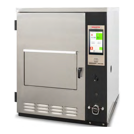
Broaster VF-2 Service & Parts Manual
Ventless fryer
Hide thumbs
Also See for VF-2:
- Service & parts manual (96 pages) ,
- Installation & operation manual (60 pages) ,
- Quick start manual (3 pages)
Table of Contents
Advertisement
Quick Links
SERVICE & PARTS MANUAL
®
BROASTER
VF-2 & VF3i
VENTLESS FRYER
Be sure ALL installers read, understand, and have access to this manual at all times.
Genuine Broaster Chicken®, Broasted®, Broaster Chicken®, Broaster Foods®. and Broasterie® are registered
trademarks. Usage is available only to licensed operators with written authorization from the Broaster Company.
Broaster Company
2855 Cranston Road, Beloit, WI 53511-3991
608/365-0193 broaster.com
© 2006 Broaster Company
16501 7/06 Rev 10/22
Printed In U.S.A.
Advertisement
Table of Contents
Troubleshooting

Subscribe to Our Youtube Channel
Related Manuals for Broaster VF-2


Summary of Contents for Broaster VF-2
- Page 1 Be sure ALL installers read, understand, and have access to this manual at all times. Genuine Broaster Chicken®, Broasted®, Broaster Chicken®, Broaster Foods®. and Broasterie® are registered trademarks. Usage is available only to licensed operators with written authorization from the Broaster Company. Broaster Company 2855 Cranston Road, Beloit, WI 53511-3991 608/365-0193 broaster.com...
- Page 3 Indicates a potentially hazardous situation which, if not avoided, could result in minor injury, property damage or both. All adjustments and repairs shall be made Rags or paper containing by an authorized Broaster Company repre- cooking oil can catch fire sentative. if exposed to heat. Laundering will not remove the oil.
-
Page 5: Table Of Contents
BREAK ROD REPLACEMENT ................... 3 - 7 4 - COOKING AREA ......................4 - 1 ELEMENT SHAFT REMOVAL ..................4 - 1 TEMPERATURE SENSOR PROBE................4 - 3 HI LIMIT CONTROL ....................4 - 4 HEATING ELEMENT....................4 - 6 broaster.com Manual #16501 7/06 Rev 10/20... -
Page 6: Vf2
FIRE SUPPRESSION SYSTEM VF2 ............... 7 - 17 VF3i............... 7 - 18 BASKET LIFT MECHANISM..................7 - 19 COOKING WELL GROUP ..................7 - 20 8 - PART NUMBER LIST ....................8 - 1 broaster.com Manual #16501 7/06 Rev 10/20... - Page 7 If no component operates, check main Be sure all connections are tight. If power supply. Be sure main circuit breaker power supply is proper, see TROU- is ON and main fuses are good. BLESHOOTING section. broaster.com Manual #16501 8/06 Rev 2/15...
- Page 8 WIRING DIAGRAM VF2: SUPPRESSOR PURPLE PURPLE YELLOW WHITE WHITE BLUE SLEEVE BLUE WHITE C1 240V COIL C2 120V COIL HEATER 208 OR 240V 120V broaster.com Manual #16501 8/06 Rev 2/15...
- Page 9 WIRING DIAGRAM VF2: effective S/N VF2F70041x broaster.com Manual #16501 8/06 Rev 2/15...
- Page 10 WIRING DIAGRAM VF2: effective S/N VF2F90XXXX broaster.com Manual #16501 8/06 Rev 2/15...
- Page 11 WIRING DIAGRAM VF2: effective S/N VF2L90XXXX broaster.com Manual #16501 8/06 Rev 2/15...
- Page 12 WIRING DIAGRAM VF3i: broaster.com Manual #16501 8/06 Rev 2/15...
- Page 13 WIRING DIAGRAM VF3i: effective S/N VF3G900320 broaster.com Manual #16501 8/06 Rev 2/15 broaster.com Manual #16501 8/06 Rev 2/15...
- Page 14 WIRING DIAGRAM VF3i: effective S/N VF3H90XXXX broaster.com Manual #16501 8/06 Rev 10/20...
- Page 15 WIRING DIAGRAM - VF-3 / VF-2 effective S/N VF3J02112 and VF2_02003G broaster.com Manual #16501 8/06 Rev 10/20...
-
Page 16: Vf2 Export
WIRING DIAGRAM VF2 EXPORT: 1-10 broaster.com Manual #16501 8/06 Rev 2/15... - Page 17 WIRING DIAGRAM VF2 EXPORT: effective S/N VF2F90XXXX 1-11 broaster.com Manual #16501 8/06 Rev 2/15...
- Page 18 WIRING DIAGRAM VF2 EXPORT: effective S/N VF2L90XXXX 1-12 broaster.com Manual #16501 8/06 Rev 2/15...
-
Page 19: Vf3I Export
WIRING DIAGRAM VF3i EXPORT: broaster.com Manual #16501 8/06 Rev 2/15 1-13... - Page 20 WIRING DIAGRAM VF3i EXPORT: effective S/N VF3F90XXXX 1-14 broaster.com Manual #16501 8/06 Rev 2/15...
- Page 21 WIRING DIAGRAM VF3i EXPORT: effective S/N VF3H90XXXX 1-15 broaster.com Manual #16501 8/06 Rev 2/15...
- Page 22 WIRING DIAGRAM - VF-3 / VF2 Export effective S/N>VF3J02112, VF2_02003G 1-16 broaster.com Manual #16501 8/06 Rev 2/15...
-
Page 23: Front Panel
OFF: Turns power to unit off. Heat On Indicator Light: Illuminates when oil is being heated. Light goes off when oil reaches set temperature. broaster.com Manual #16501 8/06 Rev 10/20... -
Page 24: Operational Lockouts
360F) rized Broaster Company representa- tive. Action: If desired, press keypad num- bers to change displayed value then press Cook Temperature Button once to enter new value into memory. broaster.com Manual #16501 8/06 Rev 10/20... -
Page 25: Preset Cook Mode
TIME and TEMP displays flashing. Action: Press a button, 0 thru 9, corre- sponding to the desired preset. Response: The TIME display will show “P__X”, where X is the preset selected. broaster.com Manual #16501 8/06 Rev 10/20... -
Page 26: Warning Displays
Even if all presets are not All controller functions and heat source are programed the reset but- disabled during this condition. ton must be pressed until “-9” appears then press reset button once more to hold programs. broaster.com Manual #16501 8/06 Rev 10/20... -
Page 27: Display Actual Temperature
Check cooking oil temperature one inch below oil surface in the center of cooking well. Using keypad, enter temperature to match controller display with calibrat- ing thermometer. Press temp button to exit calibration. broaster.com Manual #16501 8/06 Rev 10/20... -
Page 28: Front Panel Assembly
If 5 volts are not present check the power DISPLAY BOARD (upper) input to the Control Board (bottom board). The display board (3) displays time and temperature. Remove F/C jumper (18) to display temperature in Celsius. broaster.com Manual #16501 8/06 Rev 10/20... -
Page 29: Control Board (Lower)
Disconnect speaker plug (13) from control board (6). Disconnect heater wires #19 & 20 from terminals (14) using needle nose pliers. Disconnect fan wires #41 & 42 from terminals (15) using needle nose pliers. broaster.com Manual #16501 8/06 Rev 10/20... -
Page 30: Control Board Power Input
Make sure the receptacle on the speaker wire is attached to the control board as shown above to eliminate any problems with operation of the unit. broaster.com Manual #16501 8/06 Rev 10/20... -
Page 31: Speaker
Loosen, but do not remove, the three transformer is faulty. hex nuts holding speaker (8) to the back of the control panel until speaker (8) can be slipped out from under washers (9). Install new speaker in reverse order. broaster.com Manual #16501 8/06 Rev 10/20... - Page 32 Replacement: See ACCESS FOR SERVICE. Disconnect yellow transformer wires from Control Board (6). Disconnect the black transformer wires. Remove two hex nuts, then remove transformer (7). Install new transformer. Reassemble in reverse order. 2-10 broaster.com Manual #16501 8/06 Rev 10/20...
-
Page 33: Smarttouch Display
Cook Cycles POWER BROASTER COMPANY ● BELOIT, WI USA PARTS AND SERVICE SUPPLIED BY AUTHORIZED BROASTER DISTRIBUTORS The cooking idle screen displays the current set- tings for time and temperature along with the recipe item that is selected. The temperature dis-... - Page 34 POWER POWER BROASTER COMPANY ● BELOIT, WI USA BROASTER COMPANY ● BELOIT, WI USA PARTS AND SERVICE SUPPLIED BY AUTHORIZED BROASTER DISTRIBUTORS PARTS AND SERVICE SUPPLIED BY AUTHORIZED BROASTER DISTRIBUTORS COOKING PRESET SELECTION As cooking begins, the remaining cooking time Select the desired preset menu item by pressing will be displayed.
- Page 35 POWER POWER BROASTER COMPANY ● BELOIT, WI USA BROASTER COMPANY ● BELOIT, WI USA PARTS AND SERVICE SUPPLIED BY AUTHORIZED BROASTER DISTRIBUTORS PARTS AND SERVICE SUPPLIED BY AUTHORIZED BROASTER DISTRIBUTORS PRODUCT DOOR MANUAL TIME/TEMP SETTING If the product door is opened, a notice will be If the Manual Time/Temp is enabled in Setup, a displayed on the screen as appears above.
- Page 36 POWER POWER BROASTER COMPANY ● BELOIT, WI USA BROASTER COMPANY ● BELOIT, WI USA PARTS AND SERVICE SUPPLIED BY AUTHORIZED BROASTER DISTRIBUTORS PARTS AND SERVICE SUPPLIED BY AUTHORIZED BROASTER DISTRIBUTORS RESETTING THE COOK CYCLE FIRE SYSTEM INSECTION REMINDER The display will provide a reminder when the...
- Page 37 POWER POWER BROASTER COMPANY ● BELOIT, WI USA BROASTER COMPANY ● BELOIT, WI USA PARTS AND SERVICE SUPPLIED BY AUTHORIZED BROASTER DISTRIBUTORS PARTS AND SERVICE SUPPLIED BY AUTHORIZED BROASTER DISTRIBUTORS STATUS MESSAGES SERVICE MESSAGES Status messages will be displayed whenever the...
- Page 38 POWER POWER BROASTER COMPANY ● BELOIT, WI USA BROASTER COMPANY ● BELOIT, WI USA PARTS AND SERVICE SUPPLIED BY AUTHORIZED BROASTER DISTRIBUTORS PARTS AND SERVICE SUPPLIED BY AUTHORIZED BROASTER DISTRIBUTORS SETUP TEMPERATURE SETTINGS The Setup tab provides a means to change the...
- Page 39 POWER POWER BROASTER COMPANY ● BELOIT, WI USA BROASTER COMPANY ● BELOIT, WI USA PARTS AND SERVICE SUPPLIED BY AUTHORIZED BROASTER DISTRIBUTORS PARTS AND SERVICE SUPPLIED BY AUTHORIZED BROASTER DISTRIBUTORS PIN MAINTENANCE ALERT SETTINGS A four digit PIN may be employed to limit the...
- Page 40 POWER POWER BROASTER COMPANY ● BELOIT, WI USA BROASTER COMPANY ● BELOIT, WI USA PARTS AND SERVICE SUPPLIED BY AUTHORIZED BROASTER DISTRIBUTORS PARTS AND SERVICE SUPPLIED BY AUTHORIZED BROASTER DISTRIBUTORS EDITING PRESET MENU ITEMS EDITING PRESET MENU ITEMS The control comes standard with many Broaster This screen allows the operator to edit an exist- food item recipes and menu item images.
- Page 41 Serial Number: 123456789 Install Date: 09/29/2020 Firmware Version 0.09 POWER BROASTER COMPANY ● BELOIT, WI USA PARTS AND SERVICE SUPPLIED BY AUTHORIZED BROASTER DISTRIBUTORS ERROR CODE DIAGNOSTICS SERVICING THE SMARTTOUCH DISPLAY This screen provides a history of any error messages that were generated. The control...
-
Page 42: Fire Suppression System
Section 3, Fire AUTOMATIC OPERATION Suppression Maintenance and Replace- ment of the VF-2/VF-3i Service & Parts Upon the detection of a fire, the system will Manual. automatically operate. The fusible link in the... -
Page 43: Monthly Inspection
1. A check to see that the hazard has not Fire Suppression system, the affected changed. parts must be replaced or repaired. broaster.com Manual #16501 8/06 Rev 01-22... -
Page 44: Twelve Year
Broaster Dis- tributor for sources. 3. If the cylinder shows no signs of rup- ture or distortion, recharge the Fire Suppression system in accordance with NFPA 17A guidelines. -
Page 45: Semi-Annual Inspection & Maintenance Log
Date __________ I & M by __________ Date __________ I & M by __________ Date __________ I & M by __________ Date __________ I & M by __________ Date __________ I & M by __________ broaster.com Manual #16501 8/06 Rev 02-15... - Page 46 (A) and placing it above ele- ment retainer (B). 6. Remove cooking well (5). 3. Open Access door by lifting door latch and turning CCW. 4. Remove food basket (3), platform (4). broaster.com Manual #16501 8/06 Rev 02-15...
-
Page 47: Fire Extinguisher Replacement
11. Reconnect piping (17) to the fire extin- guisher. 12. Reinstall the mounting strap (15) using nuts (16). 13. Insert the ball end of the new “Fuse- Link” cable (10) into cable receiver (11) then insert hitch pin (9). broaster.com Manual #16501 8/06 Rev 02-15... -
Page 48: Fusible Link Replacement
5. Insert allen screw (20) and tighten until the rod is not sliding left or right. Be careful not to overtighten or the rod will break. 6. Remove safety pin (6) from fire extin- guisher. 7. Replace Access Panel. broaster.com Manual #16501 8/06 Rev 02-15... -
Page 50: Cooking Area
3. Remove food basket (3) and platform (4). 4. Raise the element by raising the ele- ment are (5) and placing it above the elemenn retainer (6). 5. Remove Cooking Pot (7). broaster.com Manual #16501 7/06 Rev 2/15... - Page 51 9. Disconnect the Heating Element wires panel. from the C2 contactor (12). 15 Reassemble in reverse order. Heating Element Wire Heating Element Wire broaster.com Manual #16501 7/06 Rev 2/15...
-
Page 52: Temperature Sensor Probe
Element Shaft to damage any of the remaining components. 6. Install new probe in the same location as old probe. End of probe sheath should be 1/8” above nut (23) when installed properly. broaster.com Manual #16501 7/06 Rev 2/15... -
Page 53: Hi Limit Control
If alarm light is lit, the control has tripped. CONDITION 2: Probe Failure 1. Disconnect power from the unit. 2. Disconnect probe wires from terminals 6 & 7 and connect a new probe. Yellow to + and Red to -. broaster.com Manual #16501 7/06 Rev 2/15... - Page 54 5. Carefully pull probe (29) out of Con- nector Box. DO NOT allow wires being pulled out of Element Shaft to damage any of the remaining components. Hi-Limit Probe 4. Install new control in reverse order. broaster.com Manual #16501 7/06 Rev 2/15...
- Page 55 3. Remove screws (32) and remove Heat- from the device by unplugging the appliance ing Element from Connector box (18). for it to reset.The part number is 18025 CONTROL- HI LIMIT, 415F,120VAC. 4. Reassemble in reverse order. broaster.com Manual #16501 7/06 Rev 2/15...
-
Page 56: Electrical Components
1. See Access For Service. 2. Remove Access Panel Retaining 2. Open Access Door (3) by lifting Access Screw (1). Raise the Access Panel (2) Door Latch (4) and turning CCW. and pull outward. broaster.com Manual #16501 7/06 rev 2/15... - Page 57 High Limit Relay (7) and the UP & DOWN Switch (8). 7. Remove Motor (13) by removing four hex bolts (14). 5. Disconnect Basket Lift connector arm 8. Assemble in reverse order. (9) by removing hex nut and washer (10). broaster.com Manual #16501 7/06 rev 2/15...
-
Page 58: Switches
(17) with an ohmmeter. Meter should indicate an open circuit. If not switch is faulty. 5. Reassemble in reverse order. 6. Check to be sure cam properly actu- PUSH TO ACTIVATE ates the switch after assembly. broaster.com Manual #16501 7/06 rev 2/15... -
Page 59: Basket Down Swtich
(12) is pointing toward the floor (be sure magnet is near switch (19), check across wire leads (20). Meter should indicate a closed circuit. If not, switch is faulty. Basket Down Switch Replacement: 1. See Motor Replacement, step 1-3. broaster.com Manual #16501 7/06 rev 2/15... -
Page 60: Product Door Swtich
If not, switch is faulty. Product Door Switch Replacement 1. See Access for Service. 2. Loosen the hex nut and slide switch out of bracket. 3. Disconnect switch lead wires (24) if not already disconnected. broaster.com Manual #16501 7/06 rev 2/15... - Page 61 If not, switch is faulty. 3. With Access Door closed and latched check across wire leads (22). Meter should indicate a closed circuit. If not, switch is faulty. Spring Retaining Clip (2) broaster.com Manual #16501 7/06 rev 2/15...
- Page 62 1. See Access For Service. 2. Disconnect switch leads (26). 3. With the Element in the down position, check across the wire leads (26). Meter should indicate an open circuit. If not, switch is faulty. broaster.com Manual #16501 7/06 rev 4/22...
- Page 63 3. Remove Filter Cartridge (32) from unit. 4. Remove nuts holding pressure switch in place. 5. Carefully remove tubing (35) con- nected to switch. 6. Reassemble in reverse order. broaster.com Manual #16501 7/06 rev 2/15...
- Page 64 1. Loosen the hex nuts and slide switch out of bracket. 2. Disconnect lead wires (38) if not already disconnected. 3. Reassemble in reverse order making sure end of switch is against the front panel and slid fully into bracket. broaster.com Manual #16501 7/06 rev 01/22...
-
Page 65: Grease Filter Switch
(45). Meter should tray inside boot (44). indicate an open circuit. If not, switch is faulty. The leads for this switch are in the electrical control compartment. 5-10 broaster.com Manual #16501 7/06 rev 2/15... - Page 66 MORE THEN 1/4 TURN PAST FIN- removed from. See below. GER TIGHT. 8. Push boot (44) over fitting (47) until the end is touching the side wall as shown below. Unit is now ready to operate. 5-11 broaster.com Manual #16501 7/06 rev 2/15...
-
Page 67: Pressure Switch Replacement
4. Install new switch in reverse order. 4. Meter should indicate a closed circuit. If not, switch is faulty. 5. Apply a gentle vacuum to the vacuum port. Meter should indicate an open circuit. If not, switch is faulty. 5-12 broaster.com Manual #16501 7/06 rev 2/15... -
Page 68: Troubleshooting
6 - TROUBLESHOOTING All adjustments and repairs shall be made by an authorized Broaster Company representative. ELECTRICAL TIPS COMPLAINT CAUSE REMEDY 1. Unit OFF 1. Press ON button 2. Main power OFF 2. Turn ON POWER light not illumi- 3. Unplugged 3. -
Page 69: Indicator Lights
The series of indicator lights on the Display Panel check for specific conditions that make the VF-2 Fryer safe to operate. The unit will not start or continue a cook cycle if any of the follow- ing indicator lights are lit. -
Page 70: Solid State Controller Tips
2. Old product 2. Discard 1. Product stuck together 1. Distribute product evenly White spots 2. Food basket overloaded in basket while loading 2. Decrease load size Dark spots 1. Dirty oil 1. Filter or replace broaster.com Manual #16501 7/06 Rev 2/15... -
Page 71: Troubleshooting Flow Chart
Temperature didn't rise 6 degrees in 3 minutes. Check controller, C2, wiring and connections. PROB: Problem with temperature sensing. Check controller, probe, speaker. FAIL: Internal fault detected or temperature fluctuation. Check controller or probe. broaster.com Manual #16501 7/06 Rev 2/15... - Page 72 Adjust or Replace Lower element Pressure Differential Element switch Troubleshoot 12VDC on purple Element Up wires from I/O Interlock Board? Replace 120VAC present Replace between wires 25 Blower Board and 37? Replace Fan Relay broaster.com Manual #16501 7/06 Rev 2/15...
- Page 73 Is 120VAC present between wires 21 Replace & neutral for 1 motor second? Trace lost Replace connection controller Is 12VDC present Replace between wires 1 & Relay 2 for one second? Replace I/O board broaster.com Manual #16501 7/06 Rev 11/17...
- Page 74 Does Air Filter Replace need to be Air Filter replaced? Does oil need to be Change filtered or or flter changed? Check all sealant locations and look for air bypassing the filter broaster.com Manual #16501 7/06 Rev 2/15...
-
Page 76: Parts
7 - PARTS All adjustments and repairs shall be made by an authorized Broaster Company representative. PANELS AND DOORS T DO T UP R FL R FI FI LT LI MI T RE FI RE W ER O FF F I R... -
Page 77: Filter Tray Vf2
FILTER TRAY - VF2 broaster.com Manual #16501 7/06 Rev 2/15... -
Page 78: Vf3I
FILTER TRAY - VF3i broaster.com Manual #16501 7/06 Rev 2/15... -
Page 79: Controller And Components
CONTROLLER AND COMPONENTS broaster.com Manual #16501 7/06 Rev 2/15... - Page 80 CONTROLLER AND COMPONENTS broaster.com Manual #16501 7/06 Rev 2/15...
- Page 81 INTERLOCK SWITCHES - VF2 broaster.com Manual #16501 7/06 Rev 01/22...
- Page 82 INTERLOCK SWITCHES - VF2 * Replaced by switch #18021 effective VF2CC91003G. Previous units replace #16449 switch with #18021 switch and #18022 mounting plate. broaster.com Manual #16501 7/06 Rev 10/20...
- Page 83 INTERLOCK SWITCHES - VF2 (effective S/N VF2L900172) * Replaced by switch #18021 effective VF2CC91003G. Previous units replace #16449 switch with #18021 switch and #18022 mounting plate. broaster.com Manual #16501 7/06 Rev 10/20...
-
Page 84: Vf3I
INTERLOCK SWTICHES - VF3i broaster.com Manual #16501 7/06 Rev 08/22... - Page 85 INTERLOCK SWTICHES - VF3i (effective S/N VF3H900410) 7-10 broaster.com Manual #16501 7/06 Rev 08/22...
-
Page 86: Contactor And Relay Mounting Vf2
CONTACTOR AND RELAY MOUNTING - VF2 7-11 broaster.com Manual #16501 7/06 Rev 01/22... - Page 87 CONTACTOR AND RELAY MOUNTING - VF2: (effective S/N VF2L900172) 7-12 broaster.com Manual #16501 7/06 Rev 01/22...
-
Page 88: Vf3I
CONTACTOR AND RELAY MOUNTING - VF3i 7-13 broaster.com Manual #16501 7/06 Rev 01/22... - Page 89 CONTACTOR AND RELAY MOUNTING - VF3i: effective S/N VF3G900320 7-14 broaster.com Manual #16501 7/06 Rev 01/22...
-
Page 90: Heating Element And Lift Mechanism Vf2
HEATING ELEMENT AND LIFT MECHANISM VF2 7-15 broaster.com Manual #16501 7/06 Rev 04/22... -
Page 91: Vf3I
HEATING ELEMENT AND LIFT MECHANISM VF3i 7-16 broaster.com Manual #16501 7/06 Rev 2/15... -
Page 92: Fire Suppression System Vf2
FIRE SUPPRESSION SYSTEM VF2 7-17 broaster.com Manual #16501 7/06 Rev 2/15... -
Page 93: Vf3I
FIRE SUPPRESSION SYSTEM VF3i 7-18 broaster.com Manual #16501 7/06 Rev 2/15... -
Page 94: Basket Lift Mechanism
BASKET LIFT MECHANISM 7-19 broaster.com Manual #16501 7/06 Rev 2/15... -
Page 95: Cooking Well Group
COOKING WELL GROUP 7-20 broaster.com Manual #16501 7/06 Rev 2/15... - Page 97 SWITCH- MINITURE LO VLT/LO AMP 15274 LOCKNUT- TOPLOCK, 1/4-20 15275 WASHER- FLAT, 1/4", EXH VALVE 15898 ELEMENT- 208V VF3 15906 TRAY WELD- SPLASH, VF3 15917 PIVOT- ELEMENT SWING 15918 BUSHING- ELEMENT SWING 15926 BRACKET- ARM PIVOT PIN broaster.com Manual#16501 7/06 Rev 2/15...
- Page 98 16259 SCREW SOC HD CAP #10-32X .375 16263 INDICATOR - COLD OIL LEVEL 16277 ARC SUPPRESSOR ASSY 16297 BLOWER GASKET 16327 HEATING ELEMENT- 240V 5500W 16330 HEATING ELEMENT- 208V 5500W 16331 OVERLAY- PULL STATION, VF2 broaster.com Manual#16501 7/06 Rev 2/15...
- Page 99 16259 SCREW SOC HD CAP #10-32X .375 16263 INDICATOR - COLD OIL LEVEL 16277 ARC SUPPRESSOR ASSY 16297 BLOWER GASKET 16327 HEATING ELEMENT- 240V 5500W 16330 HEATING ELEMENT- 208V 5500W 16331 OVERLAY- PULL STATION, VF2 broaster.com Manual#16501 7/06 Rev 2/15...
- Page 100 SHELF WELD- FAN, VF2 16460 BRACKET- MTG, PROS SW 16461 FAN- MAIN VENTILATION 16463 CONTROL- HI LIMIT, 450F 16468 ARM WELD- UPPER LIFT, VF2 16470 ARM ASSY- BASKT LFT, LOWR 16471 BUSHING- FILT SUPP, SMALL, VF2 broaster.com Manual#16501 7/06 Rev 2/15...
- Page 101 SPRING- PRODUCT DOOR, VF3i 16574 DOOR WELD- ACCESS, VF3i 16575 TUBE- FIRE AGNT, TNK/TEE, VF3i 16576 TUBE- FIRE AGNT, TEE/TOP, VF3i 16577 TUBE- FIRE AGNT, TEE/BTM, VF3i 16578 FITTING- LWR NOZL, 60 DG, VF3i 16582 LIFT WELD, VF3i broaster.com Manual#16501 7/06 Rev 2/15...
- Page 102 18098 PROBE - FORMED, VF2 HI-LIMIT 18107 CONTROL, TOUCHSCREEN, VF 18108 ASM, CHASSIS, W/ OVERLAY, VF2 18109 ASM, CHASSIS, W/ OVERLAY, VF3 18110 PLATE- SPEC. UNIVERSAL, VF 70205 SCREW PH HD #8-32 X .375 SS broaster.com Manual#16501 7/06 Rev 2/15...
- Page 103 SERVICE NOTES Manual #16501 8/06...
- Page 104 SERVICE NOTES Manual #16501 8/06...
- Page 105 SERVICE NOTES Manual #16501 8/06...
- Page 108 Broaster Company 2855 Cranston Road, Beloit, WI 53511-3991 608/365-0193 broaster.com...
Need help?
Do you have a question about the VF-2 and is the answer not in the manual?
Questions and answers