
Related Manuals for Zeiss CONTURA


Summary of Contents for Zeiss CONTURA
- Page 1 CONTURA Coordinate measuring machine Operating instructions (Translation of the original operating instructions)
- Page 2 Violations shall result in claims for damages. © ZEISS. All rights reserved. This manual is subject to change, and the ZEISS product described as well as the components therein are subject to technical modifications. All product names are registered trademarks or trademarks of the re- spective owners.
-
Page 3: Table Of Contents
CMM ........................ 2-2 Probing system ...................... 2-3 Changer rack ...................... 2-4 Rotary table ...................... 2-4 Safe operation of the CMM ............ 2-6 Operator requirements................... 2-6 Defining a competent specialist................ 2-6 Requirements for safe use .................. 2-7 Requirements for automatic measuring runs............ 2-8 Basic safety instructions.................. 2-9 61211-1310402 CONTURA Table of contents... - Page 4 Service unit for compressed air supply .............. 3-6 MSR changer rack .................... 3-7 ProMax E changer rack (option) ................ 3-9 Control unit and operation ............ 3-11 Controller ...................... 3-11 Operation ...................... 3-11 Probing system................ 3-15 Types of probing systems .................. 3-15 Contact probing systems.................. 3-15 Optical Probing Systems .................. 3-17 61211-1310402 CONTURA Table of contents...
- Page 5 Connecting the power supply ................ 6-2 Connecting the compressed air supply .............. 6-2 Setting up the changer rack ................... 6-3 Visual check and check list ................... 6-10 Switching the CMM on.............. 6-12 Safety measures and notes................... 6-12 CMM starting sequence .................. 6-12 61211-1310402 CONTURA Table of contents...
- Page 6 Preparation for measuring operation .......... 7-9 Prerequisites for a precise measuring run.............. 7-9 Reference point travel .................... 7-9 Stylus system qualification.................. 7-11 Temperature compensation ................. 7-17 Probing the workpiece .............. 7-20 How to ensure correct measurement .............. 7-20 What you should know! .................. 7-20 61211-1310402 CONTURA Table of contents...
- Page 7 In case of air conditioning failure................ 8-6 Service features................ 8-7 Support........................ 8-7 Teleservice ...................... 8-7 Chapter 9 Maintenance and care Maintenance ................. 9-2 Care.................... 9-4 What you should know! .................. 9-4 Safety instructions.................... 9-5 Measures of precaution .................. 9-5 Overview ....................... 9-6 Care and cleaning .................... 9-7 Inspection measures..................... 9-12 61211-1310402 CONTURA Table of contents...
- Page 8 Chapter 10 Shutdown and disposal Decommissioning ................ 10-2 Disposal.................. 10-3 Package ....................... 10-3 CMM ........................ 10-3 Glossary Alphabetic index 61211-1310402 CONTURA Table of contents...
-
Page 9: Preface
Preface About this document The CONTURA coordinate measuring machine (CMM) is described in these operating instructions. These operating instructions are intended for operators and users of the coordinate measuring machine. 61211-1310402 CONTURA Preface... -
Page 10: Configuration Of Safety Instructions
CAUTION A »caution« indicates a personal health hazard. Non-observance of this safety instruction when the described risk oc- curs may cause slight to moderate injuries. Example: Risk of minor crushing of the limbs caused by small loads. 61211-1310402 CONTURA Preface... - Page 11 This symbol refers to possible damage to the CMM. Non-observance of this safety instruction when the event occurs may cause damage to the CMM or one of its components. Example: Collision of the ram with a workpiece. 61211-1310402 CONTURA Preface...
-
Page 12: Markup Elements
ZEISS Company name CAUTION! The measur- Safety instructions embedded in the text. ing table must be clean. Note: Pay attention to the Note embedded in the text. correct orientation of the qualification marks. Representation of position numbers in texts 61211-1310402 CONTURA Preface... -
Page 13: Chapter 1 Introduction
Introduction Introduction This chapter contains: General specifications .................. 1-2 Warranty ..................... 1-6 61211-1310402 CONTURA... -
Page 14: General Specifications
General specifications General specifications Delivery package The standard version of the CONTURA coordinate measuring machine comprises the following components: – Coordinate measuring machine (CMM) – Controller – Control console (standard version) – Computer with peripheral devices – Software, for example CALYPSO –... -
Page 15: Ce Marking
If modifications are made to the machinery without our prior approval, this declaration will no longer be valid. Designation of the ma- Coordinate measuring machine chine: CMM type: CONTURA Additional EU directives: – EMC Directive (2014/30/EU) – RoHS Directive (2011/65/EU) Applied harmonized stan- – EN 60204-1 dards, in particular: –... -
Page 16: Separate Document
The following documents are delivered with each CMM: – BP26SE control console – Sensors (information on probing systems) – AirSaver Option The following documents are delivered if the CMM is equipped with the corresponding option. – Rotary table – LineScan 61211-1310402 CONTURA... - Page 17 General specifications Documentation on data storage device The above documents and others can also be found on the supplied data carrier. 61211-1310402 CONTURA...
-
Page 18: Warranty
– in case of alteration of the coordinate measuring machine version delivered by us, – if maintenance work is not carried out by personnel specially trained at ZEISS, – if measures for care are not taken by the operator or user according to the specified measures, –... - Page 19 Safety Safety This chapter contains: Intended use.................... 2-2 Safe operation of the CMM ................ 2-6 Safety on the CMM.................. 2-14 Checking the safety devices ............... 2-16 61211-1310402 CONTURA...
-
Page 20: Intended Use
– Holding and securing a rotary table (optional) – Securing the workpieces and fastening the qualification tool, changer rack and rotary table by use of the threaded bushings provided in the measuring table. – Moving workpieces by means of the rotary table. 61211-1310402 CONTURA... -
Page 21: Probing System
Functions of the contact probe: – Holding the stylus system. – Exact positioning of the stylus system. – Detecting the stylus system deflection and transmitting the signal to the computer. The computer calculates the coordinates of the probed point. 61211-1310402 CONTURA... -
Page 22: Changer Rack
Rotary tables also cal objects facilitate the measurement of prismatic parts. Functions of the rotary table: – Holding the workpiece – Positioning the workpiece – Probing with rotary table – Scanning with rotary table 61211-1310402 CONTURA... - Page 23 Rotary tables must not be used for purposes contrary to the intended use. Examples of reasonably foreseeable misuse: – The rotary table must not be used as storage surface. – The rotary table is not to be sat upon. 61211-1310402 CONTURA...
-
Page 24: Safe Operation Of The Cmm
Work to be carried out by a competent specialist – CMM installation. – Maintenance work on the CMM. – Work on the electrical equipment, for example controller. – Preparation of the measurement: Workpiece setting, creation of measurement plans and automatic measuring runs. 61211-1310402 CONTURA... -
Page 25: Requirements For Safe Use
18 Always keep the control console within reach in order to be able to press the EMERGENCY STOP button in cases of emergency. 19 Perform a homing run. 20 Read the notes regarding the end of the measuring operation. 61211-1310402 CONTURA... -
Page 26: Requirements For Automatic Measuring Runs
– It must be ensured that all persons are located outside of the demar- cated area. – If the constant presence of the operator during batch measurement cannot be guaranteed, the relevant safety regulations for unat- tended operation must be observed. 61211-1310402 CONTURA... -
Page 27: Basic Safety Instructions
— Keep a safe distance to moving parts during manual operation. — Ensure that nobody is at risk during manual operation of the ma- chine. — Keep a safe distance away from the CMM during automatic mea- surement runs. 61211-1310402 CONTURA... - Page 28 Risk of injury due to tripping over exposed cables or acces- sories. Falling and concussion injuries on head and body. ü Cables and accessories must not become a tripping or stumbling hazard. — Run the cables through cable ducts. — Install accessories securely at the predefined locations. 2-10 61211-1310402 CONTURA...
-
Page 29: General Precautions
Delimiting the working area The working area around the CMM should be delimited with regard to conduct routes. The working area may be delimited as follows: – Floor marking – Barrier tape, especially in the case of automatic measurement runs. 2-11 61211-1310402 CONTURA... - Page 30 – Do not carry out any modifications on the CMM. Maintenance work Any work and maintenance work on the CMM may only be carried out by ZEISS service engineers or trained personnel authorized by ZEISS. Sufficient illumination Sufficient illumination is required for safe operation of the CMM.
-
Page 31: Safety Instructions
Adhesive labels on the LineScan with a blue laser (2-8) While the measuring software is running, the probe must not be changed by using the key combination of the control console. — Use the functions of the measuring software to replace the probe. 2-13 61211-1310402 CONTURA... -
Page 32: Safety On The Cmm
– Unlock the button by turning it. Then the button automatically releases and unlocks. NOTE The EMERGENCY STOP button should only be pressed in cases of emer- gency. A separate key is used for switching off the drives. 2-14 61211-1310402 CONTURA... - Page 33 Safety on the CMM If you want to switch the drives off during daily operation, then you should use the key shown here. The LED above the key indicates whether the drives are on or off. 2-15 61211-1310402 CONTURA...
-
Page 34: Checking The Safety Devices
— Try to stop the movement (v ) manually by pushing against the marked spot on the housing cover of the ram (F). This increases the thrust of the drives. If the shearing force exceeds a certain value, all drives switch off. 2-16 61211-1310402 CONTURA... - Page 35 Under normal circumstances, the force of your hand should suffice to stop movement. If the movement cannot be stopped in this way, the protective circuit must be checked immediately by a ZEISS service engi- neer. NOTE If you can stop the travel movements, you will need to reactivate the drives.
- Page 36 Under normal circumstances, the force of your hand should suffice to stop movement. If the movement cannot be stopped in this way, the protective circuit must be checked immediately by a ZEISS service engi- neer. NOTE If you can stop the travel movements, you will need to reactivate the drives.
- Page 37 Description Description This chapter contains: Designation of a CMM................. 3-2 Design of the CMM .................. 3-3 Components and function ................ 3-4 Control unit and operation................. 3-11 Probing system .................. 3-15 61211-1310402 CONTURA...
-
Page 38: Designation Of A Cmm
The designation of your CMM is specified on the type plate. The type plate is attached to the measuring table. XXXXXXXX Year: XXXX S/N: XXXXXX XXXXXX-XXXX-XXX Coordinate Measuring Machine Made in Germany 1 Series and identification of the CMM 2 Serial number 3 CMM number 4 Year of manufacture 61211-1310402 CONTURA... -
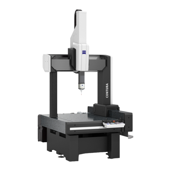
Page 39: Design Of The Cmm
Design of the CMM Design of the CMM A CMM of the CONTURA series is shown below. CONTURA (HTG version) Ram cover X bridge crossbeam Drive-side column Probe with stylus system Guideway on the drive side Controller box Guideway Measuring table... -
Page 40: Components And Function
Components and function Components and function Bridge-type CMM The CONTURA is a bridge-type coordinate measuring machine. The bridge is composed of an X bridge crossbeam and two columns. The X carriage in which the ram is guided moves along the crossbeam. The bridge travels in the Y axis. -
Page 41: Coordinate Axes
B Top view X axis (crossbeam) The crossbeam is mounted on columns and supports the X carriage. The X carriage is guided along the X-bridge crossbeam and can be moved back and forth. to enable probing in the X axis. 61211-1310402 CONTURA... -
Page 42: Reference Standard
It is possible to mount more than one reference sphere onto the reference sphere holder. Note: Addi- tional reference spheres have to be installed by a ZEISS service engineer. Reference sphere holder RSH 214 1 Reference sphere... -
Page 43: Msr Changer Rack
A possible third profile rail is optional. The profile rails are mounted on the frame sup- port. The changer rack is preassembled. The height of the changer rack de- pends on the CMM. 61211-1310402 CONTURA... - Page 44 Foot profile The foot profile consists of a mounting profile and a guide profile. These two profiles form a unit. The mounting profile has a through hole for fastening to the measuring table. The guide element features a groove 61211-1310402 CONTURA...
-
Page 45: Promax E Changer Rack (Option)
Separate operating instructions are available for ProMax E. These oper- ating instructions contain detailed information on the changer rack. Installation NOTE Three threaded bushings are provided on the rear of the measuring ta- ble. These threaded bushings are used to attach the changer rack. See also 61211-1310402 CONTURA... - Page 46 Components and function Attaching the holders to the profile rail [ ⇨ 6-9] ➤ — 3-10 61211-1310402 CONTURA...
-
Page 47: Control Unit And Operation
Control unit and operation Control unit and operation Controller The controller for CONTURA is housed in a controller box on the rear side of the CMM. The CONTURA is equipped with a 32 bit controller. This controller has the designation C99m. - Page 48 Direction Action Movement of the joystick, ram and probe X axis – Push the joystick to the left. The ram moves to the left. – Push the joystick to the right. The ram moves to the right. 3-12 61211-1310402 CONTURA...
- Page 49 2. Push the joystick to the left. The rotary table turns clock- wise. 1. Press the button on the joystick and keep it pressed. 2. Push the joystick to the right. The rotary table turns counter- clockwise. 3-13 61211-1310402 CONTURA...
- Page 50 The locking must be removed before it will be possible again to carry out travel movements using the joysticks. More information can be found in a separate publication. See operating instructions for the control console. 3-14 61211-1310402 CONTURA...
-
Page 51: Probing System
Probing system Probing system Types of probing systems The CONTURA can be equipped with different probing systems. Probing system VAST XT gold Standard VAST XTR gold Option VAST XXT Option XDT TL3 Option RDS-D with VAST XXT Option RDS-D with optical probes: ViScan, LineScan, or... - Page 52 A probe can be connected to an articulating system. The probe can be moved to nearly any position using the movable axes of the articulating system. Probes with RDS: RDS-D / … Probe VAST XXT, XDT TL3 3-16 61211-1310402 CONTURA...
-
Page 53: Optical Probing Systems
MASS technology option. Optical probes in combination with RDS-D: ViScan LineScan DotScan Application – Edge measurement Profile measurement Distance measuring by means of image method sensor – Distance measure- ment by means of autofocus 3-17 61211-1310402 CONTURA... - Page 54 If ViScan and DotScan are used on the same CMM, the B axis may only be swiveled in the range of ±130°. Otherwise, there is a risk of collision between the ViScan and the light guide of the DotScan. 3-18 61211-1310402 CONTURA...
-
Page 55: Chapter 4 Technical Data
Technical data Technical data This chapter contains: CMM...................... 4-2 61211-1310402 CONTURA... -
Page 56: Cmm
»Installation site requirements«. General data NOTE The Z measuring range applies to VAST XT gold and VAST XTR gold probes. With other probe types, the measuring range is somewhat smaller. CONTURA 7/Y/6: Size 7/7/6 7/10/6 Dimensions Width... - Page 57 [mm] [mm] 1200 1800 [mm] Weight [kg] 2280 2960 Workpiece [kg] 1200 1200 Sound pressure level of the [dBA] <70 CONTURA 9/Y/8: Size 9/12/8 9/18/8 Dimensions Width [mm] 1581 1581 Length [mm] 2103 2703 2213 (HTG) 2911 (HTG) Height [mm]...
- Page 58 CONTURA 12/Y/8: Size 12/18/8 12/24/8 Dimensions Width [mm] 1881 1881 Length [mm] 2703 3303 2911 (HTG) 3631 (HTG) Height [mm] 3060 3060 Additional vertical clearance is required for installation work: at least 200 mm Measuring range [mm] 1200 1200 [mm] 1800...
-
Page 59: Coordinate Measuring Machine Parameters
Amount of heat generated: 2200 kJ Data station and peripheral devices 3800 kJ Compressed air Certain requirements have to be met before connecting the compressed air in order not to impair the function of the CMM. Requirements Pressure 6-8 bar 61211-1310402 CONTURA... -
Page 60: Travel Speed
The following conditions must be met: – Temperature for measuring operations must be constant for at least 48 hours. – Temperature variations must not exceed certain values. Limit values: 1.5 K/d, 1 K/h, and 1 K/m. 61211-1310402 CONTURA... - Page 61 Wait for 48 hours until the newly set temperature is constant. Per meter 19.0 - 20.0°C 20.0 - 20.9 °C 0.9 K 18.8 - 20.0 °C 1.2 K Not OK Wait for 48 hours until the newly set temperature is constant. 61211-1310402 CONTURA...
- Page 62 61211-1310402 CONTURA...
-
Page 63: Chapter 5 Transport And Installation
Transport and installation Transport and installation This chapter contains: Notes...................... 5-2 Transport ..................... 5-3 Installation .................... 5-4 61211-1310402 CONTURA... -
Page 64: Notes
This document in- forms you about all measures to be taken for transport and installation. In the following, we will refer to some of the most important points contained in this document. 61211-1310402 CONTURA... -
Page 65: Transport
»Installation site requirements« document. NOTE The packaging or shipping containers must not be damaged. The pack- aging may only be removed at the installation site by a ZEISS service en- gineer. Ambient temperature The transport pallets or shipping containers must be stored in a covered area until the machine is installed. -
Page 66: Installation
ZEISS for planning purposes. An addi- tional foundation may be necessary. NOTE ZEISS can carry out a vibration analysis for you. Please contact us if you need our support. Installation requirements The following preparations have to be made prior to the installation of the CMM by a ZEISS service engineer: 1 Provision of steel plates. - Page 67 10°C. At least two days in ad- – Store all parts of the CMM in a place having an ambient temperature of at least 10 °C for at least two days prior to installation. vance 61211-1310402 CONTURA...
- Page 68 Installation 61211-1310402 CONTURA...
- Page 69 Start-up Start-up This chapter contains: Preparations for start-up ................ 6-2 Switching the CMM on ................ 6-12 Mounting / changing the probe .............. 6-14 Preparing the stylus system ................ 6-16 Setting up the workpiece ................ 6-17 Start-up checklist .................. 6-28 61211-1310402 CONTURA...
-
Page 70: Preparations For Start-Up
The visual check should be part of your daily measuring operation rou- tine. Initial start-up by a service engineer Initial start-up is carried out by a ZEISS service engineer. However, you must familiarize yourself with the preparations required for start-up as well as know and follow the corresponding safety instructions. -
Page 71: Setting Up The Changer Rack
If the required pressure is no longer indicated, proceed as follows: ➤ 1 Identify the cause of the decrease or increase in pressure. more [⇨ 8-3] 2 Call a ZEISS service engineer if you cannot find or eliminate the cause. Setting up the changer rack Requirements The changer rack is mounted by a ZEISS service engineer during the ini- tial start-up. - Page 72 0.1 mm. NOTE For the MSR changer rack certain points must be observed: — The changer rack may only be used in connection with ZEISS coordi- nate measuring machines. — Only rack holders approved for use with ZEISS coordinate measuring machines may be mounted.
- Page 73 1 Hook the first mounting bracket into the side longitudinal slot of the foot profile and screw the mounting bracket onto the measuring ta- ble. 2 On the opposite side, loosen the set screws on the spacer and the frame support. 61211-1310402 CONTURA...
- Page 74 — Hook the mounting bracket into the guide profile. — Slide the foot profile including the support until the mounting bracket can be screwed onto the measuring table. — Screw the mounting bracket onto the measuring table. 4 Tighten the set screws in the specified order. 61211-1310402 CONTURA...
- Page 75 1 Set screw on the spacer bolt; here the set screw for fastening on the frame sup- ports. 2 Slide the profile rail to the desired height. 3 Align the profile rail (< 0.1 mm/m). 4 Retighten the set screws. 61211-1310402 CONTURA...
- Page 76 — Slide the tension rod completely into the spacer bolt. — Rescrew the set screws into the cross-piece. Do not tighten the tension rod yet. 6 Align the profile rail (< 0.1 mm/m). 7 Then tighten the set screws. 61211-1310402 CONTURA...
- Page 77 Example of how to mount a holder for the VAST adapter plates: A Cap B VAST holder; top view C VAST holder; front view 1 Slot nut 2 Screw; M6 x16 3 Cover of a holder 4 Brush for cleaning the adapter plate 1 Remove the cap [A]. 61211-1310402 CONTURA...
-
Page 78: Visual Check And Check List
In case of damage, … Start-up of the CMM is not allowed in case of damage to the CMM. 1 In this case, protect the CMM against switching on. — Disconnect the CMM from the power supply. 6-10 61211-1310402 CONTURA... - Page 79 Preparations for start-up 2 Inform the ZEISS service division. Housing covers The CMM may only be operated if all CMM housing covers are mounted. – Mount all housing covers before taking further measures. Cable for power supply The cable must be in perfect condition. It must not be bent nor dam- aged.
-
Page 80: Switching The Cmm On
Measuring software NOTE The probe must be connected to the ram before starting the measuring software. CMM starting sequence When starting the CMM, proceed in the following order: 1. Turn on the controller. 2. Turn on the drives. 6-12 61211-1310402 CONTURA... - Page 81 The booting process must finish before the drives can be turned on. The LED above the key for the drives flashes during the booting process. In addition, the ZEISS logo moves over the display.
-
Page 82: Mounting / Changing The Probe
VAST XT gold. It is not possible to replace it by the RDS-C. You may however replace a VAST XT gold probe by another VAST XT gold probe. Replacement of the RDS-C can only be performed by a ZEISS ser- vice engineer. - Page 83 2 Switch the drives off. 3 Slide the probe onto the dovetail guide of the ram up to the stop. 4 Secure the probe by tightening the hexagon socket screw to a torque of 2.2 Nm. 5 Reactivate the drives. 6-15 61211-1310402 CONTURA...
-
Page 84: Preparing The Stylus System
Preparing the stylus system Preparing the stylus system For information on the stylus system, please refer to the separate brochure »Sensors«. Automatic stylus system change ➤ Notes on the automatic change: See [⇨ 7-4]. 6-16 61211-1310402 CONTURA... -
Page 85: Setting Up The Workpiece
— Clean the workpiece and the measuring table before placing a workpiece on the measuring table. — Remove any greasy or oily substances from the measuring table and the workpiece. 6-17 61211-1310402 CONTURA... -
Page 86: Precautionary Measures
2 mm/s. The CMM may be damaged if the workpiece is set down abruptly. 5 Put the workpiece down vertically on the measuring table. 6 Do not move the workpiece on the measuring table. 6-18 61211-1310402 CONTURA... -
Page 87: Supporting Areas For Heavy Weights
600 kg If the workpiece weight exceeds the values given in the right column, distribute the weight on two given supporting areas. See below. All the supporting areas must have a surface area of at least 300 mm 6-19 61211-1310402 CONTURA... - Page 88 8 Supporting areas The supporting areas for different CMM sizes are hatched in the illustra- tion below. If the workpiece is particularly heavy, it must be supported by both hatched areas. All numeric values are specified in millimeters. 6-20 61211-1310402 CONTURA...
- Page 89 Setting up the workpiece Supporting areas for all sizes Size 7/7/Z Size 7/10/Z 6-21 61211-1310402 CONTURA...
- Page 90 Setting up the workpiece Size 9/12/Z 6-22 61211-1310402 CONTURA...
- Page 91 Setting up the workpiece Size 9/18/Z 6-23 61211-1310402 CONTURA...
- Page 92 Setting up the workpiece Size 12/18/Z 6-24 61211-1310402 CONTURA...
-
Page 93: Procedure
The crane interlock is an option which requires additional hardware and software. Heavy workpieces Heavy workpieces have a hard impact if they are lowered onto the mea- suring table too quickly. 1 Lower heavy workpieces at a maximum speed of 2 mm/s. 6-25 61211-1310402 CONTURA... - Page 94 NOTE Large and bulky workpieces may project over the measuring volume as long as the travel movements are not hindered. This is an exception which requires the approval of ZEISS. Clamping the workpiece Workpieces must always be clamped. – Clamp all workpieces securely in place.
- Page 95 The clamping equipment is screwed onto the measuring table using the threaded bushings. Metal, plastic, wood Clamping equipment is generally made of metallic materials. Clamping equipment made of plastic or wood may also be used if necessary. 6-27 61211-1310402 CONTURA...
-
Page 96: Start-Up Checklist
– Is the workpiece in the correct position? See [⇨ 6-26] – Is it possible to measure all workpiece dimensions in one cycle? – Is measurement possible without collision? A collision with the changer rack, for example. – Has the workpiece been clamped properly? 6-28 61211-1310402 CONTURA... - Page 97 Measuring operation Measuring operation This chapter contains: What you should know!................ 7-2 Safety during the measuring operation............ 7-5 Preparation for measuring operation............ 7-9 Probing the workpiece ................ 7-20 Evaluation of the measured results ............. 7-23 Terminating the measuring operation............ 7-25 61211-1310402 CONTURA...
-
Page 98: What You Should Know
More information can be found in a separate brochure. See Operating instructions for the measuring software. Probing and scanning Workpieces may be probed from any directions. The illustration shows the possible probing directions and the scanning of a bore. 61211-1310402 CONTURA... -
Page 99: Tips For Effective Operation
CMM should be switched off as seldom as possible. We recommend that you switch off the CMM only in the following cases: – In case of longer shutdown, for example during the weekend – Maintenance work. 61211-1310402 CONTURA... -
Page 100: Automatic Stylus System Change
A specific holder in the changer rack must be allocated to each stylus system. You should note which rack holder is allocated to which sty- lus system. NOTE The measuring software is required in order to carry out this procedure. Please refer to the operating instructions for the measuring software. 61211-1310402 CONTURA... -
Page 101: Safety During The Measuring Operation
In particular with small styli or if it necessary to get close to the workpiece. — Always keep the control console within reach in order to be able to press the EMERGENCY STOP button in case of emergency. 61211-1310402 CONTURA... - Page 102 Impairment of the function of electronic components due to electromagnetic fields. The functioning of active implants may be impaired. — Keep a minimum distance of 100 mm from the VAST probe or an- other magnetic sources such as magnetic clamping equipment. 61211-1310402 CONTURA...
-
Page 103: Precautions
— Ensure that there is no risk of collision between the styli and parts of the CMM. Faults due to vibrations and shocks NOTE Vibrations and shocks may impair the function of the CMM. Possible causes of vibrations are for example: 61211-1310402 CONTURA... - Page 104 – All existing safety equipment must be used. Make sure that no one is in the danger zone. – For more information on the safety equipment, please refer to the separate “Installation site requirements” brochure. 61211-1310402 CONTURA...
-
Page 105: Preparation For Measuring Operation
It is located in the upper left corner of the measuring volume. The home position must be determined by a homing run prior to the measuring run. −Y −Z 1 Home position (= origin of the machine coordinate system) 61211-1310402 CONTURA... - Page 106 CMM parts during the homing run. Addi- tionally, collision in the measuring range, for example with the work- piece, may also occur. — To avoid collisions, move the RDS to the 0°/0° position. 7-10 61211-1310402 CONTURA...
-
Page 107: Stylus System Qualification
– When inserting a new stylus into the stylus system. – When mounting a new probe. What should be observed during qualification? Take the following steps during qualification: 7-11 61211-1310402 CONTURA... - Page 108 – The stylus is stable. – All stylus system components are screwed together tightly. – The limit values for assembly of the stylus system have been ob- served. – Reference sphere, stylus tips, and adapter plate are clean and not damaged. 7-12 61211-1310402 CONTURA...
- Page 109 Example: 1 Vertical orientation of the reference sphere Reference measurement The position of the reference sphere must be determined before the sty- lus vector can be determined. Use the master stylus for this purpose. Proceed as follows: 7-13 61211-1310402 CONTURA...
- Page 110 2 Probing direction 3 Reference sphere; probing on the pole. 5 Remove the master stylus. All styli can now be qualified. Qualification procedure After the reference measurement has been carried out, the stylus sys- tems can be qualified. 7-14 61211-1310402 CONTURA...
- Page 111 4 Probe the reference sphere in the shaft direction of the stylus and measure its diameter. The shaft of the reference sphere may not be probed during the qualification. Probing directions during qualification A Correct B Wrong 1 Stylus shaft 7-15 61211-1310402 CONTURA...
- Page 112 Sources of errors The sources of malfunctions and errors which may lead to increased de- viations are listed below. – Stylus system configuration – Stylus status – Magnetic field – Influence of temperature 7-16 61211-1310402 CONTURA...
-
Page 113: Temperature Compensation
Case 2: Connecting a temperature sensor to the CMM is possi- ble. 1. Enter the expansion coefficient for the workpiece ma- terial in the measuring software. 2. Connect the temperature sensor. The measuring software calculates the correction value. 7-17 61211-1310402 CONTURA... - Page 114 A temperature sensor is required for the temperature compensation. The temperature sensor is generally part of the optional accessories. The temperature sensor consists of a brass block, a long cable and a connector. 1 Brass block 2 Connector 7-18 61211-1310402 CONTURA...
- Page 115 Preparation for measuring operation NOTE The connection of the temperature sensor is located behind the cover. The temperature sensors are connected by a ZEISS service technician during initial start-up. — Place the brass blocks at two different locations in or on the work- piece to be measured.
-
Page 116: Probing The Workpiece
The travel speed depends on the deflection of the joystick. At the begin- ning and end of the deflection range, the travel speed is proportional to the amount of deflection. The travel speed between the beginning and the end is constant. This speed corresponds to the probing speed. 7-20 61211-1310402 CONTURA... -
Page 117: Preventing Measuring Errors
For the various probing systems, certain points must be observed: For more information, please refer to the separate brochure »Sensors«. Preventing measuring errors Measuring errors may have several causes. Answer the following ques- tions before starting the measurement: 7-21 61211-1310402 CONTURA... - Page 118 Has the reference measurement been carried out? Has the qualification been carried out correctly? When using a measuring probing system, has tensor quali- fication been performed? All styli qualified? Has the correct stylus been selected? Has the temperature compensation been carried out? 7-22 61211-1310402 CONTURA...
-
Page 119: Evaluation Of The Measured Results
– The structure of the stylus system is not stable. – The stylus system components are not screwed together firmly enough. – Admissible probe limiting values have not been observed. The stylus system is too long, too heavy or contains components which are not suitable. 7-23 61211-1310402 CONTURA... - Page 120 – Different axis clamping set than for qualification. – Different measuring force set than for qualification (depending on the measuring method, with measuring probes) Probing – Probing has not been performed perpendicular to the probing sur- face. 7-24 61211-1310402 CONTURA...
-
Page 121: Terminating The Measuring Operation
6 Switch off the drives using the key shown here. The drives are switched off if the LED above the key is not lit. Completely shutting down the CMM Additionally recommended measures: – Switch off the controller. Press the lateral push-button on the control console. 7-25 61211-1310402 CONTURA... - Page 122 Terminating the measuring operation 7-26 61211-1310402 CONTURA...
- Page 123 Errors and faults Errors and faults This chapter contains: Errors occurring prior to the measuring operation ........ 8-2 Malfunctions during measuring operations........... 8-3 Special measures.................. 8-5 Service features.................... 8-7 61211-1310402 CONTURA...
-
Page 124: Errors Occurring Prior To The Measuring Operation
– If the above mentioned errors can be excluded, put the CMM out of operation and repeat the start-up procedure. – If measuring operation is still not possible, call a ZEISS service engi- ➤ neer or our support team. -
Page 125: Malfunctions During Measuring Operations
The filter is clogged. – Change the filter. Air noise from The pressure is too – Reduce the pressure in the air Pressure gauges the air bear- high. supply line. ings. – Call a ZEISS service engineer. 61211-1310402 CONTURA... - Page 126 The position of the – Reassign the holder. changer rack or holder has changed. Collision: missing in- – Reassign the holder and set in- termediate positions. termediate positions. Two stylus systems – Reassign the holder. have been assigned to one holder. 61211-1310402 CONTURA...
-
Page 127: Special Measures
If the ram or the probe collides with an obstacle, the guideway and other components of the CMM may become damaged. In this case, an exact measuring operation cannot be guaranteed. If measurements are not possible after a collision, call a ZEISS service en- gineer or our support. NOTE After a collision, the stylus system has to be requalified and the work- piece position (w position) has to be determined again. -
Page 128: In Case Of Air Conditioning Failure
This is important to allow possible deformations to disappear and to ensure an optimal measuring operation. Ideally, you should also check the precision of the CMM using a suitable standard, e.g. CMM check. 61211-1310402 CONTURA... -
Page 129: Service Features
Within Germany: 0 73 64.20.6337 From abroad: +49.73 64.20.6337 Teleservice ZEISS offers fast and economical help in the form of online diagnostic tools. There are several options here. Teleservice tools – Online diagnosis of errors – Online software update – Online service –... - Page 130 Service features 61211-1310402 CONTURA...
-
Page 131: Chapter 9 Maintenance And Care
Maintenance and care Maintenance and care This chapter contains: Maintenance.................... 9-2 Care...................... 9-4 61211-1310402 CONTURA... -
Page 132: Maintenance
Maintenance agreement We recommend concluding a maintenance agreement to guarantee reli- able operation. ZEISS offers maintenance agreements relieving you of any need to worry about maintenance. NOTE If you wish to subsequently conclude a maintenance agreement, call our support team. - Page 133 Measuring system Functioning, precision, among others Control Operator's controls, control console, among others Drive unit Motor and gear unit Sensors Probing system NOTE When concluding a maintenance agreement, you must also specify any optional equipment to be covered. 61211-1310402 CONTURA...
-
Page 134: Care
The measures for care also include the regular cleaning and checking of certain components. Cleaning agent: Agent Purpose Mild cleaning agent Lint-free cloth, for example made of linen Vacuum Solvent To remove aluminum build-up from the stylus tip 61211-1310402 CONTURA... -
Page 135: Safety Instructions
Preventive care also includes making sure that all workpieces to be mea- sured are clean. The workpieces must be free from machining residues (e.g. metal chips, oil) and dust. — Clean the workpieces before placing them on the measuring table. 61211-1310402 CONTURA... -
Page 136: Overview
See [ ⇨ 9-11] ➤ Probe As required Dry or damp cloth See [ ⇨ 9-12] ➤ Changer rack Monthly – Vacuum – Use a cleaning agent if required ➤ See [ ⇨ 9-12] Covers Monthly Mild, normal cleaning agent 61211-1310402 CONTURA... -
Page 137: Care And Cleaning
— Remove any greasy or oily substances from the measuring table and the workpiece. 1. Remove large particles with a vacuum cleaner. 2. Then clean the measuring table with a mild cleaning agent. NOTE Make sure that no cleaning agent residues remain on the measuring ta- ble. 61211-1310402 CONTURA... - Page 138 Again, moisten a lint-free cloth with the glass cleaner; do not spray the glass cleaner onto the coated surface. 2. Move the X carriage and clean the previously inaccessible area of the crossbeam. 3. Then rub the black surfaces dry. 61211-1310402 CONTURA...
- Page 139 CAUTION! Floating mount of the linear scale. Do not move the linear scale. Threaded bushings Dust may accumulate in the threaded bushings and threads. To ensure perfect condition of the threads, remove any dirt deposits from the threaded bushings with a vacuum cleaner. 61211-1310402 CONTURA...
- Page 140 – Clean the reference sphere with a lint-free cloth. – Use a cleaning agent if necessary. Ensure that there is no cleaning agent residue on the reference sphere. Adapter plate The adapter plate must be protected against contamination. 9-10 61211-1310402 CONTURA...
- Page 141 The light and lens must be free from contamination and streaks. – Clean the glass surfaces with a dry, lint-free cloth or a brush. LineScan The laser beam outlet window on the probe must be free from dirt parti- cles and smears. 9-11 61211-1310402 CONTURA...
-
Page 142: Inspection Measures
The filter mat in the intake port needs to be cleaned or replaced at least every three months. The filter mat in the ex- haust port must also be cleaned or replaced. 1 Intake port with air filter 9-12 61211-1310402 CONTURA... - Page 143 The transparent filter caps make it possible to check the degree of soiling. Service unit for compressed air supply 1 Filter cap of the fine filter 2 Filter cap of the super-fine filter 3 Unlock device 4 Direction of rotation 5 Direction for removal 9-13 61211-1310402 CONTURA...
- Page 144 If one of the filter elements significantly changes color before ex- piry of this interval, you should replace the filter elements. To order the filter elements, please call our support team or contact a ZEISS service engineer. Different filter elements are used in the filters.
-
Page 145: Chapter 10 Shutdown And Disposal
Shutdown and disposal Shutdown and disposal This chapter contains: Decommissioning .................. 10-2 Disposal ..................... 10-3 10-1 61211-1310402 CONTURA... -
Page 146: Decommissioning
2 Store the CMM in a dust-protected place. — Read and follow the instructions regarding transport in the sepa- rate publication »Installation site requirements«. NOTE In addition, we recommend covering the CMM, e.g. by means of a tar- paulin. 10-2 61211-1310402 CONTURA... -
Page 147: Disposal
Category 9 (WEEE) All ZEISS IMT products including goods such as TSK and OEM products sold by us and bearing the ZEISS logo are assigned to Category 9 of the Appendix of the WEEE directive. All ZEISS IMT products comply with the RoHS directive unless they are subject to a specific exemption. - Page 148 – Please contact your dealer or supplier regarding the disposal of elec- trical and electronic devices. Outside the European Union: – Make sure to comply with the corresponding laws and other local regulations regarding the disposal of electrical and electronic de- vices. 10-4 61211-1310402 CONTURA...
-
Page 149: Glossary
Examples: Sphere, cylinder, disk. Acronym for »Universal Serial Bus« WEEE Acronym for »Waste Electrical and Electronic Equipment«; EU Direc- tive on Waste Electrical and Electronic Equipment 61211-1310402 CONTURA Glossary... - Page 150 61211-1310402 CONTURA Glossary...
- Page 151 Service unit 3-6 Requirements 6-3 Control console 3-11 Check list Joystick 3-12 Preparation for start-up 6-10 Controller Checklist Controller box 3-11 Measuring errors 7-22 Type plate 3-11 Start-up 6-28 Controller cabinet Clamping equipment 6-27 Power consumption 4-5 Coordinate axes 3-5 Coordinate systems 7-2 Correction value Temperature compensation 7-17 Crane interlock 6-25 61211-1310402 CONTURA Alphabetic index...
- Page 152 Causes of scattering and Guideway 3-3 measurement errors 7-23 Cleaning 9-8 Deviations 7-23 Evaluating 7-23 Measurement errors Hazards Causes 7-23 Crushing and cutting 2-9 Measurement Mode To eyes 2-9 Safety 7-5 Home position 7-9 Measuring errors Homing run Checklist 7-22 Performing 7-10 Measuring operation Safety instruction 7-6 Contact measurement 7-20 Exiting 7-25 Measuring software 7-2 61211-1310402 CONTURA Alphabetic index...
- Page 153 Cleaning 9-11 Fastening 7-13 Contact 3-15 Reference standard 3-6 Optical 3-17 Reference temperature 4-6 Probe holder 2-3 Regulations 1-3 Probing RoHS 10-3 Probing conditions 7-20 Probing directions 7-2 Probing speed 7-20 Probing system Measuring principle 3-15, 3-16, 3-17 Particularities 7-21 Types 3-15 Product literature Installation site requirements 4-2 ProMax E Changer rack 3-9 61211-1310402 CONTURA Alphabetic index...
- Page 154 VAST XXT 3-16 Qualification 7-16 Vibration analysis 5-4 Specifications Vibrations 7-7 Measuring range 4-2 ViScan optical probe Travel speed 4-6 Cleaning 9-11 Weight 4-2 Visual check 6-10 Standards 1-3 CE marking 1-3 Start-up Warranty 1-6, 2-2 Checklist 6-28 Waste Electrical and Electronic Equipment Initial start-up 6-2 (WEEE) 10-3 Storage Environmental conditions 5-3 61211-1310402 CONTURA Alphabetic index...
- Page 155 Workpiece Clamping equipment 6-27 Expansion coefficient 7-17 Heavy workpieces 6-25 Positioning 6-26 Putting down on the measuring table 6-25 Supporting area 6-19 X bridge crossbeam 3-3, 3-5 Cleaning 9-8 X carriage 3-4 XDT TL3 3-16 Year of manufacture 3-2 61211-1310402 CONTURA Alphabetic index...
- Page 156 61211-1310402 CONTURA Alphabetic index...
- Page 158 CONTURA Operating instructions 2022-04-29 61211-1310402...
Need help?
Do you have a question about the CONTURA and is the answer not in the manual?
Questions and answers