
Related Manuals for Zeiss PRISMO


Summary of Contents for Zeiss PRISMO
- Page 1 PRISMO Coordinate measuring machine Operating Instructions (Translation of the original operating instructions)
- Page 2 READ FIRST! – Please read these operating instructions before using the ZEISS prod- uct. – For your own safety, always keep all relevant accompanying docu- ments available. Unless expressly authorized in writing, the dissemination and duplication of this document, or parts thereof, is prohibited. Violations shall result in claims for damages.
-
Page 3: Table Of Contents
CMM ........................ 2-2 Probing system ...................... 2-3 Changer rack ...................... 2-4 Rotary table ...................... 2-4 Safe operation of the CMM ............ 2-6 Operator requirements................... 2-6 Defining a competent specialist................ 2-6 Requirements for safe use .................. 2-7 Requirements for automatic measuring runs............ 2-8 Basic safety instructions.................. 2-9 61211-1121502 PRISMO Table of contents... - Page 4 Control unit and operation ............ 3-12 Controller cabinet .................... 3-12 Control elements on the MCC 800 controller cabinet .......... 3-14 Control console.................... 3-16 Probing system................ 3-19 Types of probing systems .................. 3-19 Contact probing systems.................. 3-19 Optical Probing Systems .................. 3-21 Roughness sensor .................... 3-21 61211-1121502 PRISMO Table of contents...
- Page 5 Chapter 6 Start-up Preparations for start-up............... 6-2 Before you start! .................... 6-2 Connecting the power supply ................ 6-2 Connecting the compressed air supply .............. 6-2 Setting up the MSR changer rack ................ 6-4 Visual check and checklist .................. 6-11 Switching the CMM on.............. 6-12 61211-1121502 PRISMO Table of contents...
- Page 6 Tip for effective work ..................... 7-4 Automatic stylus system change................ 7-4 Safety during the measuring operation ......... 7-5 Safety notes ...................... 7-5 Precautions ...................... 7-7 Preparation for measuring operation .......... 7-9 Prerequisites for a precise measuring run.............. 7-9 Reference point travel .................... 7-9 Stylus system qualification.................. 7-11 61211-1121502 PRISMO Table of contents...
- Page 7 Probe outside the measuring volume.............. 8-6 In case of air conditioning failure................ 8-7 Contamination of DotScan fiber optic cable ............ 8-8 Service features................ 8-18 Support........................ 8-18 Teleservice ...................... 8-18 Chapter 9 Maintenance and care Maintenance ................. 9-2 Care.................... 9-4 What you should know! .................. 9-4 Safety instructions.................... 9-5 61211-1121502 PRISMO Table of contents...
- Page 8 Measures of precaution .................. 9-5 Overview ....................... 9-6 Care and cleaning .................... 9-7 Inspection measures..................... 9-11 Chapter 10 Shutdown and disposal Decommissioning ................ 10-2 Disposal.................. 10-3 Package ....................... 10-3 CMM ........................ 10-3 Glossary Alphabetic index 61211-1121502 PRISMO Table of contents...
-
Page 9: Preface
Preface Information about this publication The PRISMO coordinate measuring machine (CMM) is described in these operating instructions. These operating instructions apply to all sizes. These operating instructions address operators and users of the coordi- nate measuring machine. 61211-1121502 PRISMO Preface... -
Page 10: Configuration Of Safety Instructions
CAUTION A »caution« indicates a personal health hazard. Non-observance of this safety instruction when the described risk oc- curs may cause slight to moderate injuries. Example: Risk of minor crushing of the limbs caused by small loads. 61211-1121502 PRISMO Preface... - Page 11 This symbol refers to possible damage to the CMM. Non-observance of this safety instruction when the event occurs may cause damage to the CMM or one of its components. Example: Collision of the ram with a workpiece. 61211-1121502 PRISMO Preface...
-
Page 12: Markup Elements
Product name ZEISS Company Name CAUTION! The measur- Safety instructions embedded in the text. ing table must be clean. Note: Ensure that the qual- Note embedded in the text. ification marks have the correct orientation. Position numbers in texts 61211-1121502 PRISMO Preface... -
Page 13: Chapter 1 Introduction
Introduction Introduction This chapter contains: General specifications .................. 1-2 Warranty ..................... 1-6 61211-1121502 PRISMO... -
Page 14: General Specifications
General specifications General specifications Delivery package The standard version of the PRISMO coordinate measuring machine comprises the following components: – Coordinate measuring machine (CMM) – Controller – Control console – Computer with peripheral devices – Software, for example CALYPSO – Documentation –... -
Page 15: Ce Marking
If modifications are made to the machinery without our prior approval, this declaration will no longer be valid. Designation of the ma- Coordinate measuring machine chine: CMM type: PRISMO Additional EU directives: – EMC Directive (2014/30/EU) – RoHS Directive (2011/65/EU) Applied harmonized stan- – EN 60204-1 dards, in particular: –... - Page 16 – CAN/CSA-C22.2 No 61010-1-12: Safety requirements for Electrical Equipment for measurement, con- trol and laboratory use. – UL 61010-1 3rd Ed.: Standard for Electrical Equipment for Laboratory use. – EN (IEC) 62471: Photobiological safety of lamps and lamp systems. 61211-1121502 PRISMO...
-
Page 17: Separate Document
The following documents are supplied if the CMM is equipped with the corresponding option. – Rotary table – Articulating systems – Optical probing systems, e.g. LineScan – Roughness sensors Documentation on data storage device The above documents and others can also be found on the supplied data carrier. 61211-1121502 PRISMO... -
Page 18: Warranty
– in case of alteration of the coordinate measuring machine version delivered by us, – if maintenance work is not carried out by personnel specially trained at ZEISS, – if measures for care are not taken by the operator or user according to the specified measures, –... - Page 19 Safety Safety This chapter contains: Intended use.................... 2-2 Safe operation of the CMM ................ 2-6 Safety on the CMM.................. 2-14 Checking the safety devices ............... 2-18 61211-1121502 PRISMO...
-
Page 20: Intended Use
– Holding and securing a rotary table (optional) – Securing the workpieces and fastening the qualification tool, changer rack and rotary table by use of the threaded bushings provided in the measuring table. – Moving workpieces by means of the rotary table. 61211-1121502 PRISMO... -
Page 21: Probing System
Functions of the contact probe: – Holding the stylus system. – Exact positioning of the stylus system. – Detecting the stylus system deflection and transmitting the signal to the computer. The computer calculates the coordinates of the probed point. 61211-1121502 PRISMO... -
Page 22: Changer Rack
Rotary tables also cal objects facilitate the measurement of prismatic parts. Functions of the rotary table: – Holding the workpiece – Positioning the workpiece – Probing with rotary table – Scanning with rotary table 61211-1121502 PRISMO... - Page 23 Rotary tables must not be used for purposes contrary to the intended use. Examples of reasonably foreseeable misuse: – The rotary table must not be used as storage surface. – The rotary table is not to be sat upon. 61211-1121502 PRISMO...
-
Page 24: Safe Operation Of The Cmm
Work to be carried out by a competent specialist – CMM installation. – Maintenance work on the CMM. – Work on the electrical equipment, for example controller. – Preparation of the measurement: Workpiece setting, creation of measurement plans and automatic measuring runs. 61211-1121502 PRISMO... -
Page 25: Requirements For Safe Use
18 Always keep the control console within reach in order to be able to press the EMERGENCY STOP button in cases of emergency. 19 Perform a homing run. 20 Read the notes regarding the end of the measuring operation. 61211-1121502 PRISMO... -
Page 26: Requirements For Automatic Measuring Runs
– It must be ensured that all persons are located outside of the demar- cated area. – If the constant presence of the operator during batch measurement cannot be guaranteed, the relevant safety regulations for unat- tended operation must be observed. 61211-1121502 PRISMO... -
Page 27: Basic Safety Instructions
— Keep a safe distance to moving parts during manual operation. — Ensure that nobody is at risk during manual operation of the ma- chine. — Keep a safe distance away from the CMM during automatic mea- surement runs. 61211-1121502 PRISMO... - Page 28 Risk of injury due to tripping over exposed cables or acces- sories. Falling and concussion injuries on head and body. ü Cables and accessories must not become a tripping or stumbling hazard. — Run the cables through cable ducts. — Install accessories securely at the predefined locations. 2-10 61211-1121502 PRISMO...
-
Page 29: General Precautions
Delimiting the working area The working area around the CMM should be delimited with regard to conduct routes. The working area may be delimited as follows: – Floor marking – Barrier tape, especially in the case of automatic measurement runs. 2-11 61211-1121502 PRISMO... - Page 30 – Do not carry out any modifications on the CMM. Maintenance work Any work and maintenance work on the CMM may only be carried out by ZEISS service engineers or trained personnel authorized by ZEISS. Sufficient illumination Sufficient illumination is required for safe operation of the CMM.
-
Page 31: Safety Instructions
Adhesive labels on the LineScan with a blue laser (2-8) While the measuring software is running, the probe must not be changed by using the key combination of the control console. — Use the functions of the measuring software to replace the probe. 2-13 61211-1121502 PRISMO... -
Page 32: Safety On The Cmm
– Shearing force limitation (hardware) and drive monitoring (software) – Ram fall brake – Collision protection for stylus system and adapter plate; effective in manual mode (up to v = 70 mm/s) max. – Safety laser scanner 2-14 61211-1121502 PRISMO... -
Page 33: Emergency Stop Buttons
A hazard due to travel move- ments is thus reduced to a minimum. Once the protected area is clear, the CMM travels again at maximum speed. 1 Radiation exit window 2 Indicators 2-15 61211-1121502 PRISMO... - Page 34 B At least one protective field is not clear; travel speed is reduced (X = 250 mm/s, Y = 120-180 mm/s (depending on bridge size or weight), Z = 250 mm/s) Laser beam range A range of 270° can be monitored by means of the laser scanner. 1 Laser scanner 2 Laser beams 2-16 61211-1121502 PRISMO...
- Page 35 1 Laser scanner (2x), (4x from size Y24) 2 The scanner protective field around the CMM must be clear 3 Floor marking or barrier tape (black/yellow). Note: With table height 850/860 mm, rear distance 300 mm Note: With table height 600/650 mm, rear distance 500 mm 2-17 61211-1121502 PRISMO...
-
Page 36: Checking The Safety Devices
) manually by pushing against the marked spot on the housing cover of the ram (F). This increases the shearing force of the drives. Once the shearing force has exceeded a certain value, all drives are switched off. 2-18 61211-1121502 PRISMO... - Page 37 If the movement cannot be stopped in this way, ZEISS service engineer the protective circuit must be checked immediately by a ZEISS service en- gineer. – Call your service engineer and arrange for him to check the protec- tive circuit.
-
Page 38: Safety Laser Scanner
— Check the function of the laser scanners every week. — Check the mounting of the laser scanners every three months. If necessary, tighten the screws. You are additionally advised to have the function checked once a year by a competent specialist. 2-20 61211-1121502 PRISMO... - Page 39 Description Description This chapter contains: Designation of a CMM................. 3-2 Design of the CMM .................. 3-3 Components and function ................ 3-5 Control unit and operation................. 3-12 Probing system .................. 3-19 61211-1121502 PRISMO...
-
Page 40: Designation Of A Cmm
The designation of your CMM is specified on the type plate. The type plate is located on the front of the measuring table. XXXXXXXX Year: XXXX S/N: XXXXXX XXXXXX-XXXX-XXX Coordinate Measuring Machine Made in Germany 1 Series and identification 2 Serial number 3 Order number 4 Year of manufacture 61211-1121502 PRISMO... -
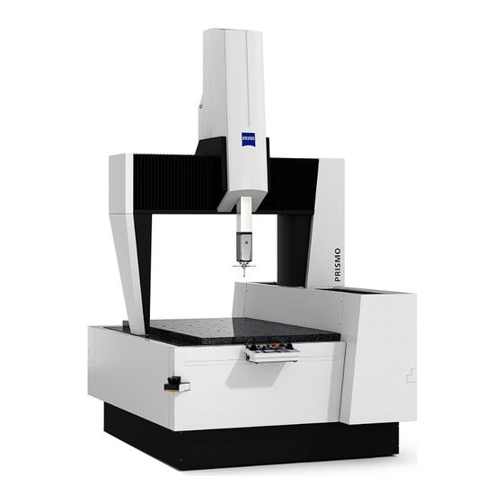
Page 41: Design Of The Cmm
Design of the CMM Design of the CMM A CMM of the PRISMO series is shown below. The CMM types PRISMO 5 and PRISMO 7 are basically identical or the same (in design). The main difference lies in their size. Ram cover... - Page 42 Design of the CMM Different guideway versions are available for PRISMO 10: – X = 1200 mm: guideway on the measuring table – X = 1600 mm: elevated guideway Variant with elevated bridge passage Elevated guideway 61211-1121502 PRISMO...
-
Page 43: Components And Function
Components and function Bridge-type CMM The PRISMO is a bridge-type coordinate measuring machine. The CMM is composed of an X bridge crossbeam and two supports. The X carriage in which the ram is guided moves along the crossbeam. The bridge-type CMM travels in the Y axis. -
Page 44: Measuring Table
NOTE The maximum permissible torque for the threaded bushings is 40 Nm. Measuring volume The measuring volume is the space in which workpieces can be probed. The size of the measuring volume depends on the size of the CMM. 61211-1121502 PRISMO... -
Page 45: Coordinate Axes
The ram is guided in the Z bearing cage. It can be moved in the vertical direction and is used to probe in the Z axis. The probing system is lo- cated at the bottom of the ram. 61211-1121502 PRISMO... -
Page 46: Reference Standard
Type RSH 214 For small to medium sizes with VAST probe RSH 364 For small to medium sizes with RDS probing systems and for large sizes with VAST probe. RSH 514 For large sizes with RDS probing systems. 61211-1121502 PRISMO... -
Page 47: Service Unit For Compressed Air Supply
NOTE The filter is equipped with a water separator. If water has accumulated in the water separator, it can be drained using the push button on the bottom of the filter. 61211-1121502 PRISMO... -
Page 48: Msr Changer Rack
5 Foot profile; consisting of mounting and guide profiles Height and length of the changer rack: Changer rack height 450 - 800 mm Changer rack length 800 - 1600 mm NOTE The height and length of the changer rack depends on the CMM. 3-10 61211-1121502 PRISMO... - Page 49 Y axis and insufficient space is available for this purpose in the X axis. Mounting bracket [1] Frame supports The profile rails are mounted on the frame supports. Spacers are pro- vided for this purpose. 3-11 61211-1121502 PRISMO...
-
Page 50: Control Unit And Operation
32-bit controller. This controller has the designation C99m. NOTE ZEISS USB sticks (backup or boot sticks) may only be used on ZEISS con- trollers and on computers of ZEISS service technicians. We do not as- sume any warranty or liability for damage due to other use. - Page 51 5 Fan; air intake 6 Power supply of the controller cabinet and cables leading to the CMM. NOTE If the MCC 800 is climate-controlled, the air conditioning unit is located on the rear side of the controller cabinet. 3-13 61211-1121502 PRISMO...
-
Page 52: Control Elements On The Mcc 800 Controller Cabinet
Control unit and operation Control elements on the MCC 800 controller cabinet The following control elements and indicator lamps are located on the controller cabinet: Carl Zeiss Industrielle Messtechnik GmbH Carl-Zeiss-Straße 22 73447 Oberkochen Ser.No. xxxxxxx MCC800 / K50 REV 02 620800-9001-250 max.2500VA... - Page 53 This shuts off all drives. The EMERGENCY STOP button must be released before reactivating the drives. Release the button by turning it clockwise. The drives can then be turned on again. For further information See 3-15 61211-1121502 PRISMO...
-
Page 54: Control Console
8 Joystick for the Z axis and the rotary table (optional). The joystick is equipped with a push button to release the rotary table (if available) 9 Control knob for setting the travel speed NOTE There is a separate document for the control console. 3-16 61211-1121502 PRISMO... - Page 55 To reverse the movement direction of the joystick, you need to press a button on the control console. See operating instructions for the con- trol console. NOTE The right joystick is also used control the travel movements of the artic- ulating system. See operating instructions for the control console. 3-17 61211-1121502 PRISMO...
- Page 56 The lock must be released before it will be possible again to carry out travel movements using the joysticks. More information can be found in a separate document. See operating instructions for the control console. 3-18 61211-1121502 PRISMO...
-
Page 57: Probing System
Probing system Probing system Types of probing systems The PRISMO can be equipped with different probing systems. Probing system VAST gold Standard VAST XTR gold Option RDS-D with VAST XXT Option RDS-D with optical probes: ViScan, LineScan, or Option DotScan... - Page 58 Probing system Combination of an RDS articulating system (probe holder) and a probe: RDS-D articulating system Probes with RDS-D: RDS-D / … Probe VAST XXT Application Universal Measuring principle Measuring (discrete point and scanning) 3-20 61211-1121502 PRISMO...
-
Page 59: Optical Probing Systems
The CMM can be equipped with a ROTOS roughness sensor. The ROTOS roughness sensor is inserted into the VAST adapter plate receptacle. For more information, refer to the separate operating instructions for roughness sensors. VAST gold / … Roughness sensor ROTOS 3-21 61211-1121502 PRISMO... -
Page 60: Articulating Stylus
You will find further information on the articulating stylus in the separate operating instructions »Contact probing systems«. Application Flexible use of styli Special feature Continuous swiveling of the stylus. Note: The articulating stylus is available in different versions. 3-22 61211-1121502 PRISMO... -
Page 61: Chapter 4 Technical Data
Technical data Technical data This chapter contains: CMM...................... 4-2 61211-1121502 PRISMO... -
Page 62: Cmm
»Installation site requirements«. General data NOTE The Z measuring range applies to the VAST gold probe. For other probe versions, the Z measuring range varies slightly from the specified values. PRISMO 7/9/Z: Type 7/9/5 7/9/7 Dimensions... - Page 63 2400 [mm] Weight [kg] 2300 2950 3460 4740 Workpiece [kg] 1300 1500 1500 2000 Sound pressure level of the [dBA] <70 PRISMO 12/Y/10: Type 12/18/10 12/24/10 12/30/10 12/42/10 Dimensions Width [mm] 2060 Length [mm] 2950 3550 4150 5350 Height [mm]...
-
Page 64: Characteristic Values Of The Coordinate Measuring Machine
PRISMO 16/Y/10: Type 16/24/10 16/30/10 16/42/10 Dimensions Width [mm] 2460 Length [mm] 3540 4140 5340 Height [mm] 3860 An additional vertical clearance is required for installation work: minimum 200 mm Measuring range [mm] 1600 [mm] 2400 3000 4200 [mm] 1000... -
Page 65: Amount Of Heat Generated
(50 Nl/min at 1 bar) Travel speed Creep speed: SLOW function 0 to 5 mm/s Set-up mode: MAN operating mode 0 to 70 mm/s Series measurement mode: AUTO operating mode Axis max. 300 mm/s Vector max. 520 mm/s 61211-1121502 PRISMO... -
Page 66: Environmental Conditions
– Temperature variations must not exceed certain values. Limit values vary depending on the CMM size. See “Technical specifications”. Limit values for PRISMO 10 (X = 1200 mm): 1.8 K/d and 0.8 K/h. Example for a reference temperature of 20°C:... - Page 67 Temperature Change Status Action Per hour 19.2 - 20.0°C 0.8 K 20.0 - 20.7°C 0.7 K 19.1 - 20.0°C 0.9 K Not OK Wait for 48 hours until the new temperature set is constant. 61211-1121502 PRISMO...
- Page 68 61211-1121502 PRISMO...
-
Page 69: Chapter 5 Transport And Installation
Transport and installation Transport and installation This chapter contains: Notes...................... 5-2 Transport ..................... 5-3 Installation .................... 5-4 61211-1121502 PRISMO... -
Page 70: Notes
This document in- forms you about all measures to be taken for transport and installation. In the following, we will refer to some of the most important points contained in this document. 61211-1121502 PRISMO... -
Page 71: Transport
NOTE The packaging or shipping crates must not be damaged. The packaging may only be removed at the installation site by a ZEISS service techni- cian. Ambient temperature The transport pallets or shipping crates must be stored in a covered area until the machine is installed. -
Page 72: Installation
A vibration analysis should be carried out. The result of the analysis should be made available to ZEISS for planning purposes. An additional foundation may be necessary. NOTE ZEISS can carry out a vibration analysis for you. Please contact us if you need our support. 61211-1121502 PRISMO... -
Page 73: Installation Requirements
Installation Installation requirements The following preparations have to be made prior to the installation of the CMM by a ZEISS service engineer: 1 Provision of steel plates. Steel plates are included in the standard equipment of certain CMMs. 2 Installation of the power supply. - Page 74 Installation 61211-1121502 PRISMO...
- Page 75 Start-up Start-up This chapter contains: Preparations for start-up ................ 6-2 Switching the CMM on ................ 6-12 Preparing the probing system.............. 6-17 Preparing the stylus system ................ 6-21 Setting up the workpiece ................ 6-22 Start-up checklist .................. 6-26 61211-1121502 PRISMO...
-
Page 76: Preparations For Start-Up
The visual check should be part of your daily measuring operation rou- tine. Initial start-up by a service engineer Initial start-up is carried out by a ZEISS service engineer. However, you must familiarize yourself with the preparations required for start-up as well as know and follow the corresponding safety instructions. - Page 77 If the required pressure is no longer indicated, proceed as follows: ➤ 1 Identify the cause of the decrease or increase in pressure. [⇨ 8-3] 2 Call a ZEISS service technician if you cannot find or eliminate the cause. 61211-1121502 PRISMO...
-
Page 78: Setting Up The Msr Changer Rack
Setting up the MSR changer rack Requirements The changer rack is mounted by a ZEISS service engineer during the ini- tial start-up. If the changer rack is to be installed in another location or a second changer rack is to be installed, you have to observe certain points. - Page 79 Preparations for start-up NOTE For the MSR changer rack certain points must be observed: — The changer rack may only be used in connection with ZEISS coordi- nate measuring machines. — Only rack holders approved for use with ZEISS coordinate measuring machines may be mounted.
- Page 80 2 On the opposite side, loosen the set screws on the spacer and the frame support. 1 Set screws on the frame support 2 Set screw on the spacer; here the set screw for fastening the profile rail 3 Direction of movement when moving the second foot profile. 61211-1121502 PRISMO...
- Page 81 The height of the lower profile rail can be adjusted. Proceed as follows: 1 Loosen the set screw on both spacer bolts. 1 Set screw on the spacer bolt; here the set screw for fastening on the frame sup- ports. 61211-1121502 PRISMO...
- Page 82 The cross-piece remains in the spacer bolt. 4 Slide both tension rods into the groove of the profile rail and turn by 90°. 5 Fasten the profile rail on the spacer bolt. — Slide the tension rod completely into the spacer bolt. 61211-1121502 PRISMO...
- Page 83 The minimum distance between two holders must be 150 mm. Example of how to mount a holder for the VAST adapter plates: A Cap B VAST holder; top view C VAST holder; front view 1 Slot nut 2 Screw; M6 x16 61211-1121502 PRISMO...
- Page 84 Qualify all holders on the profile rail. Position of the changer rack was changed. Qualify all holders on the changer rack. For more information on qualification, please refer to the operating in- structions for the measuring software. 6-10 61211-1121502 PRISMO...
-
Page 85: Visual Check And Checklist
1 In this case, protect the CMM against switching on: — Switch off the main switch and lock it with a padlock. 2 Inform the ZEISS service department. Covers The CMM may only be operated if all covers are mounted on the CMM and all doors are closed. -
Page 86: Switching The Cmm On
– The default speed in the measuring software is reduced. – There is an object or a person in the laser scanner's protected area (the scanner LED lights up red). Measuring software NOTE The probe must be connected to the ram before starting the measuring software. 6-12 61211-1121502 PRISMO... -
Page 87: Cmm Starting Sequence
The power supply for all electronic components on the CMM is on. Switching the controller on [2] The controller is switched on via the control console. For this purpose, a push button is located on the left side of the control console. 6-13 61211-1121502 PRISMO... - Page 88 The boot process must finish be- fore the drives can be turned on. The LED above the button for the drives flashes during the booting process. In addition, the ZEISS logo moves over the display.
- Page 89 The boot process must finish be- fore the drives can be turned on. The LED above the button for the drives flashes during the booting process. In addition, the ZEISS logo moves over the display.
- Page 90 – Turn the key switch (optional) to the required position. Note: Information on the operating modes: see above. Turn on the computer 1 Turn on the computer and peripheral devices, e.g. a printer. The computer boots and the operating system starts. 2 Start the measuring software. 6-16 61211-1121502 PRISMO...
-
Page 91: Preparing The Probing System
7 Hexagon socket screw, width across flats: 2,5 mm 1 Move the ram to a position from which the articulating head can be attached to the ram. Use the joysticks on the control console to move the CMM in all axes. 6-17 61211-1121502 PRISMO... - Page 92 Use the joysticks on the control console to move the CMM in all axes. 2 Switch the drives off. 3 Slide the probe onto the dovetail guide of the ram up to the stop. 6-18 61211-1121502 PRISMO...
-
Page 93: Replacing A Probe With An Articulating Head
5 Remove the VAST probe from the dovetail guide of the ram [4]. 6 Slide the RDS articulating head onto the dovetail guide (withoutRDS adapter plate) [5 ]. 7 Tighten the screw to 2.2 Nm [6]. 8 Reactivate the drives. 6-19 61211-1121502 PRISMO... - Page 94 The new probing system is automatically recognized. However, it must be initialized in the measuring software. Then the styli of the stylus sys- tem must be qualified and the workpiece must be aligned again during the computer-controlled manual run See operating instructions for the measuring software. 6-20 61211-1121502 PRISMO...
-
Page 95: Preparing The Stylus System
Preparing the stylus system Preparing the stylus system For information on the stylus system, please refer to the separate brochure »Sensors«. Automatic stylus system change ➤ Notes on the automatic change: See [⇨ 7-4]. 6-21 61211-1121502 PRISMO... -
Page 96: Setting Up The Workpiece
— Clean the workpiece and the measuring table before placing a workpiece on the measuring table. — Remove any greasy or oily substances from the measuring table and the workpiece. 6-22 61211-1121502 PRISMO... -
Page 97: Precautionary Measures
2 mm/s. The CMM may be damaged if the workpiece is set down abruptly. 5 Put the workpiece down vertically on the measuring table. 6 Do not move the workpiece on the measuring table. 6-23 61211-1121502 PRISMO... -
Page 98: Procedure
Position the workpiece so that all required measurements can be carried out without changing the workpiece position. Measuring operation When using a changer rack, position the workpiece so that the measure- ment and the stylus system change can be carried out without collision. without collision 6-24 61211-1121502 PRISMO... - Page 99 NOTE Large and bulky workpieces may project over the measuring volume as long as the travel movements are not hindered. This is an exception which requires the approval of ZEISS. Clamping the workpiece Workpieces must always be clamped. – Clamp all workpieces securely in place.
-
Page 100: Start-Up Checklist
– Is the workpiece in the correct position? See [⇨ 6-24] – Is it possible to measure all workpiece dimensions in one cycle? – Is measurement possible without collision? A collision with the changer rack, for example. – Has the workpiece been clamped properly? 6-26 61211-1121502 PRISMO... - Page 101 Measuring operation Measuring operation This chapter contains: What you should know!................ 7-2 Safety during the measuring operation............ 7-5 Preparation for measuring operation............ 7-9 Probing the workpiece ................ 7-20 Evaluation of the measured results ............. 7-23 Terminating the measuring operation............ 7-25 61211-1121502 PRISMO...
-
Page 102: What You Should Know
The AUTO operating mode may only be selected for measurement runs tested previously. PowerSaver / AirSaver function PowerSaver (previous name: AirSaver) is a function for saving com- pressed air. For more information, please refer to the separate AirSaver (PowerSaver) operating instructions. 61211-1121502 PRISMO... -
Page 103: Coordinate Systems
Clamp a workpiece before probing. Otherwise, the workpiece may be shifted by the probing. Correct measurement is not possible if the work- piece is shifted. NOTE In the ideal case, probings should be performed perpendicular to the probing surface. 61211-1121502 PRISMO... -
Page 104: Tip For Effective Work
A specific holder in the changer rack must be allocated to each stylus system. You should note which rack holder is allocated to which sty- lus system. NOTE The measuring software is required in order to carry out this procedure. Please refer to the operating instructions for the measuring software. 61211-1121502 PRISMO... -
Page 105: Safety During The Measuring Operation
— Reduce the maximum travel speed either via the control knob on the control console or in the measuring software. — Always keep the control console within reach in order to be able to press the EMERGENCY STOP button in case of emergency. 61211-1121502 PRISMO... - Page 106 Electromagnetic fields CAUTION Impairment of the function of electronic components due to electromagnetic fields. The function of active implants may be impaired. — Keep a minimum distance of 100 mm from the VAST probe or an- other magnetic source. 61211-1121502 PRISMO...
-
Page 107: Precautions
Collision between the ViScan and the DotScan light guide due to a large pivoting angle. Damage to the light guide. ü The pivoting angle must be in the range of ±130°. — Make sure that the swiveling range is within the specified limits. 61211-1121502 PRISMO... - Page 108 OFF automatically! – All existing safety equipment must be used. Make sure that no one is in the danger zone. – For more information on the safety equipment, please refer to the separate »Installation site requirements« brochure. 61211-1121502 PRISMO...
-
Page 109: Preparation For Measuring Operation
It is located in the upper left corner of the measuring range. The reference point must be determined by a reference point travel prior to the measuring run. 1 Reference point (= origin of the machine coordinate system) 2 Park position, signs of the coordinates: +X, -Y and -Z 61211-1121502 PRISMO... - Page 110 — To avoid collisions, move the RDS to the 0°/0° position. Starting the automatic run The homing run is started by the measuring software. Please refer to the operating instructions for the measuring software. 7-10 61211-1121502 PRISMO...
-
Page 111: Stylus System Qualification
– When inserting a new stylus into the stylus system. – When mounting a new probe. What should be observed during qualification? Take the following steps during qualification: – Perform a reference measurement; use a master stylus. – Select the stylus to be qualified. 7-11 61211-1121502 PRISMO... - Page 112 – The limit values for assembly of the stylus system have been ob- served. – The reference sphere, the stylus tips, and the adapter plate are clean and not damaged. – The stylus system components are intact. 7-12 61211-1121502 PRISMO...
- Page 113 1 Vertical orientation of the reference sphere Performing a reference measurement The position of the reference sphere must be determined before the sty- lus vector can be determined. Use the master stylus for this purpose. Proceed as follows: 7-13 61211-1121502 PRISMO...
- Page 114 2 Probing direction 3 Reference sphere; probing on the pole. 5 Remove the master stylus. All styli can now be qualified. Qualification procedure After the reference measurement has been carried out, the stylus sys- tems can be qualified. 7-14 61211-1121502 PRISMO...
- Page 115 4 Probe the reference sphere in the shaft direction of the stylus and measure its diameter. The shaft of the reference sphere may not be probed during the qualification. Probing directions during qualification A Correct B Incorrect 1 Stylus shaft 2 Probing direction 7-15 61211-1121502 PRISMO...
- Page 116 Sources of errors The sources of malfunctions and errors which may lead to increased de- viations are listed below. – Stylus system configuration – Stylus status – Magnetic field – Influence of temperature 7-16 61211-1121502 PRISMO...
-
Page 117: Temperature Compensation
Case 2: Connecting a temperature sensor to the CMM is possi- ble. 1. Enter the expansion coefficient for the workpiece ma- terial in the measuring software. 2. Connect the temperature sensor. The measuring software calculates the correction value. 7-17 61211-1121502 PRISMO... - Page 118 – You should also carry out test measurements when the CMM has been in operation for several weeks. In case of constant ambient conditions, one test measurement per week is sufficient. In case of varying ambient temperatures, test measurements should be carried out more frequently. 7-18 61211-1121502 PRISMO...
- Page 119 1 Plug the connector into the connection sockets. The connection sockets are located on the rear side of the CMM. Two sockets are available. 2 Place the copper blocks at two different locations in or on the work- piece to be measured. 7-19 61211-1121502 PRISMO...
-
Page 120: Probing The Workpiece
The travel speed depends on the deflection of the joystick. At the begin- ning and end of the deflection range, the travel speed is proportional to the amount of deflection. The travel speed between the beginning and the end is constant. This speed corresponds to the probing speed. 7-20 61211-1121502 PRISMO... - Page 121 When probing oblique workpiece surfaces at an angle between 30° and 50°, the probing speed should be reduced. Particularities of probing systems For the various probing systems, certain points must be observed: For more information, please refer to the separate brochure »Sensors«. 7-21 61211-1121502 PRISMO...
-
Page 122: Preventing Measuring Errors
Has the reference measurement been carried out? Has the qualification been carried out correctly? When using a measuring probing system, has tensor quali- fication been performed? All styli qualified? Has the correct stylus been selected? Has the temperature compensation been carried out? 7-22 61211-1121502 PRISMO... -
Page 123: Evaluation Of The Measured Results
– The structure of the stylus system is not stable. – The stylus system components are not screwed together firmly enough. – Admissible probe limiting values have not been observed. The stylus system is too long, too heavy or contains components which are not suitable. 7-23 61211-1121502 PRISMO... - Page 124 – Different axis clamping set than for qualification. – Different measuring force set than for qualification (depending on the measuring method, with measuring probes) Probing – Probing has not been performed perpendicular to the probing sur- face. 7-24 61211-1121502 PRISMO...
-
Page 125: Terminating The Measuring Operation
The drives are off when the LED above the button is not lit. 7 Switch the controller off. Controller shutdown is complete once the control console display is off. 8 Switch off the power supply. — Turn the main switch counterclockwise to position «0». 7-25 61211-1121502 PRISMO... - Page 126 Terminating the measuring operation 7-26 61211-1121502 PRISMO...
- Page 127 Errors and faults Errors and faults This chapter contains: Errors occurring prior to measuring operations.......... 8-2 Malfunctions during measuring operations........... 8-3 Special measures.................. 8-5 Service features.................. 8-18 61211-1121502 PRISMO...
-
Page 128: Errors Occurring Prior To Measuring Operations
1 If the above mentioned errors can be excluded, put the CMM out of operation and repeat the start-up procedure. 2 If measuring operation is still not possible, call a ZEISS service techni- ➤ cian or our support team. -
Page 129: Malfunctions During Measuring Operations
The probe is outside Return the probe to the measur- ➤ the measuring vol- ing volume. See [⇨ 8-6]. ume in the X or Y axis. 61211-1121502 PRISMO... - Page 130 – Reduce the pressure in the air Indicating instru- the air bear- high. supply line. ments ings. – Call a ZEISS service technician. Travel move- The set travel speed is Increase the travel speed: ment too slow. too low. – Turn the control knob on the control console clockwise.
-
Page 131: Special Measures
If the ram or the probe collides with an obstacle, the guideway and other components of the CMM may become damaged. In this case, perfect measuring operation is no longer guaranteed. If measurements are not possible after a collision, call a ZEISS service technician or our support. NOTE After a collision, the stylus system has to be requalified and the work- piece position (W position) has to be determined again. -
Page 132: Probe Outside The Measuring Volume
NOTICE! You may only push against the right column of the bridge (drive side). Do not push against the probe and do not push against the left-hand column of the bridge. 61211-1121502 PRISMO... -
Page 133: In Case Of Air Conditioning Failure
1 Slowly adjust the temperature to the nominal value. The temperature gradient should be about 1 K per hour. Larger gra- dients may cause material deformations, thus leading to permanent deformation of the CMM guideways. 61211-1121502 PRISMO... -
Page 134: Contamination Of Dotscan Fiber Optic Cable
One-Click Cleaner. The One-Click Cleaner is included in the delivery package. NOTE If the fiber optic cables are contaminated, the measuring software can- not collect any data. In this case, an error message is displayed. The fiber optic cables then must be cleaned. 61211-1121502 PRISMO... - Page 135 Requirements for the exposure times: Minimum values Typical values ACCURA ≥ 7 ms 9 - 10 ms PRISMO ≥ 6 ms 7 - 8 ms NOTE No workpieces may be located in the measuring range when perform- ing the dark balance.
- Page 136 1 Press the unlocking lever on the connector. [1] 2 Pull the connector out of the FOC coupling. [2] Cleaning the fiber optic cable in the FOC connector A Connector B Tool for opening the connector C Mounted tool 8-10 61211-1121502 PRISMO...
- Page 137 2 Insert the tip of the One-Click Cleaner in the FOC coupling on the ram and press the One-Click Cleaner once (1×). [2] 3 Plug the cleaned FOC connector into the cleaned FOC coupling on the ram. 8-11 61211-1121502 PRISMO...
- Page 138 FOC coupling on the ram. Removing the left connector Coupling point (left) 1 Press the unlocking lever on the connector. [1] 2 Pull the connector out of the FOC coupling. [2] 8-12 61211-1121502 PRISMO...
- Page 139 3 Remove the One-Click Cleaner from the connector and close the cap on the protective sleeve. 4 Remove the tool from the connector. Note: Do not plug the FOC coupling back in immediately. Clean the fiber optic cable on the right side first. 8-13 61211-1121502 PRISMO...
- Page 140 B Tool C Tool on FOC connector holder D Pulling out the connector holder 1 Slide the tool onto the FOC connector holder. [B,C,1] 2 Pull the FOC connector holder in the direction of the arrow. [D,2] 8-14 61211-1121502 PRISMO...
- Page 141 4 Remove the One-Click Cleaner from the connector and close the cap on the protective sleeve. 5 Remove the tool from the connector. NOTE If the fiber optic cables of both FOC connectors have been cleaned, the connectors can be plugged back into the coupling. 8-15 61211-1121502 PRISMO...
- Page 142 Connector on RDS 2 Plug the connector holder into the coupling holder on the right side. [2, bottom] Note: The “TOP” label must face upwards. [1, bottom] Condition after mounting: The fiber optic cables of all connectors have been cleaned. 8-16 61211-1121502 PRISMO...
- Page 143 Special measures NOTE Next, a dark balance must be performed again and the exposure time must be checked. Please refer to ➤ Fault rectification procedure [⇨ 8-9] and the operating instructions for the measuring software. 8-17 61211-1121502 PRISMO...
-
Page 144: Service Features
Within Germany: 0 73 64.20.6337 From abroad: +49.73 64.20.6337 Teleservice ZEISS offers fast and economical help in the form of online diagnostic tools. There are several options here. Teleservice tools – Online diagnosis of errors – Online software update – Online service –... -
Page 145: Chapter 9 Maintenance And Care
Maintenance and care Maintenance and care This chapter contains: Maintenance.................... 9-2 Care...................... 9-4 61211-1121502 PRISMO... -
Page 146: Maintenance
These persons must have received special training on the corresponding CMM qualifying them to carry out all necessary maintenance work. Maintenance agreement ZEISS offers maintenance agreements relieving you of any need to worry about maintenance. NOTE If you wish to subsequently conclude a maintenance agreement, call our support. - Page 147 Measuring system For example functioning, precision Controller For example operator's controls; control console Drive unit Motor and gear unit Sensors Probing system NOTE When concluding a maintenance agreement, you also must specify any optional equipment to be covered. 61211-1121502 PRISMO...
-
Page 148: Care
The measures for care also include the regular cleaning and checking of certain components. Cleaning agent: Agent Purpose Mild cleaning agent Lint-free cloth, for example made of linen Vacuum Solvent To remove aluminum build-up from the stylus tip 61211-1121502 PRISMO... -
Page 149: Safety Instructions
Preventive care also includes making sure that all workpieces to be mea- sured are clean. The workpieces must be free from machining residues (e.g. metal chips, oil) and dust. — Clean the workpieces before placing them on the measuring table. 61211-1121502 PRISMO... -
Page 150: Overview
At least every week Lint-free cloth; use a See [⇨ 9-11] cleaning agent if re- quired ➤ Filter mat for ventilation of Quarterly – Clean by beating and See [⇨ 9-11] the controller cabinet vacuuming – Replace the filter if re- quired 61211-1121502 PRISMO... -
Page 151: Care And Cleaning
— Clean the guideway every day or, if necessary, more frequently. Threaded bushings Dust may accumulate in the threaded bushings and threads. To ensure perfect condition of the threads, remove any dirt deposits from the threaded bushings with a vacuum cleaner. 61211-1121502 PRISMO... - Page 152 The reference sphere must be clean and undamaged to ensure correct qualification. – Clean the reference sphere with a lint-free cloth. – Use a cleaning agent if necessary. Ensure that there is no cleaning agent residue on the reference sphere. 61211-1121502 PRISMO...
- Page 153 Make sure that the adapter plate receptacle is free from cleaning agent residues. This could impair the function of the adapter plate receptacle. ViScan Light fixture and lens must be free from dirt particles and streaks. – Clean the glass surfaces with a dry, lint-free cloth or a brush. 61211-1121502 PRISMO...
- Page 154 Vacuum the covers and clean them with a damp cloth. NOTE The covers must not be removed. Safety laser scanner The radiation exit window may get dirty over time and impair the laser scanner function. – Clean the exit window with a damp cloth. 9-10 61211-1121502 PRISMO...
-
Page 155: Inspection Measures
3 Air filters of the fans 1 Remove the air filter cover. 2 Clean or replace the filter mat. The fins of the air filter cover must be inclined downwards. See illus- tration. 3 Place the cover on the air filter. 9-11 61211-1121502 PRISMO... - Page 156 If one of the filter elements significantly changes color before ex- piry of this interval, you should replace the filter elements. To order the filter elements, please call the support team or contact a ZEISS service engineer. Different filter elements are used in the filters:...
- Page 157 — Make sure to depressurize the line. 1 Open the filter cap and remove it. 2 Clean the filter cap. 3 Replace the filter element. 4 Reattach the filter cap. After replacing the filters, the compressed air can be switched on again. 9-13 61211-1121502 PRISMO...
- Page 158 Care 9-14 61211-1121502 PRISMO...
-
Page 159: Chapter 10 Shutdown And Disposal
Shutdown and disposal Shutdown and disposal This chapter contains: Decommissioning .................. 10-2 Disposal ..................... 10-3 10-1 61211-1121502 PRISMO... -
Page 160: Decommissioning
2 Store the CMM in a dust-protected place. — Read and follow the instructions regarding transport in the sepa- rate publication »Installation site requirements«. NOTE In addition, we recommend covering the CMM, e.g. by means of a tar- paulin. 10-2 61211-1121502 PRISMO... -
Page 161: Disposal
Category 9 (WEEE) All ZEISS IMT products including goods such as TSK and OEM products sold by us and bearing the ZEISS logo are assigned to Category 9 of the Appendix of the WEEE directive. All ZEISS IMT products comply with the RoHS directive unless they are subject to a specific exemption. - Page 162 – Please contact your dealer or supplier regarding the disposal of elec- trical and electronic devices. Outside the European Union: – Make sure to comply with the corresponding laws and other local regulations regarding the disposal of electrical and electronic de- vices. 10-4 61211-1121502 PRISMO...
- Page 163 Examples: Sphere, cylinder, disk. VAST Abbreviation for »Variable Accuracy and Speed Probing Technology« WEEE Acronym for »Waste Electrical and Electronic Equipment«; EU Directive on Waste Electrical and Electronic Equipment Acronym for »ZEISS Articulating Stylus« 61211-1121502 PRISMO Glossary...
- Page 164 61211-1121502 PRISMO Glossary...
- Page 165 Qualification of the holders 6-10 MCC 800 3-14 Requirements 6-4 Controller Characteristic values 4-4 Checklist Switching on 6-13, 6-15 Measuring errors 7-22 Controller cabinet 3-12 Control elements 3-14 Start-up 6-26 Ingress protection rating 3-12 Clamping equipment 6-25 Main switch 3-15 Replacing the filter mat (MCC 800) 9-11 Type plate 3-12, 3-14 61211-1121502 PRISMO Alphabetic index...
- Page 166 Error sources Protective field 2-17 Errors occurring prior to measuring Review 2-20 operations 8-2 LineScan Malfunctions during measuring Care 9-10 operations 8-3 Safety instructions 2-13 Expansion coefficient 7-17 Liquid 7-7 Exposure time 8-9 Magnetic parts 7-7 Fall brake Main switch 3-15 Releasing 8-7 Fiber optic cable Cleaning 8-8 Exposure time 8-9 61211-1121502 PRISMO Alphabetic index...
- Page 167 Qualification Measuring force 7-8 Performing 7-14 One-Click Cleaner 8-8 Preparation 7-12 Operating mode 7-2 Requirements 7-12 Key switch 3-14 Sources of errors 7-16 Selection 6-14, 6-16 Tensor qualification 7-15 Operating position 3-17 What to observe? 7-11 Overvoltage category 4-4 When to qualify? 7-11 Why is qualification necessary? 7-11 Park position 7-9, 7-11 61211-1121502 PRISMO Alphabetic index...
- Page 168 Connecting the temperature sensors 7-19 Safety laser scanner Correction value 7-17 Review 2-20 Temperature control 5-5 Scattering Temperature sensor 7-17, 7-19 Causes 7-23 Tensor qualification 7-15 Serial number 3-2 Transport Series 3-2 Forklift, requirements 5-3 Service unit 3-9 Travel speed Setting up the workpiece Set-up mode 4-5 Procedure 6-24 61211-1121502 PRISMO Alphabetic index...
- Page 169 Fastening 6-18 Vibration analysis 5-4 Vibrations 7-8 ViScan Care 9-9 ViScan optical probe Safety instructions 2-13 Visual check 6-11 Warranty 1-6, 2-2 WEEE 10-3 Workpiece Clamping equipment 6-25 Expansion coefficient 7-17 Heavy workpieces 6-24 Positioning 6-24 Putting down on the measuring table 6-24 X carriage 3-3 Year of manufacture 3-2 ZAS 3-22 61211-1121502 PRISMO Alphabetic index...
- Page 170 61211-1121502 PRISMO Alphabetic index...
- Page 172 PRISMO Operating Instructions 2022-12-23 61211-1121502...
Need help?
Do you have a question about the PRISMO and is the answer not in the manual?
Questions and answers