Table of Contents
Advertisement
Advertisement
Table of Contents

Related Manuals for Zeiss Gom T-SCAN hawk


Summary of Contents for Zeiss Gom T-SCAN hawk
- Page 1 Precise Industrial 3D Metrology Hardware User Manual T-SCAN hawk...
-
Page 2: Legal Notes
Legal Notes No part of this publication may be reproduced in any form or by any means or used to make any derivative work (such as translations, transfor‐ mations or adaptations) without the prior written permission of GOM. GOM reserves the right to revise this publication and change contents from time to time without obligation on the part of GOM to provide noti‐... -
Page 3: Table Of Contents
Table of Contents Legal Notes............2 Calibrate the Sensor......... 14 When is Calibration Necessary?.... 14 Important Notes...........5 Calibrating Sensor with Calibration Standard Signal Words.......5 Panel............. 15 Safety and Health Hazard Notes....5 Calibration Result........16 Introduction...........7 Cabling............ - Page 4 0000001879_002_EN_30-09-2020 Page 4 (19)
-
Page 5: Important Notes
Important Notes Standard Signal Words In this publication the following standard signal words can be used: DANGER ▶ The label points to an imminent danger. The situation can lead to seri‐ ous bodily harm or death! WARNING ▶ The label points to a dangerous situation. The situation can lead to serious bodily harm or death! CAUTION ▶... - Page 6 Important Notes WARNING Repair work Repair work can cause serious bodily harm and considerable material damage. ▶ Only authorized and qualified service personnel is allowed to perform repair work! ▶ Always comply with the accident prevention regulations! CAUTION The local supply voltage must be within the operating voltage range of the device! An incorrect operating voltage can cause malfunctions or the risk of fire.
-
Page 7: Introduction
Introduction This manual is intended for qualified personnel who do not have any or only few experiences with coordinate measuring technology. Basic PC knowledge (windows-based programs and operating systems) is expec‐ ted. For operating the system optimally, the ability to visualize in 3D and a color vision ability are assumed. -
Page 8: Product Description
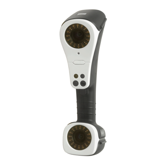
Product Description The T-SCAN hawk sensor (Fig. 1) is a high-resolution 3D scanner that sup‐ plies fast and accurate three-dimensional measuring data. The T-SCAN hawk comprises multiple line lasers. Using its stereo camera setup, the T- SCAN hawk sensor records spatial 3D point clouds on the surface of the measuring object. -
Page 9: System Overview
System Overview Technical Data System T-SCAN hawk Scan mode Default Single-line Fine Laser source 7 intersecting 1 red laser line 5 parallel blue red laser lines laser lines Resolution 0.050 mm 0.050 mm 0.010 mm Scan area max. 550 x 600 mm Scan details Supported Deep recesses... -
Page 10: Information About The Sensor
Information About the Sensor Each configured sensor, in scan direction, has defined 3D areas within which a measuring object can be scanned. In the following, such a 3D area is called “measuring volume” (MV). Sensor Configurations Measuring Areas T-SCAN hawk Measuring Mode Blue Lasers Red Lasers... - Page 11 Information About the Sensor Resolution Red Measuring Area Blue Measuring Area Measuring Height Measuring Height Distance A2 (Measuring Distance A1 (Measuring [mm] Volume) B2 [mm] Volume) B1 [mm] [mm] 0.01–0.1 0.1–1 > 1 Tab. 1: T-SCAN hawk measuring areas Info The optimal distance for Photogrammetry A3 is always 2 m.
-
Page 12: Control Elements And Led Indicators
Control Elements and LED Indicators Fig. 3: Front and rear control elements Camera A Control buttons, rear Laser aperture Indicator light Control button, front USB cable, power Camera B USB cable, data connection Indicator light 0000001879_002_EN_30-09-2020 Page 12 (19) - Page 13 Control Elements and LED Indicators Fig. 4: Front and rear control buttons Initiate photogrammetry Zoom out/reduce exposure measurement time/previous step in work‐ Zoom in/increase exposure flow time/next step in workflow Start action/switch between Change control mode red/blue laser 0000001879_002_EN_30-09-2020 Page 13 (19)
-
Page 14: Calibrate The Sensor
Calibrate the Sensor Calibration is a measuring procedure in which a calibration object is meas‐ ured. This configures the measuring system and ensures its dimensional accuracy. During this process, the software determines geometric parame‐ ters, e.g., the position and orientation of each camera, based on recorded camera images. -
Page 15: Calibrating Sensor With Calibration Panel
Calibrate the Sensor Calibrating Sensor with Calibration Panel Requirements: The sensor is set up. • The calibration object is on a solid surface. • Procedure: 1. Open the calibration dialog in the workspace T-SCAN hawk with Calibrate Sensor ► a) The software then opens the calibration dialog. Fig. -
Page 16: Calibration Result
Calibrate the Sensor Fig. 7: Calibration Position 2 First, record various vertical positions on the calibration object. Then, dif‐ ference 45° scanning positions are necessary. The two indicators show the correct position of the sensor. Fig. 8: Other calibration positions Follow the remaining instructions on the software until the procedure is complete. - Page 17 Calibrate the Sensor Info During calibration, make sure no other single point markers affect the pro‐ cedure. Only use the calibration object. Make sure there are no other highly reflec‐ tive objects near the calibration objects. When not calibrating, keep the calibration object in the protective sleeve. After calibration, close the dialog.
-
Page 18: Cabling
Cabling Cabling with Laptop Fig. 10: Connecting T-SCAN hawk to a laptop 0000001879_002_EN_30-09-2020 Page 18 (19) -
Page 19: Declaration Of Conformity
Declaration of Conformity T-SCAN hawk Declaration of Conformity 0000001879_002_EN_30-09-2020 Page 19 (19)
Need help?
Do you have a question about the Gom T-SCAN hawk and is the answer not in the manual?
Questions and answers