Table of Contents
Advertisement
Advertisement
Chapters
Table of Contents

Related Manuals for Zeiss VISUREF 150


Summary of Contents for Zeiss VISUREF 150
- Page 1 ZEISS VISUREF 150 Autorefractor/Keratometer Documentation set...
- Page 2 The weblinks are dynamic hyperlinks. Before incorporating any links, Carl Zeiss Meditec AG checks their content to ensure that it is not likely to result in civil or criminal liability. It does not, however, continuously check for any changes which could form the basis for liability.
- Page 3 Contents User manual ZEISS VISUREF 150 Autorefractor/Keratometer [000000-2227-967-GA-GB-281021] 000000-2227-967-Inhalt0-GB-281021...
- Page 5 ZEISS VISUREF 150 Autorefractor/Keratometer User manual...
- Page 6 000000-2227-967-GA-GB-281021...
-
Page 7: Table Of Contents
Contents Contents Contents ..................1 Notes on the user manual ............4 Purpose and availability of the documentation ..........4 Questions and comments ................4 Explanation of symbols used ................5 Package check list ..............6 Country-specific information and labels ........7 Classification/Manufacturer's declaration ............ - Page 8 Contents Connection to ZEISS FORUM ................31 Connection to ZEISS VISUCONSULT/i.Com mobile ..........33 Provision of data to be collected via the network (web service) ......34 Daily startup ................35 Switching on ....................36 Operation of the device ............37 Warning and information messages ............
-
Page 9: Contents
Contents Shutting down................ 103 Switching off the device ................103 Maintenance and care ............104 Troubleshooting ..................104 Update device software ................105 Replacing the fuses ..................106 Maintenance ....................107 Replacing the printer paper roll ................107 Care and cleaning....................108 Cleaning and disinfection of painted surfaces ............ -
Page 10: Notes On The User Manual
Questions and comments If you have any questions or comments concerning this user manual or the device, please contact ZEISS service or your local dealer. (Contact details see reverse.) 000000-2227-967-GA-GB-281021... -
Page 11: Explanation Of Symbols Used
Notes on the user manual Explanation of symbols used The symbols used in this user manual refer to important safety information which may warn against possible health risks or fatal injuries and contain useful notes. Whenever you see these symbols, read the accompanying information carefully and observe all safety notes and information in this user manual and on device labels. -
Page 12: Package Check List
Package check list Package check list The ZEISS VISUREF 150 basic device is supplied with the parts shown in the following figure. 1 Power supply cable 2 Test eye (also used as contact lens holder) 3 Printer paper (1 roll installed when delivered) -
Page 13: Country-Specific Information And Labels
Country-specific information and labels Country-specific information and labels Classification/Manufacturer's declaration WARNING - GENERAL HAZARD This device may be set up, operated and used only for the intended use and in accordance with local country-specific regulations, generally accepted engineering standards and occupational safety and accident prevention regulations. -
Page 14: Intended Use
Country-specific information and labels Intended use The ZEISS VISUREF 150 Autorefractor/Keratometer is a diagnostic device used to determine the objective refractive values and keratometric characteristics of the human eye. The results are used to assist the process of prescribing optical aids such as eyeglasses and contact lenses. -
Page 15: Intended User Profile
Country-specific information and labels Intended user profile CAUTION - RISK ARISING FROM OPERATING ERRORS This device may only be installed, operated, used and maintained by persons who have been properly trained or who have the required knowledge and experience to do so. Please also adhere to the national qualification guidelines applicable in your country. -
Page 16: Disposal Of The Product
Country-specific information and labels Disposal of the product CAUTION - RISK OF ENVIRONMENTAL POLLUTION The packing material should be kept to be used for a future move or for repairs. If you want to dispose of the packing material, please use a recognized collection system for recycling. -
Page 17: External Labels
Country-specific information and labels External labels 14 4 1 6 5 17 12 13 Fig. 2 External labels 000000-2227-967-GA-GB-281021... - Page 18 Country-specific information and labels Pos. Label Explanation ZEISS VISUREF 150 type label Manufacturer Date of manufacture Applied part type B Identification label with unique device identification code VISUREF 150 Catalogue number/part number Serial number UDI: Unique device identification code (data matrix and plain text)
- Page 19 Country-specific information and labels Pos. Label Explanation Warning label "Avoid contact with the hand" Country of origin label Label with fuse specifications Information label "Disconnect device from the power supply before opening" Not applicable Not applicable Applied part type B Applied part type B Not applicable Not applicable...
-
Page 20: Performance Specifications
ZEISS VISUREF 150 is an autorefractor/keratometer. It allows the measurement of objective refraction including sphere, cylinder, axis. The VISUREF 150 covers the refractive measurement range from -25 D to +22 D so that even patients with severe refractive errors can be measured. -
Page 21: Service Life
By default, the device supports the ZEISS VISUCONSULT/i.Com mobile application and ZEISS FORUM. Thus, the data of the patient to be measured can be retrieved from a worklist and his/her measurement data transferred back to the patient database after measurement. -
Page 22: Description Of The Device
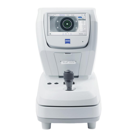
Description of the device Description of the device 1 Status LED (illuminated: device switched on; flashing: screen saver activated) 2 LCD monitor 3 Printer cover 4 Stage locking lever 5 Buttons for chin rest height adjustment 6 Measuring button to trigger the measurement 7 Joystick Fig. -
Page 23: Fig. 4 Patient's Side Of The Device
Description of the device 1 Forehead rest 2 Measurement window 3 Dust cap 4 Chin rest 5 Fixing pins for chin rest paper 6 Canthus markers (Reference mark for optimum eye level of patient) Fig. 4 Patient's side of the device 000000-2227-967-GA-GB-281021... -
Page 24: Fig. 5 Bottom Side View
Description of the device 1 Clamping screw to lock the stage for transportation 2 Fuses 3 Power input socket 4 Monitor output 5 USB port with cover 6 Power switch 7 RS232 interface 8 Network connection (LAN) Fig. 5 Bottom side view 000000-2227-967-GA-GB-281021... -
Page 25: Installation
Installation Installation Notes on installation and use WARNING - GENERAL HAZARD Do not store or operate the device in ambient conditions other than those specified (see Section Technical data on page 113 and following). The device should be set up so that the power cable can be disconnected from the power supply quickly and easily without any tools. -
Page 26: Installing The Device
Installation Installing the device CAUTION - DANGER FROM FALLING PARTS Install the device on a suitable, level, steady table that is not exposed to vibration. When transporting outside the premises, always use the transport packaging. Set up the device so that no light sources (ceiling lamps, spots, ... -
Page 27: Connecting The Device
Installation Connecting the device WARNING - GENERAL HAZARD When connecting the device to a power supply grid, pay attention to the data on the type label. WARNING - RISK OF ELECTRIC SHOCK Be sure to turn off the power switch before connecting to or disconnecting the device from a power supply grid. -
Page 28: Connecting The Device With Other Devices
Please observe that local laws take priority over the above-mentioned requirements. If in doubt, consult your local representative or ZEISS Service. WARNING - RISK OF ELECTRIC SHOCK... - Page 29 Installation WARNING - RISK OF ELECTRIC SHOCK If a non-medical grade LCD Monitor or PC is connected to the autorefractor/keratometer system, the autorefractor/keratometer system must not contact the patient. Relevant standards for non-medical electrical equipment may require chassis leakage current limits which are higher than that required by medical standards.
-
Page 30: Patient Environment
1 Peripheral equipment (EN XXXXX and IEC XXXXX) 2 Peripheral equipment (EN XXXXX and IEC XXXXX) 3 ZEISS VISUREF 150 device 4 Patient environment (represented by dotted line, within a radius of 1.5 meter) 5 Power cable with protective grounding 6 Protective grounding Fig. -
Page 31: Network Configuration
Network configuration WARNING - GENERAL HAZARD Connecting ZEISS VISUREF 150 to an IT network may result in hazards for the patient, operator or a third person or may impair functioning of the device or other participants in the network due to coupling. These hazards or impairments are not within area of responsibility of ZEISS. -
Page 32: Data Exchange
Installation The use of a closed network is recommended, if necessary with a single point of access to connect to other networks. The exact specification of the network, including the required safety devices, depends on the specifications of the responsible organization. -
Page 33: Initial Start-Up
Initial start-up Initial start-up Switching on Switch on the device using the power switch (6, Fig. 5). • After the device has been started (booted), the start-up screen will be • displayed. Fig. 8 Start-up screen During initial start-up of the device or after a reset to factory settings, an input mask will be displayed for device initialization. -
Page 34: Device Initialization
Initial start-up Device initialization During initial start-up of the device or after a reset to default values, an input mask will be displayed for device initialization. Here you can set basic settings of your device. These settings can be displayed and modified at any time using the ... -
Page 35: Connection To The Emr/Pms System
Switch off both devices and plug the RS 232 cable into the • corresponding connecting ports of the ZEISS VISUREF 150 (7, Fig. 5) and the receiving device, e.g. your i.Com server, PC or your VISUPHOR/VISUSCREEN Junction Box. Use the fixing screws provided. -
Page 36: File-Based Data Exchange
Initial start-up File-based data exchange Connect the device to your network. To do this, plug the network cable • (8, Fig. 1) into the relevant socket (8, Fig. 5). Switch to device settings. • Open the Interface/LAN/Network folder menu (see Section Interface •... -
Page 37: Connection To Zeiss Forum
Connect the device to your network. To do this, plug the network cable • (8, Fig. 1) into the relevant socket (8, Fig. 5). Ensure that VISUREF 150 is connected to ZEISS FORUM and that the • following configuration parameters are set (see Table 1). -
Page 38: Fig. 11 Enter The Peer Address And Select Output Format And
Initial start-up Fig. 11 Enter the peer address and select output format and protocol 000000-2227-967-GA-GB-281021... -
Page 39: Connection To Zeiss Visuconsult/I.com Mobile
Select "XML ZEISS" as output format and "i.Com mobile" as output • protocol (see Fig. 12). Fig. 12 Settings for connection to ZEISS VISUCONSULT/i.Com mobile Exit the device settings and tap Apply. • VISUREF 150 is now enabled to send data to ZEISS i.Com mobile or • VISUCONSULT 500. 000000-2227-967-GA-GB-281021... -
Page 40: Provision Of Data To Be Collected Via The Network (Web Service)
Provision of data to be collected via the network (web service) The web service is an alternative option for EMR/PMS systems to integrated VISUREF 150, assign patient data to the device and actively collect measurement data. Data provision via web server is only possible if your EMR/PMS system supports this data exchange service. -
Page 41: Daily Startup
Daily startup Daily startup WARNING - GENERAL HAZARD Prior to using the device, the user must ensure that it is in a good condition and fully functioning. Furthermore, the user must follow the instructions in the user manual. The following inspections must be carried out each working day prior to use: Visual inspection of the housing, exterior markings, user manual, •... -
Page 42: Switching On
Daily startup Switching on Switch on the device by pressing the power switch (6, Fig. 5) and wait • until it has booted. Do not switch off the device before initialization has been completed. It may cause motor movement error. If the device is PIN-protected, enter the PIN (Fig. -
Page 43: Operation Of The Device
Operation of the device Operation of the device CAUTION - GENERAL HAZARDS The patient should not touch the device with his/her hands. In particular, the device should not be used as a support or an aid when standing up. Do not use the device with sweaty or wet hands. CAUTION - RISK OF PINCHING Take precautions to ensure that fingers and hands are not pinched when lifting the device. -
Page 44: Warning And Information Messages
Reports a software or measurement error. The error may be remedied by repeating the action. If it is not possible to eliminate the error, contact ZEISS Service. The warning messages are displayed on the screen. Fig. 14 Error message (example) Operating concept Position the patient for measurement using the joystick (7, Fig. -
Page 45: Screen Layout
Operation of the device Screen layout During the normal workflow the device's touchscreen contains measurement and review screens. The device settings can also be changed (see Section Device settings, page 87). The different setting menus can be opened by tapping the Settings icon (7, Fig. 16). An on-screen keyboard is used to enter text-based parameters. -
Page 46: Measurement Screens
Operation of the device Measurement screens The measurement screens for the refraction, pupil and contact lens measurement modes, as well as for the image capture mode, have common and recurring controls (Fig. 16). 1 Date 2 Time 3 Refraction measurement mode (Refraction) 4 Pupil diameter measurement mode (Pupil) 5 Image capture mode (Image) 6 Contact lens measurement mode... -
Page 47: Review Screens
Operation of the device Review screens The review screens for the refraction, pupil and contact lens measurement modes as well as for the image capture mode have common and recurring controls (Fig. 17 and Fig. 18). 1 Date 2 Time 3 Display the modes for which measurement data is shown (blue letters) 4 Display the modes for which no measurement data can be shown (grey letters) 5 Settings... -
Page 48: Device Settings
Operation of the device 1 Reduced display of images captured; change to full size image by tapping the image 2 Illumination parameters of the captured images Fig. 18 User interface in review screen for images Device settings The Device settings window has up to three navigation levels consisting of an upper tab display (2, Fig. -
Page 49: Fig. 19 Navigation Elements In The Device Settings Window
Operation of the device 1 Close 2 Upper tab display (first navigation level) 3 Area to change device settings 4 Lower tab display (second navigation level) 5 Number of detail pages on third Navigation level, current selection is highlighted in black 6 Direction arrows for navigating through the detail pages (third navigation level) Fig. -
Page 50: On-Screen Keyboard
Operation of the device On-screen keyboard The on-screen keyboard is used to fill out the text boxes. It will be displayed as soon as the user touches a text box. Fig. 21 shows the most important elements of the on-screen keyboard. To the left of the Device settings symbol, a headline indicates the current •... -
Page 51: Fig. 21 On-Screen Keyboard With Long Touch For Special Characters
Operation of the device Numerals and operators can be displayed using the &123 or abcd field • (10, Fig. 21). Save the currently entered text and close the on-screen keyboard by • tapping the OK button (6, Fig. 21). When the black cross in the right upper corner is tapped, the on-screen •... -
Page 52: Full Measurement Procedure
Operation of the device Full measurement procedure In general, the following steps are performed when running a complete measurement procedure with the ZEISS VISUREF 150 Autorefractor/Keratometer: Patient selection • Refraction measurement • Pupil diameter measurement • Images of the eye •... -
Page 53: Patient Selection
Operation of the device Patient selection There are two equivalent options for allocating measurement and patient data: The patient is selected from a list prior to the measurement procedure • (see Section Patient selection prior to measurement procedure). The measurement procedure is anonymized and the data is allocated •... -
Page 54: Fig. 22 Unfolded Patient List
"<unscheduled patient>" selection as the default setting. Patients are displayed in the patient list in chronological order of assignment to the device. Please note that when connecting to ZEISS FORUM, the patient will be deleted from the patient list after a measurement has been completed. -
Page 55: Subsequent Patient Allocation
Define the patient search by entering text into the text input field which • will open then (Fig. 23). The following search patterns are possible for ZEISS i.Com mobile: "Family name[, Given name][; Gender][; Date of birth]" • – With the exception of the family name, all elements of the pattern are optional. -
Page 56: Fig. 23 Text Input Field To Define A Patient Search
Operation of the device Fig. 23 Text input field to define a patient search • Select a patient from the displayed list (Fig. 24). Fig. 24 Patient selection list In Russian, Korean, Japanese and Chinese languages, the patient list will always be displayed in English. 000000-2227-967-GA-GB-281021... -
Page 57: Measurement Of Refraction And Keratometry
Operation of the device Measurement of refraction and keratometry The device records refraction and keratometry data in the Refraction measurement mode. It is only possible to acquire both types of measurement data if the illumination mode is set to Standard. -
Page 58: Fig. 25 User Interface In Refraction Measurement Screen
Operation of the device 1 Refraction measurement mode, enabled 2 Settings 3 Select manual or automatic measurement mode 4 Parameter control panel 5 Live image of the eye in the reticle Fig. 25 User interface in Refraction measurement screen (automatic measurement mode) Checking the device settings Check the enabled device settings for refraction measurement. -
Page 59: Fig. 26 Unfolded Parameter Control Panel
Operation of the device After tapping the parameter control panel (4, Fig. 25), a pop-up window opens where the desired parameters (Fig. 26) can be set. The changes in this window are saved immediately. The current values are shown in blue characters. By tapping outside of the pop-up window, the window will be ... -
Page 60: Table 3 Description Of Illumination Parameters
Operation of the device 1, 3, 5, and 7 measurements per eye can be selected both in automatic and manual mode. In automatic mode, multiple measurements are performed consecutively as soon as the eye is focused and centered correctly. During this sequence the display is locked for the user. -
Page 61: Fig. 28 Pop-Up Window With Unfolded Illumination Parameters
Operation of the device The device provides the three illumination modes Standard, IOL and User- defined, These modes coordinate the illumination parameters Reference, Ambient and Target. According to the clinical application you should decide which • illumination mode is most appropriate for your measurement (see Table 4). -
Page 62: Fig. 29 Display Of User-Defined Illumination Parameters In The Measurement Screen Of Refraction Mode
Operation of the device Click on the arrow symbols beside the illumination parameters to adjust • them to your specific needs (User defined mode). If you decide to enter an illumination parameter which is not pre-set, it will be displayed in blue. -
Page 63: Positioning The Patient And Explaining The Procedure To The Patient
Operation of the device Positioning the patient and explaining the procedure to the patient Ask the patient to position his/her chin on the motorized chin rest and • forehead against the forehead rest. Ensure that the patient's chin is on the front edge of the chin rest. -
Page 64: Performing A Measurement
Operation of the device Performing a measurement If you wish to start measurement with the right eye, move the measuring head to the left using the joystick. OD will be displayed on the screen. If you wish to measure the left eye, move the measuring head to the right using the joystick. -
Page 65: Fig. 30 Cross Hairs With Decentered (Left) And Centered Image (Right)
Operation of the device Patient eye identified, laterality displayed, cross hairs Patient eye identified, laterality displayed, cross hairs displayed in yellow as eye is not centered correctly. displayed in green as eye is centered correctly. Fig. 30 Cross hairs with decentered (left) and centered image (right) The measurement results of each eye are displayed in the column on the right side of the screen (Fig. -
Page 66: Fig. 32 Display Of Measurement Results For A Measurement Sequence
Operation of the device Using the joystick, now move the measuring head to the other eye and perform a refraction measurement for this eye. Fig. 32 Display of measurement results for a measurement sequence of OS (measurement screen, including display of pupil distance) Now tap on Review to switch to the review screen in refraction mode and display the measurement results. -
Page 67: Data Display In The Review Screen
Operation of the device Data display in the review screen Fig. 33 shows the general design of the review screen. Fig. 33 also shows the special features of the Refraction and Pupil modes in the review screen. 1 Data output enabled for the Refraction and Pupil modes 2 Pupil distance value (PD) 3 AVG indicator displays the average values of all measurement sequences 4 Direction arrow to navigate through single measurements... -
Page 68: Fig. 34 Display Of Measurement Results Of A Single Measurement
Operation of the device The recorded measured values will be displayed in white columns for the • right (OD) and left eye (OS). Between the columns you can see the measurement parameters (5, Fig. 33). If only one measurement sequence is performed per eye, the AVG •... -
Page 69: Fig. 35 Display Of Measurement Values Of A Single Measurement With
Operation of the device Fig. 35 Display of measurement values of a single measurement with changed illumination parameters The parameter control panel can also be used in the review screen (if this • function has not been disabled by device settings). Tapping on the panel (6, Fig. -
Page 70: Measurement Of Pupil And Corneal Diameters
Operation of the device Measurement of pupil and corneal diameters The following chart shows the Main control functions for measuring the pupil or corneal diameter (Fig. 36). Fig. 36 Main control functions in Pupil mode Preparation of the device for measurement Selecting the measurement mode Select the desired patient from the patient list (see Section Patient •... -
Page 71: Fig. 38 User Interface In Pupil Measurement Screen (Live Image)
Operation of the device If no image is captured from which the pupil diameter can be • determined, the Zoom (7, Fig. 38) and Confirmation (6, Fig. 38) buttons are disabled. 1 Refraction measurement mode, disabled 2 Pupil measurement mode, enabled 3 Laterality display 4 Live image of the eye (moving) 5 Open the review screen... - Page 72 Operation of the device Measurement of pupil or corneal diameter Make sure that the patient is correctly positioned and explain the • measurement to him/her (see Section Positioning the patient and explaining the procedure to the patient, page 57). Take an image of the eye for which you want to determine the desired •...
-
Page 73: Fig. 39 User Interface In Pupil Measurement Screen (Still Image)
Operation of the device 1 Display of determined diameter 2 Captured image (still) 3 Open the review screen 4 Arrows to position the green measurement line (right) 5 Confirmation, enabled 6 Arrows to position the blue measurement line (left) 7 Zoom, active Fig. -
Page 74: Fig. 40 Pop-Up Window With Zoom Function In Pupil Mode
Operation of the device Fig. 40 Pop-up window with zoom function in Pupil mode Close the pop-up window Zoom by tapping again on the Zoom button. • After closing the Zoom pop-up window, the selected magnifying factor • is displayed beside the magnifying glass symbol (Fig. 41). Fig. -
Page 75: Fig. 42 Confirm Image Discard
Operation of the device • If you want to discard the image, press the measuring button on the joystick once. The device will display a query message if you want to discard the image and the related measurement. This message can be suppressed by changing the device settings in the Interface/User/User interaction menu (see page 95). -
Page 76: Review Screen Displays
Operation of the device Review screen displays The measurement value of the pupil diameter will be displayed together • will the measurement values for refraction and keratometry in the review screen for measurement data. For more information on data display in the review screen see the paragraph Data display in the review screen, page 61 of Section Measurement of refraction and keratometry. -
Page 77: Image Captures
Operation of the device Image captures The following chart shows the main control functions for capturing images of the eye with this device (Fig. 44) Fig. 44 Main control functions in Image mode Preparation of the device for measurement Selecting the measurement mode Select the desired patient from the patient list (see Section Patient •... -
Page 78: Fig. 45 User Interface In Image Measurement Screen (Live Image)
Operation of the device While no image is captured, the Zoom and Confirmation (5, 6, Fig. 45) buttons are disabled. 1 Image capture mode (Image), enabled 2 Laterality display 3 Live image of the eye (moving) 4 Open the review screen 5 Confirmation, disabled 6 Zoom, disabled 7 Select the illumination parameters, enabled... -
Page 79: Capturing Images
Operation of the device Setting the illumination parameters In order to achieve an optimum image of the pupil diameter, you can • also set the illumination parameters in Image mode. To do this, tap on the Illumination symbol button (7, Fig. 45). Capturing images Make sure that the patient is correctly positioned and explain the measurement to him/her (see Section Positioning the patient and explaining... - Page 80 Operation of the device The Zoom function is available as in Pupil mode (5, Fig. 46) which can • easily be identified by the magnifying glass symbol. As soon as you tap on the Zoom button, a pop-up window will ...
-
Page 81: Image Display In Review Screen
Operation of the device Image display in review screen Fig. 47 shows the general structure of the review screen for images. 1 Preview images of left eye (OS) 2 Return to measurement screen 3 Delete measurement data 4 Display of illumination parameters set for each image capture 5 Finalize the measurement (default Finish option) 6 Select various options to finalize the measurement 7 Preview images of right eye (OD) -
Page 82: Fig. 48 Image Capture In Full Screen Mode
Operation of the device 1 Full screen image 2 Close 3 Name of image 4 Name of used illumination parameter 5 Name of used illumination mode (“Standard” or “IOL”) 6 Arrows to navigate through different images in full screen mode Fig. -
Page 83: Measurement Of Contact Lenses
Operation of the device Measurement of contact lenses In the contact lens measuring mode, only the curvature radii of the contact lenses to be measured are recorded. Preparation of measurement Now prepare measurement by performing the following steps: • –... -
Page 84: Performing Contact Lens Measurement
Operation of the device Fig. 50 Positioning the test eye with attached contact lens in front of the measuring head – Using the height adjustment buttons (5, Fig. 3), adjust the motorized chin rest so that the contact lens is set to the height of the Canthus marks (6, Fig. -
Page 85: Fig. 51 User Interface In Contact Lens Measurement Mode
Operation of the device 1 Contact lens measurement mode, enabled 2 Select manual or automatic measurement mode 3 Laterality 4 Cross hairs (here with decentered measuring object) 5 Open the review screen 6 Parameter control panel (disabled) 7 Select the illumination parameters (disabled) Fig. -
Page 86: Fig. 52 View Of Measurement Results In The Measurement Screen Of
Operation of the device Fig. 52 View of measurement results in the measurement screen of contact lens mode To measure another contact lens, release the test eye from the chin rest • and carefully remove the contact lens. Repeat the steps described in Section Preparation of measurement, page 77 and Performing contact lens measurement, page 78. -
Page 87: Data Display In The Review Screen
Operation of the device Data display in the review screen Fig. 53 shows the general design of the review screen. Fig. 53 shows the review screen in Contact lens mode. Further information on the review screen can be found in Section •... -
Page 88: Delete Measurement Data
Operation of the device Delete measurement data Measurement and patient data can be deleted in the review screen. Proceed as follows: Open the review screen. • If refraction, keratometry and measurement values of the pupil diameter • are available, the user can preselect the data to be deleted in the review screen. -
Page 89: Fig. 55 Delete Pop-Up Window With Preselection Of Data To Be
Operation of the device – Delete one or both images of the left and/or right eye If an image has been selected which was captured during measurement of the pupil diameter, the corresponding measurement value will also be deleted. –... -
Page 90: Review Of Completed Measurements
Operation of the device Review of completed measurements The list of completed measurements can be accessed via the pull-down menu (5, Fig. 22) or, if a patient list exists, via the menu item (3, Fig. 22). To review the results of a measurement that has already been completed, proceed as follows: Select a measurement from the displayed list to open the measurement. -
Page 91: Fig. 57 Screen Display During Data Output
Operation of the device To output measurement results, proceed as follows: Tap the Finish button. • By tapping on the corresponding line you can perform one of the options in the Finish pop-up window. During measurement result output details on the individual steps are •... -
Page 92: Fig. 58 Screen Display During Data Output
Operation of the device Fig. 58 Screen display during data output After finalization of data output the device will be prepared for the next • measurement automatically. This includes the following steps: – Incrementing the internal measurement counter – If a patient list has been transferred to the device, the next patient in the list will be selected. -
Page 93: Device Settings
Operation of the device Device settings Tap on the Device settings icon to access the Settings menu from any window. If the access to device settings is protected by a PIN code (see page 34) you will be asked to enter the administrator PIN code (Fig. 59). After you have entered the PIN code correctly, the Device settings window, General submenu will be opened (see Fig. -
Page 94: General Submenu
Operation of the device General submenu On the second navigation level in the General submenu you can find the Basic settings, Administration and Service tabs (Fig. 60). Table 5 explains the user setting options in the General submenu. Fig. 60 Settings in the General submenu 000000-2227-967-GA-GB-281021... - Page 95 Operation of the device Parameter Description Selection and input options Basic settings Language, Date, Time Language Language selection German English* Italian French Russian Spanish Portuguese Chinese Japanese Korean Time zone Selecting a time zone All time zones UTC* Summer time Enabled Enabling summer time Disabled*...
-
Page 96: Table 5 Parameters In The General Submenu
Delete all measurement data stored in the device. Reset of the current device settings Enter service mode Access for ZEISS service to manage advanced No selection possible device parameters. When starting the service mode, a service PIN is queried. * indicates default values + If a USB drive has been inserted, it will be used. -
Page 97: Measurement Submenu
Operation of the device Measurement submenu The Measurement submenu consists of only one detail page (Fig. 61) and does not contain further tabs on the second navigation level. Table 6 explains the user setting options in the Measurement submenu. Fig. 61 Settings in the Measurement submenu Parameter Description... -
Page 98: Output Submenu
Operation of the device Output submenu On the second navigation level in the Output submenu you can find the Basic settings, Format and Advanced settings tabs (Fig. 62). Table 7 explains the user setting options in the Output submenu. Fig. 62 Settings in the Output submenu 000000-2227-967-GA-GB-281021... - Page 99 Operation of the device Parameter Description Selection and input options Basic settings Page 1/2 Measurement finalization Default action The administrator of the device decides Save data locally which option will be offered after a Send data to enabled interfaces Menu option 1 measurement as default action or as Local printer Menu option 2...
-
Page 100: Table 7 Parameters In The Output Submenu
Operation of the device Parameter Description Selection and input options Advanced settings Data allocation Allocation mode Mode for allocation measurement data to No allocation patient and/or examiner data Standard* This mode provides a search function for related patient databases (see Parameter in the Network socket menu). -
Page 101: Interface Submenu
Operation of the device Interface submenu On the second navigation level in the Interface submenu you can find the Basic settings, User, Printer, Serial, USB and LAN tabs (Fig. 63). Table 8 explains the user setting options in Interface submenu. Fig. - Page 102 Operation of the device Parameter Description Selection and input options Basic settings Interface enablement Printer (local) Activation of a local printer on the Enabled* device Disabled Serial Activation of data output to a serial Enabled* interface of the device Disabled Activation of data output to a USB Enabled drive connected to the device...
- Page 103 Operation of the device Parameter Description Selection and input options User Page 2/3 User interaction Direct control Enabling parameter control panel on Enabled* measurement screen Disabled Changes in device settings Confirmation of changes in device Manual confirmation* settings Automatic confirmation Discarding images Confirmation of discarding/overwriting Manual confirmation*...
- Page 104 Definition of output path 2 for saving Text input of output path measurement data on a USB drive. Default*: data\pdf Please note that ZEISS VISUREF 150 does not create any folders itself. The folders must already be available on the USB memory stick.
- Page 105 Definition of an output path 1 for storage of Text input measurement data on a network folder. Please Default: data\txt* note, that ZEISS VISUREF 150 does not create any folders. The folders should already have been created in the network. Output format 1 Definition of an output path format for storage v1.6*...
-
Page 106: Table 8 Parameters In The Interface Submenu
Password EMR/PMS application Output format Selection of a communication protocol XML JOIA for data storage in the EMR/PMS XML ZEISS application DICOM* Other formats depend on installation Output protocol Selection of a communication protocol SOAP i.Com mobile... -
Page 107: Web Server Interface
Operation of the device Web server interface The web server interface of the device is used to configure network printers. To open the web server, enter the IP address of the device - this can be found in the device settings in the Interface-LAN submenu - in the address line of your browser. - Page 108 Operation of the device Page "Advanced settings" Network printer/Printer configuration To set up a network printer, the device uses the standard-based Open . You can access the CUPS web interface via the Source Print System CUPS link of the same name, which opens in a separate browser window. To set up a printer with CUPS, please proceed as follows: –...
-
Page 109: Shutting Down
Label the device clearly as out of service and report the problem to the ZEISS service. CAUTION - RISK OF ELECTRIC SHOCK Be sure to unplug if the system is not used for a longer period of time. -
Page 110: Maintenance And Care
The device may only be opened, put into operation, modified and repaired by the manufacturer's customer service technicians or specialists expressly authorized in writing by Carl Zeiss Meditec. If in doubt, insist on seeing the written authorization or contact Carl Zeiss Meditec directly. -
Page 111: Update Device Software
Maintenance and care Update device software To update the device software, proceed as follows: Save the archive file that you received from ZEISS Service on a PC with a • USB port. Insert the USB drive (9, Fig. 1) into the USB port of your PC and unpack •... -
Page 112: Replacing The Fuses
Maintenance and care Replacing the fuses WARNING - RISK OF ELECTRIC SHOCK The device must be switched off and disconnected from the power supply before being cleaned or serviced. WARNING - RISK OF ELECTRIC SHOCK Internal fuses may only be changed by service staff specially trained in maintenance and service work. -
Page 113: Maintenance
Maintenance and care Maintenance Replacing the printer paper roll If a red line appears on the paper, or if ‘NO PAPER’ message is displayed on the screen bottom, the printer paper unit must be refilled. 1 Printer paper insertion slit Fig. -
Page 114: Care And Cleaning
Maintenance and care Care and cleaning WARNING - RISK OF ELECTRIC SHOCK Prevent moisture from penetrating the device or keyboard. Disconnect the power cable from the power supply before cleaning or disinfecting the device. CAUTION - SURFACE DAMAGE TO THE DEVICE Use an aldehyde and/or alcohol-based disinfectant. -
Page 115: Cleaning And Disinfection Of Painted Surfaces
Maintenance and care The outer surfaces of optical components (objective) can be cleaned if necessary. Remove dust from optical surfaces by using a blower or a clean and • grease-free brush. Fine cleaning can be done with moist antistatic cleaning tissues. Please •... -
Page 116: Safety Inspections
Maintenance and care Safety inspections WARNING - RISK OF ELECTRIC SHOCK If no legal requirements exist in your country, the device must undergo an electrical safety test in accordance with IEC 62353:2007 after maximum 24 months of use. This test must be performed and documented by specialists with the required know-how. -
Page 117: Transport
Holding the box by the straps or packing rope may cause injury to your fingers. CAUTION - RISK OF INJURY In the case of damage to or wetting of the packaging material, please contact ZEISS Service or your local distributor. 000000-2227-967-GA-GB-281021... - Page 118 Transport CAUTION - RISK OF INJURY Be careful when cutting the packing ribbon because it can snap up and injure you. Hold the ribbon on both sides of the cut. Wear protective gloves when unpacking the device. Unpack the device on a level surface to prevent slipping. CAUTION - PROPERTY DAMAGE Do not place heavy objects (over 20 kg) on the package.
-
Page 119: Technical Data
Technical data Technical data Dimensions (W x D x H) 275 mm x 525 mm x 450 mm Weight 18 kg Power supply 100 V to 240 V AC ±10 %; 50 / 60 Hz Power consumption 90 VA Fuses T2AH 250 V Protection class Protection class IP X0... - Page 120 Technical data Measurement precision in accordance with ISO 10342 Refraction, sphere (±0 D, ±5 D, ±10 D) ± 0.25 D Refraction, sphere (±15 D) ± 0.5 D Refraction, cylinder ± 0.25 D Refraction, cylinder axis ±5° Measurement precision in accordance with ISO 10343, Type B Keratometry, corneal radius ±0.05 mm Keratometry, axis...
-
Page 121: Electromagnetic Compatibility
Portable and mobile RF communications equipment may affect the device. When operating radio devices or components for radio transmission, observe a minimum distance of 30 cm to any part of ZEISS VISUREF 150, including cables specified by the manufacturer. Otherwise, a malfunction or reduced performance of the device is to be expected. - Page 122 Electromagnetic compatibility CAUTION - GENERAL HAZARDS The ZEISS VISUREF 150 may not be placed next to or stacked together with other equipment, except in the device configurations described in this user manual. If operation close to or together with other devices is necessary, the ZEISS VISUREF 150 must be closely observed in order to monitor its proper functioning in this configuration.
-
Page 123: Electromagnetic Emission
Electromagnetic compatibility Electromagnetic emission Emitted interference Standard Compliance Conducted emission CISPR 11 Group 1 Radiated interference CISPR 11 Class B Harmonic distortion IEC 61000-3-2 Class A Voltage fluctuations and flicker IEC 61000-3-3 Complies Electromagnetic immunity Phenomenon Standard Test level ± 8 kV contact Electrostatic discharge IEC 61000-4-2 ±... - Page 124 Electromagnetic compatibility Phenomenon Standard Test Service Immunity test frequency level [V/m] (MHz) TETRA 400 GMRS 460, FRS 460 LTE Band 13,17 GSM 800/900; TETRA 800; iDEN 820; Immunity to radiated CDMA 850; radio frequencies, LTE Band 5 caused by wireless communications IEC 61000-4-3 1720...
-
Page 125: Abbreviations/Glossary
Abbreviations/Glossary Abbreviations/Glossary CUPS Open Source printing system; CUPS and the CUPS Logo are registered trademarks of Apple, Inc.. CUPS is protected by copyright 2007-2014 by Apple Inc, all rights reserved. Diopter DDAC Quaternary ammonium compound for disinfection and cleaning Electronic medical record Fig. -
Page 126: Figures
Fig. 11 Enter the peer address and select output format and protocol ................... 32 Fig. 12 Settings for connection to ZEISS VISUCONSULT/i.Com mobile ... 33 Fig. 13 Entering the user PIN ..............36 Fig. 14 Error message (example) ............38 Fig. - Page 127 Figures Fig. 39 User interface in Pupil measurement screen (still image) .... 67 Fig. 40 Pop-up window with zoom function in Pupil mode ....68 Fig. 41 Measurement screen of pupil diameter with double magnification................68 Fig. 42 Confirm image discard .............. 69 Fig.
-
Page 128: Tables
Tables Tables Table 1 Configuration parameters in ZEISS FORUM ....... 31 Table 2 Overview of special characters via long touch ......44 Table 3 Description of illumination parameters ........54 Table 4 Overview of illumination parameters in different illumination modes ..................55 Table 5 Parameters in the General submenu ......... -
Page 129: Index
Index Index Abbreviations ..................119 Care ......................108 Classification of the device ................7 Cleaning ....................108 Country-specific information ................ 7 Daily startup ....................35 Description of the device ................16 Device software ..................105 Disposal..................... 10 Electromagnetic compatibility ..............115 External labels ................... - Page 130 Index Package check list ..................6 Performance specifications ................ 14 Replacing the fuses ................. 106 Safety inspections ................... 110 Service life ....................15 Shutting down ..................103 Switching off ..................103 Switching on ..................... 36 Symbols ...................... 5 Technical data ..................113 Transport ....................
- Page 132 Carl Zeiss Meditec AG Göschwitzer Strasse 51-52 07745 Jena Germany Telephone: +49 3641 220 333 Fax: +49 3641 220 112 000000-2227-967-GA-GB-281021 Email: info.meditec@zeiss.com ZEISS VISUREF 150 Internet: www.zeiss.com/med Subject to change...
- Page 134 Carl Zeiss Meditec AG Göschwitzer Strasse 51-52 07745 Jena Germany Telephone: +49 3641 220 333 Fax: +49 3641 220 112 Email: info.meditec@zeiss.com Internet: www.zeiss.com/med ZEISS VISUREF 150 Subject to change...
Need help?
Do you have a question about the VISUREF 150 and is the answer not in the manual?
Questions and answers