Table of Contents
Advertisement
Advertisement
Table of Contents

Related Manuals for Zeiss MCS 600


Summary of Contents for Zeiss MCS 600
- Page 1 User Manual MCS 600 Carl Zeiss Spectroscopy GmbH...
- Page 2 Carl Zeiss Spectroscopy GmbH Carl-Zeiss-Promenade 10 07745 Jena, Germany Service + 49 3641 64-1648 Headquarters + 49 3641 64-2838 + 49 3641 64-2485 E-mail service.spectroscopy@zeiss.com Internet www.zeiss.com/spectroscopy Publication number: UM MCS 600 / E 2018-01 Edition 3, January 2018 Subject to change.
-
Page 3: Table Of Contents
3.8 BLX 600/SMA lamp cassette 3.9 BLX 600/CZ6 lamp cassette 3.10 BLX 606 lamp cassette 3.11 CLD 600 lamp cassette 3.12 CLH 600 lamp cassette 3.13 CLH 600 F lamp cassette 3.14 CLH 606 A lamp cassette MCS 600 | User Manual... - Page 4 MCS 600 4 MCS 600 Network Connection 4.1 Manually configuring the device network (no DHCP server) 4.2 Embedding the MCS 600 in a company network with a DHCP server 63 4.3 Changing the MCS 600's IP address 5 Maintenance and Care 5.1 Care...
-
Page 5: Basic Information
1.1 General information This manual helps operators familiarize themselves with how to set up and opera- te the MCS 600. The following must be observed before the system is started: • The user manual must be carefully read before the system is put into service and must be kept available at the device's location. -
Page 6: Warranty
(service. spectroscopy@zeiss.com). • The MCS 600 should be inspected by Carl Zeiss Spectroscopy GmbH's custo- mer service department at least once a year to ensure optimal and safe opera- tion of the system. -
Page 7: General Safety Information
General Safety Information 2 General Safety Information The MCS 600, including its original accessories, may only be used for the applica- tions described in this user manual. The manufacturer cannot assume any liability for any other use of the device. -
Page 8: Symbols And Signal Words Used
Caution Optical radiation warning Caution Hot surface warning Caution UV radiation! Caution Handling of inflammable liquids and solvents Caution Unplug the device before opening it! Note Important general note Note Important note regarding environmental protection MCS 600 | User Manual... -
Page 9: Safety Information Regarding Operation Of The Device
The MCS 600 is a precision inst- rument which can be impaired in its performance or damaged if handled incor- rectly. -
Page 10: Warranty Information
General Safety Information MCS 600 Warning The MCS 600 features a detachable power supply lead. For this reason, power cables with inadequate specifications (i.e. cables not rated for the respective voltage or permissible current) may under no circumstances be used! Warning Do not use tools to attach the light guides to the SMA connectors. -
Page 11: Reference Measurements
The operator is therefore solely responsible for the effects of using spare parts produced by other manufacturers. MCS 600 | User Manual... -
Page 12: Storage And Transport
2.8 Installation and connection requirements The MCS 600 system is designed to be used in a horizontal position with the housing feet facing downward. We do not recommend placing the device in any other position, as this will impair the device's ability to dissipate heat. -
Page 13: System Overview
Spectrometer cassettes are modular components belonging to the MCS 600 sys- tem. The functionality, design and safe operation of the spectrometer cassettes have been tailored to this system. They may therefore only be used in MCS 600 system housings. The operator accepts responsibility for the effects of using the cassettes in any other way. - Page 14 System Overview MCS 600 MCS 600 | User Manual...
-
Page 15: Housing
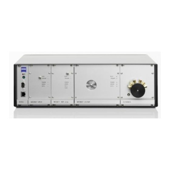
Only use the fuse types specified in the "Specifications" section. Warning Heat build-up! Keep the ventilation slots in the base plate clear! MCS 600 | User Manual... - Page 16 The IP address can also be changed via ethernet once a connection is established. The default address is 192.168.0.100. ECCU Ethernet port (10/100) 64-pin connector for electrical connection of up to four 14 TE spectro- meter cassettes and one lamp cassette (right) MCS 600 | User Manual...
-
Page 17: Specifications
24 V connector 4 x GND (short-circuit proof, limited current) 3.2.4 Specifications Designation Description Power connection 100 – 240 V AC, 50/60 Hz Power consumption < 100 VA (depending on component configuration) Fuses 2 x T2 A/H Protection class IP 20 MCS 600 | User Manual... - Page 18 OUT 0 Warning Maximum load: 24 V DC: 800 mA Maximum load: OUT 0 through 7: 100 mA each Only connect Trigger IN to bounce-free and potential-free contacts. Overload may cause the system to reset! MCS 600 | User Manual...
- Page 19 Fig. 5 Designation of the slots for 14 TE spectrometer cassettes (for 9.5 and 14-inch analog housings) ECCU SLOT 1 SLOT 2 SLOT 3 SLOT 4 LAMPENSLOT ECCU SLOT 2 SLOT 3 SLOT 4 LAMPENSLOT MCS 600 | User Manual...
- Page 20 3. Place the new cassette on the module support and slide it into the housing until you feel it snap into place. 4. Tighten the cassette firmly with the securing screws and reconnect the cables and/or light guides. 5. Plug in the power cable and turn the device on. MCS 600 | User Manual...
- Page 21 4. Insert the new T2 A/H fuse(s), slide the fuse holder(s) back into place and close the drawer. 5. Plug in the device again and turn it on. 3.2.10 Spare parts Fig. 6 Changing fuses Power plug Drawer Fuse Fuse holders Designation Cat. no. 2 fuses, T2 A/H 000000-0499.204 MCS 600 | User Manual...
- Page 22 MCS 600 MCS 600 | User Manual...
-
Page 23: Mcs 601 Uv-Nir Spectrometer Cassette
SMA connector Handle rail (for removing the cassette) LED BUSY LED TRIGGER LED POWER LED ERROR LED SETTLING 64-pin connector for electrically connecting slide-in cassettes Fig. 8 MCS 601 UV-NIR spec- trometer cassette, rear view MCS 600 | User Manual... - Page 24 5. Plug in the power cable and turn the device on. Note Submit defective slide-in cassettes to our Customer Service team for repair. The address can be found on page 2 of this document. MCS 600 | User Manual...
-
Page 25: Mcs 611 Nir 2.2 Spectrometer Cassette
Handle rail (for removing the cassette) LED BUSY LED TRIGGER LED POWER LED ERROR LED SETTLING LED TEMP 64-pin connector for electrically connecting slide-in cassettes Fig. 10 MCS 611 NIR 2.2 spectrometer cassette, rear view MCS 600 | User Manual... - Page 26 5. Plug in the power cable and turn the device on. Note Submit defective slide-in cassettes to our Customer Service team for repair. The address can be found on page 2 of this document. MCS 600 | User Manual...
-
Page 27: Mcs 621 Vis Ii Spectrometer Cassette
SMA connector Handle rail (for removing the cassette) LED BUSY LED TRIGGER LED POWER LED ERROR LED SETTLING 64-pin connector for electrically connecting slide-in cassettes Fig. 12 MCS 621 VIS II spectrometer cassette, rear view MCS 600 | User Manual... - Page 28 5. Plug in the power cable and turn the device on. Note Submit defective slide-in cassettes to our Customer Service team for repair. The address can be found on page 2 of this document. MCS 600 | User Manual...
-
Page 29: Svs 600 Electrical Power Supply Cassette
Fig. 13 SVS 600 electrical power supply cassette, front view Fastening screws Electrical power supply cable connection ON/OFF switch Handle rail Interface for MCS 600 housing Fig. 14 SVS 600 electrical power supply cassette, rear view MCS 600 | User Manual... - Page 30 MCS 600 MCS 600 | User Manual...
-
Page 31: Lamp Cassettes
3.7.1 Intended use ZEISS lamp cassettes are highly stable light sources intended for use in spectros- copy. The cassettes are modular components and may only be used in MCS 600 system housings. The manufacturer must first be consulted before the cassettes may be used for any other purpose. - Page 32 MCS 600 MCS 600 | User Manual...
-
Page 33: Blx 600/Sma Lamp Cassette
MCS 600 3.8 BLX 600/SMA lamp cassette 3.8.1 Overview Fig. 15 BLX 600/SMA lamp cassette Fig. 16 BLX 600/SMA lamp cassette, rear view Fastening screws SMA connector Handle rail Interface for MCS 600 housing MCS 600 | User Manual... - Page 34 These voltages are generated in and accumulate in the electronics. Do not attempt to modify the internal electronics or wiring! 3.8.3 Spare parts for the BLX 600/SMA lamp cassette Designation Cat. no. Flash Bulb L4633-01 000000-0235-825 MCS 600 | User Manual...
- Page 35 10. Reattach the upper and rear grill plates to the lamp cassette housing. 11. Slide the lamp cassette back into the housing and retighten the fastening screws. 12. You can now reconnect the spectrometer system to the power supply and turn it on. MCS 600 | User Manual...
- Page 36 MCS 600 Fig. 17 BLX 600/SMA lamp replacement MCS 600 | User Manual...
-
Page 37: Blx 600/Cz6 Lamp Cassette
MCS 600 3.9 BLX 600/CZ6 lamp cassette 3.9.1 Overview Fig. 18 BLX 600/CZ6 lamp cassette Fig. 19 BLX 600/CZ6 lamp cassette, rear view Fastening screws Zeiss CZ6 connector Handle rail Interface for MCS 600 housing MCS 600 | User Manual... - Page 38 These voltages are generated in and accumulate in the electronics. Do not attempt to modify the internal electronics or wiring! 3.9.3 Spare parts for the BLX 600/CZ6 lamp cassette Designation Cat. no. Flash Bulb L4633-01 000000-235-825 MCS 600 | User Manual...
- Page 39 10. Reattach the upper and rear grill plates to the lamp cassette housing. 11. Slide the lamp cassette back into the housing and retighten the fastening screws. 12. You can now reconnect the spectrometer system to the power supply and turn it on. MCS 600 | User Manual...
- Page 40 MCS 600 Fig. 20 BLX 600/CZ6 lamp replacement MCS 600 | User Manual...
-
Page 41: Blx 606 Lamp Cassette
MCS 600 3.10 BLX 606 lamp cassette 3.10.1 Overview Fig. 21 BLX 606 lamp cassette Fig. 22 BLX 606 lamp cassette, rear view Fastening screws SMA connectors Handle rail Interface for MCS 600 housing MCS 600 | User Manual... - Page 42 These voltages are generated in and accumulate in the electronics. Do not attempt to modify the internal electronics or wiring! 3.10.3 Spare parts for the BLX 606 lamp cassette Designation Cat. no. Flash Bulb L4633-01 000000-1345-781 MCS 600 | User Manual...
- Page 43 10. Reattach the upper and rear grill plates to the lamp cassette housing. 11. Slide the lamp cassette back into the housing and retighten the fastening screws. 12. You can now reconnect the spectrometer system to the power supply and turn it on. MCS 600 | User Manual...
- Page 44 MCS 600 Fig. 23 BLX 606 lamp replacement MCS 600 | User Manual...
-
Page 45: Cld 600 Lamp Cassette
MCS 600 3.11 CLD 600 lamp cassette 3.11.1 Overview Fig. 24 CLD 600 lamp cassette Fig. 25 CLD 600 lamp cassette, rear view Fastening screws SMA connector Handle rail Interface for MCS 600 housing MCS 600 | User Manual... - Page 46 Doing so will result in injury to the eyes. Please observe the relevant regulations when handling UV light sources. 3.11.4 Spare parts for CLD 600 lamp cassette Designation Cat. no. Deuterium lamp for CLD 600 000000-1446-440 MCS 600 | User Manual...
- Page 47 Slide the lamp cassette back into the housing and retighten the fastening screws. 11. Reconnect the device to the power supply and turn it on. Note To achieve accurate measurements, the new deuterium lamp must first be allowed to burn for 14 hours. MCS 600 | User Manual...
- Page 48 MCS 600 Fig. 26 CLD 600 lamp replacement MCS 600 | User Manual...
-
Page 49: Clh 600 Lamp Cassette
MCS 600 3.12 CLH 600 lamp cassette 3.12.1 Overview Fig. 27 CLH 600 lamp cassette Fig. 28 CLH 600 lamp cassette, rear view Fastening screws SMA connector Handle rail ON/OFF shutter Interface for MCS 600 housing MCS 600 | User Manual... - Page 50 (e.g. conjunctivitis). Please observe the relevant regulations when handling light sources of this type. 3.12.4 Spare parts for CLH 600 lamp cassette Designation Cat. no. Halogen lamp 5V/1.8A for CLH 600 000000-1446-069 MCS 600 | User Manual...
- Page 51 You do not need to reattach the cable tie. 9. Reattach the upper grating and tighten the screws. 10. Insert the lamp cassette again and tighten the screws. 11. Reconnect the device to the power supply and turn it on. MCS 600 | User Manual...
- Page 52 MCS 600 Fig. 29 CLH 600 lamp replacement MCS 600 | User Manual...
-
Page 53: Clh 600 F Lamp Cassette
3.13 CLH 600 F lamp cassette 3.13.1 Overview Fig. 30 CLH 600 F lamp cassette Fig. 31 CLH 600 F lamp cassette, rear view Fastening screws SMA connector Handle rail ON/OFF shutter Interface for MCS 600 housing MCS 600 | User Manual... - Page 54 (e.g. conjunctivitis). Please observe the relevant regulations when handling light sources of this type. 3.13.4 Spare parts for CLH 600 F lamp cassette Designation Cat. no. Halogen lamp 5V/1.8A for CLH 600 000000-1446-069 MCS 600 | User Manual...
- Page 55 You do not need to reattach the cable tie. 9. Reattach the upper grating and tighten the screws. 10. Insert the lamp cassette again and tighten the screws. 11. Reconnect the device to the power supply and turn it on. MCS 600 | User Manual...
- Page 56 MCS 600 Fig. 32 CLH 600 F lamp replacement MCS 600 | User Manual...
-
Page 57: Clh 606 A Lamp Cassette
3.14 CLH 606 A lamp cassette 3.14.1 Overview Fig. 33 CLH 606 A lamp cassette Fig. 34 CLH 606 A lamp cassette, rear view Fastening screws SMA connectors Handle rail ON/OFF shutter Interface for MCS 600 housing MCS 600 | User Manual... - Page 58 (e.g. conjunctivitis). Please observe the relevant regulations when handling light sources of this type. 3.14.4 Spare parts for CLH 606 A lamp cassette Designation Cat. no. Halogen lamp 10V/1.8A for CLH 606 000000-1446-136 MCS 600 | User Manual...
- Page 59 7. Then, reconnect the cable (reverse polarity protection). 8. Reattach the upper grating and tighten the screws. 9. Insert the lamp cassette again and tighten the screws. 10. Reconnect the device to the power supply and turn it on. MCS 600 | User Manual...
- Page 60 MCS 600 Fig. 35 CLH 606 A bulb replacement MCS 600 | User Manual...
-
Page 61: Mcs 600 Network Connection
MCS 600 MCS 600 Network Connection 4 MCS 600 Network Connection We recommend using a CAT 6 S/FTP patch cable for establishing network connec- tions with the MCS 600. Note If the device is connected directly to an older ethernet adapter without auto MDI-X, a crossover patch cable must be used. -
Page 62: Manually Configuring The Device Network (No Dhcp Server)
1. Press the Windows button and enter "Network connections". 2. Select "View network connections". 3. Double-click on the network adaptor you want to connect to the MCS 600. Note If you have multiple network adapters, you can identify the correct adapter by disconnecting and reconnecting the network cable several times. -
Page 63: Embedding The Mcs 600 In A Company Network With A Dhcp Server
4.2 Embedding the MCS 600 in a company network with a DHCP server Request a fixed IP address, subnet mask and gateway for the MCS 600 from your administrator. Configure your settings using these values in accordance with one of the methods provided in section 4.3. -
Page 64: Changing The Mcs 600'S Ip Address
3. The IP address, subnet mask and gateway can be changed in a hyperterminal shortly after restarting the device. To do this, the MCS 600 must be connected via the ECCU's D-Sub port (see figure 1 in section 3.2) to the COM port on a computer using a null modem cable. - Page 65 _____ . _____ . _______ Your set IP address IP address: Changed on: Subnet mask: Gateway: _____ . _____ . _______ Your set IP address IP address: Changed on: Subnet mask: Gateway: _____ . _____ . _______ MCS 600 | User Manual...
- Page 66 MCS 600 Network Connection MCS 600 MCS 600 | User Manual...
-
Page 67: Maintenance And Care
To ensure that your system remains perfectly functional and optically configured for a long time, we recommend concluding a service/maintenance contract with ZEISS. For subsequent orders or if service is required, please contact your local ZEISS representative. MCS 600 | User Manual... - Page 68 Maintenance and Care MCS 600 MCS 600 | User Manual...
Need help?
Do you have a question about the MCS 600 and is the answer not in the manual?
Questions and answers