Table of Contents
Advertisement
Advertisement
Table of Contents

Subscribe to Our Youtube Channel
Related Manuals for Zeiss GOM Scan 1


Summary of Contents for Zeiss GOM Scan 1
- Page 1 Precise Industrial 3D Metrology GOM Scan User Manual Hardware GOM Scan 1...
-
Page 2: Legal Notes
Legal Notes No part of this publication may be reproduced in any form or by any means or used to make any derivative work (such as translations, transfor‐ mations or adaptations) without the prior written permission of GOM. GOM reserves the right to revise this publication and to change contents from time to time without obligation on the part of GOM to provide noti‐... -
Page 3: Table Of Contents
Table of Contents Legal Notes............2 How to Handle Calibration Objects..16 Calibration Conditions......16 Important Notes...........5 Prerequisites..........16 Standard Signal Words.......5 Calibrate Sensor with Calibration Safety and Health Hazard Notes....5 Panel CPA............ 16 Product Description....... - Page 4 0000002121_003_EN_01-09-2021 Page 4 (24)
-
Page 5: Important Notes
Important Notes Standard Signal Words In this publication the following standard signal words can be used: DANGER ▶ The label points to an imminent danger. The situation can lead to seri‐ ous bodily harm or death! WARNING ▶ The label points to a dangerous situation. The situation can lead to serious bodily harm or death! CAUTION ▶... - Page 6 Important Notes WARNING Epileptic seizures or loss of awareness caused by certain light patterns or flashing lights A very small portion of the population (approx. 1 person out of 4000) have a condition which may cause them to experience epileptic seizures or have momentary loss of consciousness when viewing certain kinds of flashing lights and patterns or when playing video games.
- Page 7 Important Notes NOTICE ▶ Never connect cables during operation! Never disconnect cables dur‐ ing operation! NOTICE Company-specific firewall settings Company-specific firewall settings of the Ethernet data connections can cause system failures. ▶ Never change the factory-set firewall for the Ethernet cards for the cameras or the controller! NOTICE Temperature variations can cause condensation.
-
Page 8: Product Description
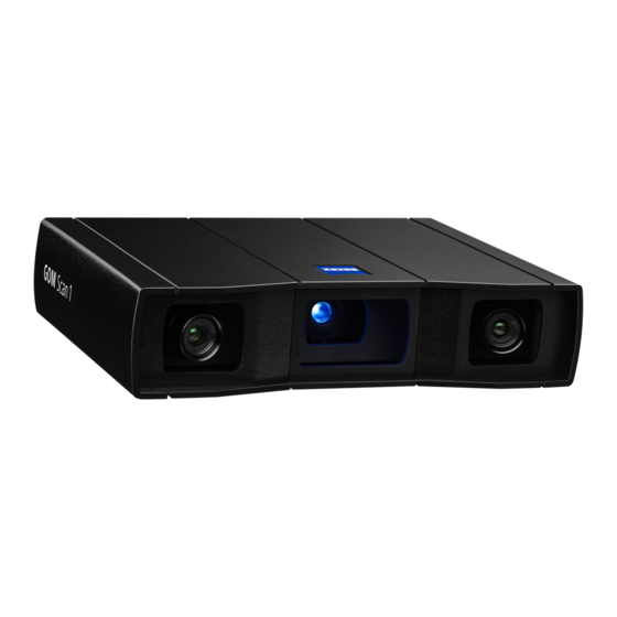
Product Description The GOM Scan 1 sensor (Fig. 1) is designed for full-field 3D scanning. GOM Scan 1 systems are available with a wide range of accessories. Fig. 1: GOM Scan 1 sensor, front view You can use the GOM Scan 1 sensor in manual or semi-automatic opera‐... -
Page 9: System Overview
100 to 240 V, 50 to 60 Hz Power consumption Typically 45 W Power Factor Correction ≥ 85% Max. cable length between sensor and PC, laptop Application software GOM Inspect For more information, visit https://www.gom.com. Tab. 2: GOM Scan 1, general data 0000002121_003_EN_01-09-2021 Page 9 (24) -
Page 10: Information About The Sensor
Information About the Sensor Each configured GOM Scan 1 sensor comprises a defined 3D area in scan direction within which a measuring object can be scanned. Such a 3D area is referred to in the following as a “measuring volume”... -
Page 11: Definition Of Terms
Definition of Terms Fig. 2: Definition of terms 0000002121_003_EN_01-09-2021 Page 11 (24) - Page 12 Definition of Terms Camera position (approxi‐ the center of the measuring mate distance) volume) GOM Scan 1 sensor, sche‐ Camera angle matic representation of the Height H (measuring vol‐ camera lens ume) Camera lens right R (with Width W (measuring vol‐...
-
Page 13: Control Elements And Led Indicators
Control Elements and LED Indicators Fig. 3: Rear LED indicators and external power supply Data connection for the sen‐ LED shows red light. sor, USB Further status information Status display: If the sensor can be found via the web is ready for operation, the interface of the sensor, see LED shows green light. -
Page 14: Web Interface
Web Interface You get to the web interface in the GOM Inspect software via Help Sys‐ ► tem Analysis Sensor Sensor Status. ► ► Info The sensor must be switched on and connected to the measuring com‐ puter. The GOM Inspect software is started. The sensor is not yet initialized Fig. -
Page 15: Calibrate The Sensor
Generally, each measuring volume (MV) has its own calibration object. The table in section 4.1 informs you about which calibration object is required for your measuring volume. For the GOM Scan 1 measuring volumes, different calibration objects are available. The corresponding holding device enables different tilting and tipping of the calibration panel during the calibration procedure. -
Page 16: How To Handle Calibration Objects
Calibrate the Sensor How to Handle Calibration Objects NOTICE Calibration objects are very sensitive. Treat the calibration objects with care. ▶ Do not touch the surface of the calibration object! ▶ After each use, duly accommodate the calibration objects! Info Clean the surface of the calibration object with the enclosed microfiber cloth from the standard tool box. -
Page 17: Handling Instructions For Calibration Panel Cpa
(see section 8.1 How to Handle Calibration Objects). Each calibration object has its own calibration data (file extension .calobj) and its certificate. The calibration data is stored in the GOM Scan 1 sensor. A unique serial number provides for correct matching of calibration object, certificate and calibration data. -
Page 18: Prepare The Calibration
Sensor ► 2. Enter the current measurement temperature in the dialog. 3. Confirm the prompt with OK. The software resets the settings to the recommended calibration set‐ tings. Fig. 7: Calibration of GOM Scan 1 0000002121_003_EN_01-09-2021 Page 18 (24) -
Page 19: Calibration Procedure
Info The GOM Scan 1 sensor is not equipped with laser pointers. The red mark‐ ing in figure Fig. 9 shows the starting position for the calibration. In the first calibration position, the calibration object is in the center of the meas‐... -
Page 20: Calibration Result
Calibrate the Sensor Fig. 9: The image shows the first calibration panel positions (1– 12) in the measuring volume. From calibration step 13, the calibration panel is only tilted and rotated in the center of the measuring volume. The new holding device for the cali‐ bration panel facilitates the positioning due to the different images for the calibration panel. - Page 21 Calibrate the Sensor You also reach the calibration result with Acquisition Sensor Calibra‐ ► ► tion Show Calibration Information. ► Info The application software saves the calibration in the sensor. 0000002121_003_EN_01-09-2021 Page 21 (24)
-
Page 22: Cabling
Cabling Cabling with 19" PC Info Operation of the sensor with a desktop PC is possible with the necessary GOM software. Cabling with Laptop Fig. 10: Cabling GOM Scan 1 with laptop via USB 0000002121_003_EN_01-09-2021 Page 22 (24) -
Page 23: Check And Clean The Dust Filter
Check and Clean the Dust Filter Check the dust filter on the rear side of the sensor in regular intervals. GOM recommends cleaning the filter every three months or more often, depending on the environment. To do so, remove the dirt at the outside of the filter. -
Page 24: Ec Declaration Of Conformity
EC Declaration of Conformity 0000002121_003_EN_01-09-2021 Page 24 (24)
Need help?
Do you have a question about the GOM Scan 1 and is the answer not in the manual?
Questions and answers