Table of Contents
Advertisement
Quick Links
JT550 Series Inverter Manual
Preface
The JT550 is a high-performance and multipurpose industrial product aiming to
integrate synchronous motor drive with asynchronous motor drive, and torque
control, speed control with position control. It is designed with advanced vector
control technology and the latest digital processor dedicated for motor control, thus
enhancing product reliability and adaptability to the environment.
The JT550 adopts customized and industrialized design to realize excellent control
performance through optimized functions and flexible applications.
JT550 uses high power density design. Some power ranges carry built-in DC reactor
and brake unit to save installation space. Through overall EMC design, it can satisfy
the low noise and low electromagnetic interference requirements to cope with
challenging grid, temperature, humidity and dust conditions, thus greatly improving
product reliability.
This operation manual presents installation wiring, parameter setup, fault diagnosis
and trouble shooting, and precautions related to daily maintenance. Read through
this manual carefully before installation to ensure the AC Drive is installed and
operated in a proper manner to give full play to its excellent performance and
powerful functions.
It is the responsibility of the user or machine builder or installation contractor or
electrical designer/engineer to take all necessary precautions to ensure that the
system complies with current standards, and to provide any devices (including safety
components), required to ensure the overall safety of the equipment and personnel.
If there is any doubt with regards to the software version or the manual contents,
please contact us.
- 1 -
Advertisement
Table of Contents

Subscribe to Our Youtube Channel
Related Manuals for Veichi JT550 Series


Summary of Contents for Veichi JT550 Series
- Page 1 JT550 Series Inverter Manual Preface The JT550 is a high-performance and multipurpose industrial product aiming to integrate synchronous motor drive with asynchronous motor drive, and torque control, speed control with position control. It is designed with advanced vector control technology and the latest digital processor dedicated for motor control, thus enhancing product reliability and adaptability to the environment.
-
Page 2: Safety Information And Precautions
Safety Instructions JT550 Series Inverter Manual Safety Information and Precautions Safety definition DANGER It is essential for avoiding a safety hazard. Serious physical injury or even death may occur if related requirements are not followed. WARNING It is necessary for avoiding a risk of damage to the product or other machine. - Page 3 JT550 Series Inverter Manual Safety Instructions Adjusting AC Drive Parameters Disconnect all power sources applied to the AC Drive before terminal wiring, and wait for at least the time designated on the AC Drive after disconnecting the power sources. High voltage presents inside the AC Drive during running. Do not carry out any operation on the AC Drive during running except for keypad setup.
-
Page 4: Table Of Contents
Contents JT550 Series Inverter Manual Contents Preface ................................- 1 - Safety Information and Precautions ....................... - 2 - Contents ................................- 4 - Chapter 1 Product Information ........................- 5 - 1.1 Product Type Identification ......................- 5 - 1.2 Product Nameplate .........................- 5 - 1.3 JT550 Inverter Series ........................ -
Page 5: Chapter 1 Product Information
JT550 Series Inverter Manual Chapter 2 Mechanical Installation Chapter 1 Product Information 1.1 Product Type Identification This is an example of the nameplate of standard JT550 products. JT550 011G / 015 P P: Special type JT550 series AC Drive Mark... -
Page 6: Jt550 Inverter Series
Chapter 2 Mechanical Installation JT550 Series Inverter Manual 1.3 JT550 Inverter Series Product Model Input current (A) Output current (A) Motor (kW) JT550-S2-0R4GB JT550-S2-0R7GB 0.75 JT550-S2-1R5GB JT550-S2-2R2GB Product Model Input current (A) Output current (A) Motor (kW) JT550-T3-0R7G/1R5PB 0.75 JT550-T3-1R5G/2R2PB... -
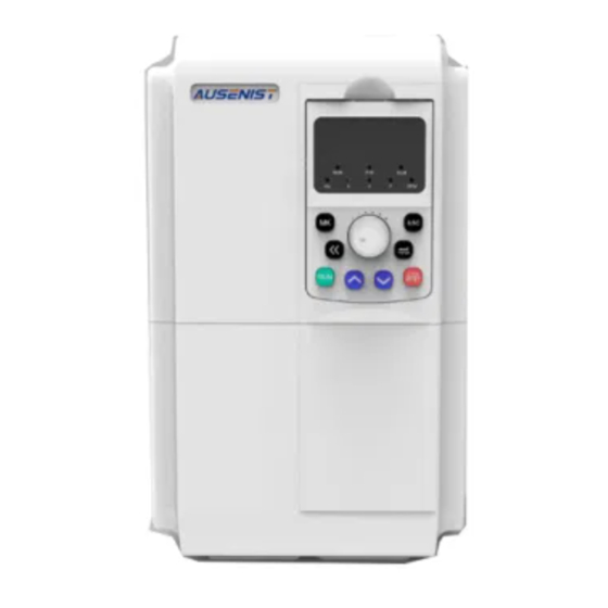
Page 7: Product Description
JT550 Series Inverter Manual Chapter 2 Mechanical Installation 1.4 Product Description Figure 1.3 Components of Plastic Case Model Figure 1.4 Components of the Metallic Case Model - 7 -... - Page 8 Chapter 2 Mechanical Installation JT550 Series Inverter Manual 1.5 Technical Specifications Table 1.2 Technical Specifications of JT550 Item Specification Maximum frequency 320Hz 0.5kHz~16.0kHz Carrier frequency The carrier frequency is automatically adjusted based on the temperature Digital setting:0.01Hz Input frequency resolution Analog setting:maximum frequency×0.025%...
- Page 9 JT550 Series Inverter Manual Chapter 2 Mechanical Installation It can limit the torque automatically and prevent frequent Torque limit and control overcurrent tripping operation.Torque control is applied in vector control mode. High performance high-performance current vector control technology. Load feedback energy compensates for any voltage...
-
Page 10: Product Appearance And Dimensions
Chapter 2 Mechanical Installation JT550 Series Inverter Manual Indoor, free from direct sunlight, dust, corrosive gas, Installation location combustible gas, oil smoke, vapour, drip or salt. Altitude Lower than 1000 m (derated if higher than 1000 m) Ambient temperature -10°C to +40°C (derated if the ambient temperature is Environ- between 40°C and 50°C). - Page 11 JT550 Series Inverter Manual Chapter 2 Mechanical Installation Mounting Diameter of Dimensions Holes Position Mounting Model Holes JT550-S2-0R7GB 71.5 121.5 105.5 114.6 φ4.5 JT550-S2-1R5GB JT550-S2-2R2GB JT550-T3-0R7G/1R5PB 88.4 168.4 φ5.5 JT550-T3-1R5G/2R2PB JT550-T3-2R2G/4R0PB JT550-T3-4R0G/5R5PB 118.4 224.5 163.5 170.5 φ5.5 JT550-T3-5R5G/7R5PB JT550-T3-7R5G/011PB φ7...
- Page 12 Chapter 2 Mechanical Installation JT550 Series Inverter Manual 1.6.2 Cabinet Installation Dimensions Figure 1.7 Installation Diagram L L1 Figure 1.8 Cabinet Installation Dimensions Installation Diameter of Appearance Dimensions (mm) Dimensions Model Mounting Holes JT550-T3-045G/055P φ12 JT550-T3-055G/075P JT550-T3-075G/090P φ10 JT550-T3-090G/110P JT550-T3-110G/132P φ12...
-
Page 13: Keyboard Appearance And Dimensions
JT550 Series Inverter Manual Chapter 2 Mechanical Installation 1.7 Keyboard Appearance and Dimensions Figure 1.9 Appearance and Dimensions of the Keyboard (mm) 1.8 Appearance and Hole Size of the Keyboard Tray 74.2 15.8 托盘开孔尺寸 Figure 1.10 Keyboard Tray Appearance and Hole Size (mm) 键盘托盘尺寸... -
Page 14: Appearance And Dimensions Of The Double Display Keyboard And Tray
Chapter 2 Mechanical Installation JT550 Series Inverter Manual 1.9 Appearance and Dimensions of the Double Display Keyboard and Tray 21.1 14.3 39.1 Figure 1.11 Appearance and Dimensions of the Double Display Keyboard 74.2 15.8 Figure 1.12 Appearance and Dimensions of the Double Display Keyboard and Tray 托盘开孔尺寸... -
Page 15: Chapter 2 Mechanical Installation
JT550 Series Inverter Manual Chapter 2 Mechanical Installation Chapter 2 Mechanical Installation 2.1 Installation Environment 1. Ambient Temperature: The temperature affects the life of product. It is prohibited to run the product out of ambient temperature range (-10 ℃ ℃... - Page 16 Chapter 2 Mechanical Installation JT550 Series Inverter Manual 2.2.3 Multiple Inverters Installed Vertically: In occasions where multiple inverters need installed vertically next to each other, the lower row of inverters’ dissipation of heat will cause a temperature rise of the upper row of inverters, resulting in the overheat/overload errors of the upper row of inverters.
-
Page 17: Dismantling Of The Cover Plate
JT550 Series Inverter Manual Chapter 2 Mechanical Installation 2.3 Dismantling of the Cover Plate 2. Lift the cover to open the inverter. 1. Press inward to disconnect the 2.将盖板往上旋转 1.左右对称向内侧用力 hook from the hook slot. 压挂钩使挂钩松脱 挂钩 Hook Figure 2.2 Remove the Cover Plate (Plastic Case) 2. -
Page 18: Chapter 3 Electrical Installation
Chapter 3 Electrical Installation JT550 Series Inverter Manual Chapter 3 Electrical Installation 3.1 Electrical Installation Three-phase AC power supply Use within the allowable power supply specification of the inverter Moulded Case Circuit Breaker Select a proper breaker to resist large in-rush current... -
Page 19: Description Of Peripheral Electrical Devices
JT550 Series Inverter Manual Chapter 3 Electrical Installation 3.2 Description of Peripheral Electrical Devices Items Function Descriptions Disconnect the power supply when over current occurs on downstream MCCB devices Since the output of the inverter is high-frequency pulse voltage, Residual Current high-frequency leakage occurs sometimes;... -
Page 20: Peripheral Electrical Components Selection Guidance
Chapter 3 Electrical Installation JT550 Series Inverter Manual 3.3 Peripheral Electrical Components Selection Guidance Power Input Power Output MCCB Contactor Control Circuit Converter model Cable Cable Wirings (mm JT550-S2-0R4GB 0.75 0.75 JT550-S2-0R7GB 0.75 0.75 JT550-S2-1R5GB JT550-S2-2R2GB JT550-T3-0R7G/1R5PB 0.75 0.75 0.75 JT550-T3-1R5G/2R2PB 0.75... - Page 21 JT550 Series Inverter Manual Chapter 3 Electrical Installation • Pr: the power of resistor. • D: the braking frequency (percentage of the regenerative process to the whole working process) Common Uncoiling Accidental General Elevator Centrifuge Applications and Coiling Braking Load...
-
Page 22: Selection Of Expansion Card
Chapter 3 Electrical Installation JT550 Series Inverter Manual JT550-T3-500G 20 kW×4 ≥2.5Ω×4 25 kW×4 ≥2.5Ω×4 JT550-T3-560G JT550-T3-630G 28 kW×4 ≥2.5Ω×4 JT550-T3-710G 32 kW×4 ≥2.5Ω×4 • " × 2" indicates that two braking units with each braking resistor are connected in parallel. -
Page 23: Wiring Method
JT550 Series Inverter Manual Chapter 3 Electrical Installation 3.6 Wiring Method A typical wiring method of JT550 Series Inverter is shown below: 2.JT550-T3-045G/055P~710G need to connect with braking unit and braking resistor outside 1.JT550-T3-045G/055P~132G/160P 3.JT550-T3-0R7G/1R5PB~022G/030PB with braking The jumper bar across terminals P1 and (+) must be removed unit inside ,... - Page 24 Chapter 3 Electrical Installation JT550 Series Inverter Manual 3.6.1 Product Terminals and Wiring Single-Phase Inverter’s Terminal Layout of Major Circuit and Size Description: Symbol Name Function Descriptions Single-Phase Power Supply Connect to the single-phase 220V AC power R、T Input Terminals supply +、-...
- Page 25 JT550 Series Inverter Manual Chapter 3 Electrical Installation M4组合螺钉 M4 Combination Screw Figure 3.4 Three -Phase 0.75-2.2kW Inverter’s Terminal Layout of Major Circuit and Size Diagram Rated Recommended Recommended Recommended Recommended Input Input Output Solderless Solderless Ground Cable Model Current...
- Page 26 Chapter 3 Electrical Installation JT550 Series Inverter Manual Figure 3.6 Three -Phase 7.5-11kW Inverter’s Terminal Layout of Major Circuit and Size Diagram Rated Recommended Recommended Recommended Recommended Input Input Output Solderless Model Solderless Ground Cable Current Power Cable Terminal Terminal Models mm²...
- Page 27 JT550 Series Inverter Manual Chapter 3 Electrical Installation 28mm 24mm M8组合螺钉 Figure 3.9 Three -Phase 45-55kW Inverter’s Terminal Layout of Major Circuit and Size Diagram Rated Recommended Recommended Recommended Recommended Input Input Output Solderless Model Solderless Ground Cable Current Power Cable...
- Page 28 Chapter 3 Electrical Installation JT550 Series Inverter Manual Figure 3.11 Three -Phase 110-132kW Inverter’s Terminal Layout of Major Circuit and Size Diagram Rated Recommended Recommended Recommended Recommended Input Input Output Solderless Solderless Model Ground Cable Current Power Cable Terminal Terminal mm²...
- Page 29 JT550 Series Inverter Manual Chapter 3 Electrical Installation 170mm 63mm M16组合螺钉 M16 Combination Screw Figure 3.14 Three -Phase 315-450kW Inverter’s Terminal Layout of Major Circuit and Size Diagram Rated Recommended Recommended Recommended Recommended Input Input Output Solderless Solderless Model Ground Cable...
- Page 30 Chapter 3 Electrical Installation JT550 Series Inverter Manual 50mm 63mm M16 Combination Screw M16组合螺钉 Figure 3.16 Three -Phase 630-710kW Inverter’s Terminal Layout of Major Circuit and Size Diagram Rated Recommended Recommended Recommended Recommended Input Input Output Solderless Solderless Model Ground Cable...
- Page 31 JT550 Series Inverter Manual Chapter 3 Electrical Installation •For the inverter of 45 kW and above, remove the jumper bar across terminals P1 /PR and (+) and install the reactor between the two terminals. e) Output Terminals of Inverter: U, V, W •The specification and installation method of external power cables must comply with the local safety...
- Page 32 Chapter 3 Electrical Installation JT550 Series Inverter Manual 3.6.2 Control Terminals and Wiring Terminal Arrangement of Control Circuit: Output Selection: Voltage Output (Default) Input Selection: Voltage Input (Default) Can switch to current input. 10V AI1 AI2 X5 COM RA RB RC...
- Page 33 JT550 Series Inverter Manual Chapter 3 Electrical Installation Type Terminal Name Function Description Analog input 1、Input voltage range:DC 0V~10V AI1-GND terminal 1 2、Input impedance :22kΩ Analog 1、Input range: DC 0V ~10V /0mA ~20mA, decided input Analog input by the AI2 jumper on the control board.
- Page 34 Chapter 3 Electrical Installation JT550 Series Inverter Manual 3) Wiring of Control Circuit Terminals a) AI Terminals:Weak analog voltage signals are easily interfered, and therefore the shielded cable must be used and the cable length must be less than 20 m, as shown in following figure.
- Page 35 JT550 Series Inverter Manual Chapter 3 Electrical Installation c) SOURCE Wiring +VCC 信号 Control Board External Controller of the Inverter 外部控制器 变频器控制板 Figure 3.21 Wiring in SOURCE Mode This wiring must jump the jumper J12 of PLC to COM, and Connect the + 24V and the COM terminal of the external controller together.
-
Page 36: Chapter 4 Keyboard And Display
Chapter 4 Keyboard and Display JT550 Series Inverter Manual Chapter 4 Keyboard and Display 4.1 Operation and Display Interface Through the operation panel, user may perform such operations such as modifying the function parameters, monitoring the status of inverter, and controlling the operation of inverter (start and stop). Its appearance and... -
Page 37: Keyboard Indicators Description
Table 4.1 Keyboard Functions Table 4.4 Viewing and Modifying Function Codes The operation panel of JT550 series features three-level menu mode: function parameters group (first level of menu), function codes (second level of menu), and function codes modification (third level of menu). -
Page 38: Selecting Menu Mode
4.5 Selecting Menu Mode JT550 series inverter offers three menu modes to select from. User may set the corresponding bit of the menu mode he/she needs as ”1” according to F0.25 and switch using the button “MK”. Follow figure 3-4 to switch the menus after setting the function parameters. -
Page 39: Chapter 5 Basic Operation And Test Run
JT550 Series inverter Manual Chapter 5 Basic Operation and Test Run Chapter 5 Basic Operation and Test Run 5.1 Quick Adjustment Guidance Figure 5.1 Quick Adjustment Procedure - 39 -... -
Page 40: Precautions Before Power-On
Chapter 5 Basic Operation and Test Run JT550 Series inverter Manual 5.2 Precautions Before Power-On Please execute the following steps before power-on. Items Contents Make sure the power voltage is correct Check the power voltage Properly connect the input terminals (R/S/T) of power supply... - Page 41 JT550 Series inverter Manual Chapter 5 Basic Operation and Test Run 5.4.2 Control and Adjustment Flow Chart of V/f and SVC Figure 5.2 Inverter’s Adjustment Sub-Process Flow (V/f Control) - 41 -...
-
Page 42: Initialization Of Parameters
Chapter 5 Basic Operation and Test Run JT550 Series inverter Manual Figure 5.3 Inverter’s Adjustment Sub-Process Flow (Vector Control) 5.5 Initialization of Parameters Restore all of settings to default values. After the initialization, F0.24 is automatically set to 0. F0.24 Restore Default Settings Range:0~501... -
Page 43: Frequency Source Selection
JT550 Series inverter Manual Chapter 5 Basic Operation and Test Run Figure 5.4 Operation Commands Source Selection 5.7 Frequency Source Selection Main Frequency(X) Range:0~13 Default:4 F0.03 Source Selection 0: Digital setting (No saving at power failure) The initial value of the set frequency is the value of F0.08 (Preset frequency). You can change the set frequency by pressing Λ、V on the operation panel (or using the UP/DOWN function of input... - Page 44 Chapter 5 Basic Operation and Test Run JT550 Series inverter Manual When the simple programmable logic controller (PLC) mode is set as the frequency source, the operating frequency of the inverter can be switched over among the 16 frequency references. You can set the holding time and acceleration/deceleration time of the 16 frequency references.
-
Page 45: Stop Modes Selection
5.9.1 Digital Output DO JT550 series inverter comes standard with two digital output terminal Y1, Y2 (Y2 which can be used as high-speed pulse output DO), 2 relay outputs R, E, 2 analog outputs AO1, AO2 (can be selected as the current output). -
Page 46: Chapter 6 Function Parameter List
Chapter 7 Maintenance and Troubleshooting JT550 Series Inverter Manual Chapter 6 Function Parameter List The symbols in the function code table are described as follow: “●” : represents the parameter can be modified while the inverter is operating; “〇” : represents the parameter cannot be modified while the inverter is operating;... - Page 47 JT550 Series Inverter Manual Chapter 7 Maintenance and Troubleshooting Function Default Parameter Name Range of Settings Property Codes Frequency Source ● F0.07 Selection 0.00 to Maximum Frequency (valid when F0.08 Digital Frequency 50.00Hz ● frequency source is set as digital) 0: Forward F0.09...
- Page 48 Chapter 7 Maintenance and Troubleshooting JT550 Series Inverter Manual Function Default Parameter Name Range of Settings Property Codes Digital Frequency F0.20 Property Selection ● Base Frequency of 0: Maximum Frequency (F0.10) F0.21 Acceleration/ 1: Set Frequency 〇 Deceleration time 2: 100 Hz...
- Page 49 JT550 Series Inverter Manual Chapter 7 Maintenance and Troubleshooting Function Default Parameter Name Range of Settings Property Codes 0.001–65.535 Ω (Inverter Power ≤ 55 kW) Harmonic F1.06 Motor Stator Resistance 0.0001–6.5535 Ω (Inverter Power > 55 〇 Parameters 0.001–65.535 Ω (Inverter Power ≤ 55 kW) Harmonic F1.07...
- Page 50 Chapter 7 Maintenance and Troubleshooting JT550 Series Inverter Manual Function Default Parameter Name Range of Settings Property Codes Group F2: Input Terminals F2.00 X1 Function Selection 0: No Function 〇 1: Forward RUN (FWD) F2.01 X2 Function Selection 〇 2: Reverse RUN (REV) F2.02...
- Page 51 JT550 Series Inverter Manual Chapter 7 Maintenance and Troubleshooting Function Default Parameter Name Range of Settings Property Codes F2.10 Terminal X Filter Time 0.000s~1.000s 0.010s ● 0: Two-Wire Mode 1 Terminal Command 1: Two-Wire Mode 2 F2.11 〇 Mode 2: Three-Wire Mode 1...
- Page 52 Chapter 7 Maintenance and Troubleshooting JT550 Series Inverter Manual Function Default Parameter Name Range of Settings Property Codes F2.32 PULSE Filter Time 0.00s~10.00s 0.10s ● F2.33 AI Curve Selection ● Setting for AI Less F2.34 ● Than Minimum Input 0.0s ●...
- Page 53 JT550 Series Inverter Manual Chapter 7 Maintenance and Troubleshooting Function Default Parameter Name Range of Settings Property Codes Group F3:Output Terminals 0:Pulse Output(DO) Y2/DO Terminal Output F3.00 ● Mode 1:Switch Signal Output(Y2) Y1 Output Function 0: No Output F3.01 ●...
- Page 54 Chapter 7 Maintenance and Troubleshooting JT550 Series Inverter Manual Function Default Parameter Name Range of Settings Property Codes DO Output Function 0: Operating Frequency F3.06 ● Selection 1: Set Frequency AO1 Output Function 2: Output Current F3.07 ● Selection 3: Output Torque...
- Page 55 JT550 Series Inverter Manual Chapter 7 Maintenance and Troubleshooting Function Default Parameter Name Range of Settings Property Codes Group F4: Auxiliary Parameters F4.00 JOG Operating Frequency 0.00 Hz to Maximum Frequency 2.00Hz ● F4.01 JOG Acceleration Time 0.0s~6500.0s 20.0s ●...
- Page 56 Chapter 7 Maintenance and Troubleshooting JT550 Series Inverter Manual Function Default Parameter Name Range of Settings Property Codes 0: Disabled F4.27 Terminal JOG Preferred ● 1: Enabled Frequency Detection F4.28 0.00 Hz to Maximum Frequency 50.00Hz ● Value(FDT2) Frequency Detection F4.29...
- Page 57 JT550 Series Inverter Manual Chapter 7 Maintenance and Troubleshooting Function Default Parameter Name Range of Settings Property Codes Current Operating Time F4.53 0.0Min~6500.0Min 0.0Min ● Reached F4.54 ADT1 Channel Selection ● F4.55 ADT2 Channel selection ● ADT1 Output Upper Limit F4.57~10.00 F4.56...
- Page 58 Chapter 7 Maintenance and Troubleshooting JT550 Series Inverter Manual Function Default Parameter Name Range of Settings Property Codes Proportion Gain of F5.13 0~60000 2000 ● Excitation Adjustment Integral Gain of Excitation F5.14 0~60000 1300 ● Adjustment Proportion Gain of Torque F5.15...
- Page 59 JT550 Series Inverter Manual Chapter 7 Maintenance and Troubleshooting Function Default Parameter Name Range of Settings Property Codes F6.18 Current limit gain 0~100 ● Compensation factor of F6.19 speed multiplying current 50%~200% ● limit level 0:Invalid F6.20 Voltage limit selection ●...
- Page 60 Chapter 7 Maintenance and Troubleshooting JT550 Series Inverter Manual Function Default Parameter Name Range of Settings Property Codes Rotational Speed Tracking 100% F7.16 20%~200% ● Current Rotational Speed Tracking F7.17 0~1000 ● Rotational Speed Tracking F7.18 0~1000 ● Rotational Speed Tracking 1.00...
- Page 61 JT550 Series Inverter Manual Chapter 7 Maintenance and Troubleshooting 0000–FFFF Bit00: Set Frequency (Hz) Bit01: Bus Voltage (V) Bit02: Terminal X Input Status Bit03: Digital Output Status Bit04: AI1 Voltage (V) LED Display Parameters at Bit05: AI2 Voltage (V) F8.05 ●...
- Page 62 Chapter 7 Maintenance and Troubleshooting JT550 Series Inverter Manual Function Default Parameter Name Range of Settings Property Codes 0: No Error 1: Reserved 2:Over-current during Acceleration 3:Over-current during Deceleration F9.14 1st fault type 4: Over-current at a Constant Speed 5: Over-voltage during Acceleration...
- Page 63 JT550 Series Inverter Manual Chapter 7 Maintenance and Troubleshooting F9.30 X Status upon 2nd Error - - ◇ Inverter Temperature upon F9.31 - - ◇ 2nd Error Inverter Status upon 2nd F9.32 - - ◇ Error Power-on Time upon 2nd F9.33...
- Page 64 Chapter 7 Maintenance and Troubleshooting JT550 Series Inverter Manual Selection for Fault 00000 F9.49 ● Protection Actions 3 Units (Large Speed Deviation,Err42) Selection for Fault 0: Coast to Stop F9.50 00000 ● Protection Actions 4 1: Stop (Stop Mode) 2: Continue to Run...
- Page 65 JT550 Series Inverter Manual Chapter 7 Maintenance and Troubleshooting Function Default Parameter Name Range of Settings Property Codes Over-speed Detection 20.0% F9.69 0.0%~50.0%(Maximum Frequency) ● Value Over-speed Detection Time 0.0s~60.0s 1.0s F9.70 ● Detection Value of Large 20.0% F9.71 0.0%~50.0%(Maximum Frequency)...
- Page 66 Chapter 7 Maintenance and Troubleshooting JT550 Series Inverter Manual Function Default Parameter Name Range of Settings Property Codes FA.07 Differential Time Td1 0.000s~10.000s 0.000s ● Reverse Cut-off Frequency FA.08 0.00 to Maximum Frequency 0.00Hz ● of PID FA.09 PID Deviation Limit 0.0%~100.0%...
- Page 67 JT550 Series Inverter Manual Chapter 7 Maintenance and Troubleshooting Function Default Parameter Name Range of Settings Property Codes Swing Frequency Fb.01 0.0%~100.0% 0.0% ● Amplitude Fb.02 Jump Frequency Amplitude 0.0%~50.0% 0.0% ● Fb.03 Swing Frequency Cycle 0.1s~3000.0s 10.0s ● Rise Time Coefficient of Fb.04...
- Page 68 Chapter 7 Maintenance and Troubleshooting JT550 Series Inverter Manual Function Default Parameter Name Range of Settings Property Codes FC.02 Command 2 -100.0%~100.0% 0.0% ● FC.03 Command 3 -100.0%~100.0% 0.0% ● FC.04 Command 4 -100.0%~100.0% 0.0% ● FC.05 Command 5 -100.0%~100.0% 0.0%...
- Page 69 JT550 Series Inverter Manual Chapter 7 Maintenance and Troubleshooting Function Default Parameter Name Range of Settings Property Codes Operating Time of Simple FC.24 0.0s(h)~6500.0s(h) 0.0s(h) ● PLC Command 3 Acceleration / Deceleration FC.25 Time of Simple PLC ● Command 3 Operating Time of Simple FC.26...
- Page 70 Chapter 7 Maintenance and Troubleshooting JT550 Series Inverter Manual Function Default Parameter Name Range of Settings Property Codes Acceleration / Deceleration FC.45 Time of Simple PLC ● Command 13 Operating Time of Simple FC.46 0.0s(h)~6500.0s(h) 0.0s(h) ● PLC Command 14 Acceleration / Deceleration FC.47...
- Page 71 JT550 Series Inverter Manual Chapter 7 Maintenance and Troubleshooting Group FE: Quick Menu Parameters Function Default Parameter Name Range of Settings Property Codes FE.00 Quick Menu 0 F0.01 ● FE.01 Quick Menu 1 F0.02 ● FE.02 Quick Menu 2 F0.03 ●...
- Page 72 Chapter 7 Maintenance and Troubleshooting JT550 Series Inverter Manual Function Default Parameter Name Range of Settings Property Codes Corresponding Setting of AI P0.03 30.0% Curve 4 Inflection Point 1 -100.0%~+100.0% ● Input Point AI Curve 4 Inflection P0.04 6.00V P0.02~P0.06 ●...
- Page 73 JT550 Series Inverter Manual Chapter 7 Maintenance and Troubleshooting Function Default Parameter Name Range of Settings Property Codes Factory P1.04 AI2 Measured Voltage 1 0.000V~5.000V ● Corrected Factory P1.05 AI2 Displayed Voltage 1 0.000V~5.000V ● Corrected Factory P1.06 AI2 Measured Voltage 2 5.000V~10.000V...
- Page 74 Chapter 7 Maintenance and Troubleshooting JT550 Series Inverter Manual Function Code Parameter Name Minimum Unit Group H0: Standard Monitoring Parameters H0.00 Operating Frequency (Hz) 0.01Hz H0.01 Set Frequency (Hz) 0.01Hz H0.02 Output Current(A) 0.01A H0.03 Output Voltage(V) H0.04 Output Power(kW)...
- Page 75 JT550 Series Inverter Manual Chapter 7 Maintenance and Troubleshooting Chapter 7 Description of Parameters Group F0: Basic Function F0.00 G/P type Range:1~2 Default:1 1: G type (constant torque load) 2: P type (variable torque load e.g. Fan and pump) F0.01...
- Page 76 Chapter 7 Maintenance and Troubleshooting JT550 Series Inverter Manual If X terminal is used for the multi-reference function, you need to perform related setting in group F2 7: Simple PLC When the simple programmable logic controller (PLC) mode is used as the frequency source, the running frequency of the inverter can be switched over among the 16 frequency references.
- Page 77 JT550 Series Inverter Manual Chapter 7 Maintenance and Troubleshooting Figure7.1 Frequency setting F0.08 Digital frequency Range:0.00Hz~max.freq Default:50.00Hz If the frequency source is digital setting or terminal UP/DOWN, the value of this parameter is the initial frequency of the inverter (digital setting).
- Page 78 Chapter 7 Maintenance and Troubleshooting JT550 Series Inverter Manual If the carrier frequency is low, output current has high harmonics, and the power loss and temperature rise of the motor increase. If the carrier frequency is high, power loss and temperature rise of the motor declines. However, the inverter has an increase in power loss, temperature rise and interference.
- Page 79 JT550 Series Inverter Manual Chapter 7 Maintenance and Troubleshooting Frequency offset of auxiliary Range:0.00Hz~maximum F0.19 frequency source for X and Y Default:0.00Hz frequency operation Digital set frequency attribute F0.20 Range:0~1 Default:0 selection Thousand's digit Hundred's digit Ten's digit Units' digit...
- Page 80 Chapter 7 Maintenance and Troubleshooting JT550 Series Inverter Manual Menu mode switch over by MK. Parameter modification F0.26 Range:0~1 Default:0 property 0: Modifiable 1: Not modifiable It is used to set whether the parameters are modifiable to avoid mal-function. If it is set to 0, all parameters are modifiable.
- Page 81 Group F2:Input Terminal JT550 series inverter have five multi-function input terminals X1 ~ X5 (X5 which can be used as high-speed pulse input), two analog input terminal AI1, AI2 (which can be used as a voltage input AI2, but also as a current input), a keyboard potentiometer.
- Page 82 Chapter 7 Maintenance and Troubleshooting JT550 Series Inverter Manual The terminal is used for fault reset function, the same as the Fault reset (RESET) function of RESET key on the operation panel. The inverter decelerates to stop, but the running parameters are...
- Page 83 JT550 Series Inverter Manual Chapter 7 Maintenance and Troubleshooting After this terminal becomes ON, the inverter directly switches Immediate DC braking over to the DC braking state. Normally closed (NC) input After this terminal becomes ON, the inverter reports Err15 and of external fault stops.
- Page 84 Chapter 7 Maintenance and Troubleshooting JT550 Series Inverter Manual Multi-reference Setting multi- Multi Multi Multi Frequency Corresponding reference -reference -reference -referene setting parameter terminal 4 terminal 3 terminal 2 terminal 1 Reference 0 FC.51 Reference 1 FC.01 Reference 2 FC.02 Reference 3 FC.03...
- Page 85 JT550 Series Inverter Manual Chapter 7 Maintenance and Troubleshooting 1: Two-line mode 2 In this mode, DI1 is RUN enabled terminal, and DI2 determines the running direction. Command Forward Reverse STOP STOP Figure7.4 Setting of two-line mode 2 As shown in the preceding Figure , if K1 is ON, the inverter instructs forward rotation when K2 is OFF, and instructs reverse rotation when K2 is ON.
- Page 86 Chapter 7 Maintenance and Troubleshooting JT550 Series Inverter Manual Two typical setting examples are shown in the following Figure . F2.20 AI curve 2 minimum input Range:0.00V~F2.22 Default:0.20V Corresponding setting of AI F2.21 Range:-100.0%~+100.0% Default:0.0% curve 2 minimum input F2.22 AI curve 2maximum input Range:F2.20~+10.00V...
- Page 87 JT550 Series Inverter Manual Chapter 7 Maintenance and Troubleshooting F2.33 AI curve selection Range:000~555 Default:321 Hundred's digit(AI3curve Unit's digit (AI1 curve Ten's digit (AI2 curve selection) selection) selection) 1:Curve 1:F2.16~F2.19 1:Curve 1:F2.16~F2.19 1:Curve 1:F2.16~F2.19 2:Curve 2:F2.20~F2.23 2:Curve2:F2.20~F2.23 2:Curve2:F2.20~F2.23 3:Curve 3:F2.24~F2.27 3:Curve3:F2.24~F2.27...
- Page 88 Chapter 7 Maintenance and Troubleshooting JT550 Series Inverter Manual F3.01 Range:0~45 Default:1 Y1 function (open collector output terminal) F3.02 Range:0~45 Default:0 Y2 function (open collector output terminal) F3.03 Range:0~45 Default:2 R relay output function selection F3.04 Range:0~45 Default:0 E relay output function selection...
- Page 89 JT550 Series Inverter Manual Chapter 7 Maintenance and Troubleshooting Frequency level detection Refer to the descriptions of F4.28 and F4.29 FDT2 output Frequency 1 reached Refer to the descriptions of F4.30 and F4.31 Frequency 2 reached Refer to the descriptions of F4.32 and F4.33 Current 1 reached Refer to the descriptions of F4.38 and F4.39...
- Page 90 Chapter 7 Maintenance and Troubleshooting JT550 Series Inverter Manual F3.09 Output max.Freq of DO Range:0.01kHz~100.00kHz Default:50.00Hz If the Y2/DO terminal is used for pulse output, this parameter is used to set the maximum frequency of pulse output. F3.10 AO1 offset coefficient Range:-100.0~+100.0...
- Page 91 JT550 Series Inverter Manual Chapter 7 Maintenance and Troubleshooting F3.27 Output terminals valid mode selection Range:0000~1111 Default:0000 It is used to set the logic of output terminals Y1, Y2, relay R, .relay R 0: Positive logic 1: Positive logic Group F4: Auxiliary Functions F4.00...
- Page 92 Chapter 7 Maintenance and Troubleshooting JT550 Series Inverter Manual F4.12 Forward/Reverse rotation dead-zone time Range:0.0s~3000.0s Default:0.0s It is used to set the time when the output is 0 Hz at transition of the inverter forward rotation and reverse rotation, as shown in the following Figure .
- Page 93 JT550 Series Inverter Manual Chapter 7 Maintenance and Troubleshooting F4.19 Frequency detection value (FDT1) Range:0.00Hz~max.freq Default:50.00Hz Frequency detection F4.20 Range:0.0%~100.0% Default:5.0% hysteresis (FDT hysteresis 1) If the running frequency is higher than the value of F4.19, the corresponding Y terminal becomes ON.
- Page 94 Chapter 7 Maintenance and Troubleshooting JT550 Series Inverter Manual Frequency switchover of acceleration F4.25 Range:0.00Hz~max.freq Default:0.00Hz time 1and acceleration time 2 Frequency switchover of deceleration F4.26 Range:0.00Hz~max.freq Default:0.00Hz time 1and deceleration time 2 This function is valid when acceleration/deceleration time switchover is not performed by means of X terminal.
- Page 95 JT550 Series Inverter Manual Chapter 7 Maintenance and Troubleshooting If the output frequency of the inverter is within the positive and negative amplitudes of the any frequency reaching detection value, the corresponding digital output becomes ON. F4.34 Zero current detection level Range:0.0%~300.0%...
- Page 96 Chapter 7 Maintenance and Troubleshooting JT550 Series Inverter Manual If the output current of the inverter is within the positive and negative amplitudes of any current reaching detection value, the corresponding output terminal becomes ON. The JT550 provides two groups of any current reaching detection parameters, including current detection value and detection amplitudes, as shown in the following Figure .
- Page 97 JT550 Series Inverter Manual Chapter 7 Maintenance and Troubleshooting F4.49 Wakeup frequency Range:F4.51~F0.10 Default:0.00Hz F4.50 Wakeup delay time Range:0.0s~6500.0s Default:0.0s F4.51 Dormant frequency Range:0.00Hz~F4.49 Default:0.00Hz F4.52 Dormant delay time Range:0.0~6500.0s Default:0.0s These parameters are used to implement the dormant and wakeup functions in the water supply application.
- Page 98 Chapter 7 Maintenance and Troubleshooting JT550 Series Inverter Manual To improve the system response, increase the proportional gain or reduce the integral time. Remember to increase proportional gain first to ensure that the system does not oscillate, and then reduce integral time to ensure that the system has quick response and small overshoot.
- Page 99 JT550 Series Inverter Manual Chapter 7 Maintenance and Troubleshooting Excitation adjustment F5.13 Range:0~60000 Default:2000 proportional gain Excitation adjustment integral F5.14 Range:0~60000 Default:1300 gain Torque adjustment proportional F5.15 Range:0~60000 Default:2000 gain F5.16 Torque adjustment integral gain Range:0~60000 Default:1300 These function parameters are vector control current loop PI parameters. They are obtained from motor auto-tuning.
- Page 100 Chapter 7 Maintenance and Troubleshooting JT550 Series Inverter Manual F6.09 V/F slip compensation gain Range:0.0%~200.0% Default:0.0% It can compensate the rotational speed slip of the asynchronous motor when the load of the motor increases, stabilizing the motor speed in case of load change. If this parameter is set to 100%, it indicates that the compensation when the motor bears rated load is the rated motor slip.
- Page 101 JT550 Series Inverter Manual Chapter 7 Maintenance and Troubleshooting Range: F6.16 Current limit selection Default:1 0: Disabled 1: Enabled F6.17 Current limit level Range:50% to 200% Default:150% F6.18 Current limit gain Range:0 to 100 Default:20 When output current exceeds the value set in F6.17 during acceleration, constant running or deceleration, current limit is enabled and output frequency starts to drop.
- Page 102 Chapter 7 Maintenance and Troubleshooting JT550 Series Inverter Manual F6.25 Filter Time of V/f Slip Compensation 0~10.0 Used to set the filtering time of V / F slip compensation. F6.26 Auto-Torque Boost Coefficient 0~200 Adjust the value of automatic torque lifting.
- Page 103 JT550 Series Inverter Manual Chapter 7 Maintenance and Troubleshooting F7.05 Startup DC braking current 0%~100% F7.06 Startup DC braking time 0.0s~100.0s 0.0s Startup DC braking is generally used during restart of the inverter after the rotating motor stops.Startup DC braking is valid only for direct start (F7.00 = 0). In this case, the inverter performs DC braking at the set startup DC braking current.
- Page 104 Chapter 7 Maintenance and Troubleshooting JT550 Series Inverter Manual Group F8: Operation Panel and Display F8.01 MK Key function selection Range:0~4 Default:0 MK key refers to multifunctional key. You can set the function of the MK key by using this parameter.
- Page 105 JT550 Series Inverter Manual Chapter 7 Maintenance and Troubleshooting F8.06 Load speed display coefficient Range:0.0001~6.5000 Default:1.0000 This parameter is used to adjust the relationship between the output frequency of the inverter and the load speed. For details, see the description of F8.12.
- Page 106 Chapter 7 Maintenance and Troubleshooting JT550 Series Inverter Manual When motor running current reaches 175% of rated motor current and motor runs at this level for 2 minutes, Err11 (motor overload) is detected. When motor running current reaches 115% of rated motor current and motor runs at this level for 80 minutes, Err11 is detected.
- Page 107 JT550 Series Inverter Manual Chapter 7 Maintenance and Troubleshooting Fault protection action F9.47 Range:0000~2222 Default:0000 selection 1 Ten thousand's Thousand's digit Hundred's digit Ten's digit (Power Unit's digit(Communicat (External (Power output input phase loss, digit :(Motor ion fault, Err16) equipment fault,...
- Page 108 Chapter 7 Maintenance and Troubleshooting JT550 Series Inverter Manual Frequency selection for F9.54 Range:0~4 Default:0 continuing to run upon fault 0: Current running frequency 1: Set frequency 2: Frequency upper limit 3: Frequency lower limit 4: Backup frequency upon abnormality Backup frequency upon F9.55...
- Page 109 JT550 Series Inverter Manual Chapter 7 Maintenance and Troubleshooting Group FA: Process Control PID Function FA.00 PID setting source Range:0~6 Default:0 FA.01 PID digital setting Range:0.0%–100.0% Default:50.0% FA.00 is used to select the channel of target process PID setting. The PID setting is a relative value and ranges from 0.0% to 100.0%.
- Page 110 Chapter 7 Maintenance and Troubleshooting JT550 Series Inverter Manual It decides the regulating intensity of the PID regulator on the deviation change. The longer the differential time is, the larger the regulating intensity is. Differential time is the time within which the feedback value change reaches 100.0%, and then the adjustment amplitude reaches the maximum frequency.
- Page 111 JT550 Series Inverter Manual Chapter 7 Maintenance and Troubleshooting FA.21 PID initial value Range:0.0%~100.0% Default:0.0% FA.22 PID initial value holding time Range:0.00~650.00s Default:0.00s When the inverter starts up, the PID starts closed-loop algorithm only after the PID output is fixed to the PID initial value (FA.21) and lasts the time set in FA.22.
- Page 112 Chapter 7 Maintenance and Troubleshooting JT550 Series Inverter Manual Group FB: Swing Frequency, Fixed Length ,Count and Torque Control The swing frequency function is applied to the textile and chemical fiber fields and the applications where traversing and winding functions are required.
- Page 113 JT550 Series Inverter Manual Chapter 7 Maintenance and Troubleshooting Fb.05 Set length Range:0m~65535m Default:1000m Fb.06 Actual length Range:0m~65535m Default:0m Fb.07 Number of pulses per meter Range:0.1~6553.5 Default:100.0 The preceding parameters are used for fixed length control. The length information is collected by X terminals. Fb.06 (Actual length) is calculated by dividing the number of pulses collected by the X terminal by Fb.07 (Number of pulses each meter).
- Page 114 Chapter 7 Maintenance and Troubleshooting JT550 Series Inverter Manual Forward max.freq in torque Range:0.00Hz to Fb.13 Default:50.00Hz control maximum frequency Reverse max.freq in torque Range:0.00Hz to Fb.14 Default:50.00Hz control maximum frequency Two parameters are used to set the max.freq in forward or reverse rotation in torque control mode.
- Page 115 JT550 Series Inverter Manual Chapter 7 Maintenance and Troubleshooting FC.17 Simple PLC retentive selection Range:00~11 Default:00 PLC retentive upon power failure indicates that the inverter memorizes the PLC running moment and running frequency before power failure and will continue to run from the memorized moment after it is powered on again.
- Page 116 Chapter 7 Maintenance and Troubleshooting JT550 Series Inverter Manual Acceleration/deceleration time of simple FC.27 Range:0~3 Default:0 PLC reference 4 Running time of simple PLC Range: FC.28 Default:0.0s(h) reference 5 0.0s(h)~6553.5s(h) Acceleration/deceleration time of simple FC.29 Range:0~3 Default:0 PLC reference 5 Range: FC.30...
- Page 117 JT550 Series Inverter Manual Chapter 7 Maintenance and Troubleshooting Group FD: User-defined Parameters Reference to Appendix A: MODBUS Communication Protocol Group FE:Quick Menu parameters Quick Menu 0 Default:F0.10 FE.00 Quick Menu 1 Default:F0.02 FE.01 Quick Menu 2 Default:F0.03 FE.02 Quick Menu 3 Default:F0.07...
- Page 118 Chapter 7 Maintenance and Troubleshooting JT550 Series Inverter Manual Corresponding setting of AI P0.07 Range:-100.0%~+100.0% Default:100.0% curve 4 maximum input AI curve 5 minimum input P0.08 Range:-10.00V~P0.10 Default:-10.00V Corresponding setting of AI P0.09 Range:-100.0%~+100.0% Default:-100.0% curve 5 minimum input AI curve 5 inflexion 1 input P0.10...
- Page 119 JT550 Series Inverter Manual Chapter 7 Maintenance and Troubleshooting They have been corrected upon delivery. When you resume the factory values, these parameters will be restored to the factory-corrected values. Generally, you need not perform correction in the applications. Measured voltage indicates the actual output voltage value measured by instruments such as the multimeter.
- Page 120 Chapter 7 Maintenance and Troubleshooting JT550 Series Inverter Manual H0.08 Monitor the IO expansion card It displays state of DI terminals. “ 1” indicates high level signal, and “0” indicates low level signal. Bit4 Bit3 Bit2 Bit1 Bit0 H0.09 DO output state It displays state of DO terminals.
- Page 121 JT550 Series Inverter Manual Chapter 7 Maintenance and Troubleshooting The description of timing running is refer toF4.42~F4.44. H0.29 PLC stage It displays the current PLC stage H0.30 Communication setting value 0.01% It displays the data written by means of the communication address 0x1000.
-
Page 122: Chapter 8 Maintenance And Troubleshooting
Chapter 7 Maintenance and Troubleshooting JT550 Series Inverter Manual Chapter 8 Maintenance and Troubleshooting 8.1 Daily Maintenance and Inspection of JT550 8.1.1 Daily Maintenance Due to the effect of ambient temperature, humidity, dust and vibration, inverter’s components age over time, leading to potential errors or shorter life of the motor dive. Therefore, it is necessary to perform maintenance on the inverter on daily basis. -
Page 123: Warranty
JT550 Series Inverter Manual Chapter 7 Maintenance and Troubleshooting 2) Long period of storage may result in the deterioration of electrolyte capacitance. Therefore, it is necessary to power it on in 2 years and have it stay on for at least 5 hours. Input voltage must slowly rise to the set value using a voltage regulator. - Page 124 Chapter 7 Maintenance and Troubleshooting JT550 Series Inverter Manual 1: Eliminate the peripheral failure; 2: Initiate the identification of 1: Inverter’s output circuit is motor parameters; grounded or short; 3: Adjust the voltage to the normal 2: Control mode is vector and no range;...
- Page 125 JT550 Series Inverter Manual Chapter 7 Maintenance and Troubleshooting 1: Set the parameter correctly; 1: Check if F9.01: motor protection 2: Reduce load and inspect the parameter is appropriately set; Motor Err11 motor and mechanical conditions; 2: Excessive load or motor stalling;...
- Page 126 Chapter 7 Maintenance and Troubleshooting JT550 Series Inverter Manual 1: The encoder model does not 1: Set the encoder type correctly match. based on the actual situation. Encoder 2: The cable connection of the Err20 2: Eliminate external faults. Fault encoder is incorrect.
- Page 127 JT550 Series Inverter Manual Chapter 7 Maintenance and Troubleshooting 8.4 Common Errors and Solutions Error Types Possible Causes Solutions No power grid voltage or voltage is too low; Broken power switch on the drive Inspect input power; board; Check bus voltage;...
- Page 128 Chapter 7 Maintenance and Troubleshooting JT550 Series Inverter Manual Check if there are the loose wires on the contactor; Check if the contactor Err17 Alert Soft-starter does not pull in; malfunctions; Check if 24V power supply can normally power the contactor;...
-
Page 129: Appendix A: Modbus Communication Protocol
Chapter 7 Maintenance and Troubleshooting Appendix A: MODBUS Communication Protocol JT550 series inverters provides RS485 communication port and supports the Modbus-RTU slave communication protocol. Central control may be realized via computers or PLC. Through this communication protocol, it is possible to change the settings of inverter’s operation commands, to modify or read function parameters, and to read inverter’s operation status and error information, etc. - Page 130 Chapter 7 Maintenance and Troubleshooting JT550 Series Inverter Manual The first domain transmitted is device address where hexadecimal is used during the transmission. Network devices continuously monitor the network bus, including pause intervals. When the first domain (address domain) receives messages, each device will decode them to decide if the messages are sent to them.
- Page 131 JT550 Series Inverter Manual Chapter 7 Maintenance and Troubleshooting When Fd.05 is 0 (Non-Standard Modbus Protocol): Byte Count High Bit Byte Count Low Bit F003H High Bit F003H Low Bit CRC CHK Low Bit CRC CHK High Bit When Fd.05 is 1 (Standard Modbus Protocol):...
-
Page 132: Communication Data Address Definition
Chapter 7 Maintenance and Troubleshooting JT550 Series Inverter Manual 1.2.3 CRC Check Methods CRC(Cyclical Redundancy Check) utilizes RTU frame format, and its messages include the error check domain based on CRC method. CRC domain is able to detect the content of messages. CRC domain has two bytes, including 16 bits of binary value. - Page 133 JT550 Series Inverter Manual Chapter 7 Maintenance and Troubleshooting 100CH AI3 Voltage 101CH Input Pulse Frequency, Unit: 1Hz 100DH Count Input 101DH Communication Setting Value 100EH Length Input 101EH Actual Feedback Speed 100FH Load Speed 101FH Main Frequency X Display...
-
Page 134: Description Of Group Fd Communication Parameters
Chapter 7 Maintenance and Troubleshooting JT550 Series Inverter Manual 8) Faults Description of Inverter Faults Faults Information Address 0000: No Error 0015: EEPROM Read-Write Error 0001: Reserved 0016: Inverter Hardware Errors 0002:Over current during Acceleration 0017: Motor Short to Ground... - Page 135 JT550 Series Inverter Manual Chapter 7 Maintenance and Troubleshooting Data Format Factory Value 0: No Check: Data Format <8,N,2> 1: Even Parity Check: Data Format <8,E,1> Fd.01 Range of Settings 2: Odd Parity Check: Data Format <8,O,1> 3: No Check: Data Format <8-N-1>...
- Page 136 Chapter 7 Maintenance and Troubleshooting JT550 Series Inverter Manual - 136 -...
Need help?
Do you have a question about the JT550 Series and is the answer not in the manual?
Questions and answers