
Related Manuals for ILX Lightwave LDX-32420


Summary of Contents for ILX Lightwave LDX-32420
- Page 1 sales@artisantg.com artisantg.com (217) 352-9330 | Visit our website - Click HERE...
- Page 2 User’s Guide High Power Precision Current Source LDX-32420 ILX Lightwave Corporation · 31950 Frontage Road · Bozeman, MT, U.S.A. 59715 · U.S. & Canada: 1-800-459-9459 · International Inquiries: 406-556-2481 · Fax 406-586-9405 · ilx.custhelp.com www.ilxlightwave.com 70041301 January 2010...
-
Page 4: Table Of Contents
Interlocks ............4 Operating the LDX-32420 Precision Current Source ....4 Obtaining Repair Services . - Page 5 Operation Applying Power to Your LDX-32420 ....... . . 11 The Power On Sequence .
- Page 6 USB Driver Installation ......... 27 LDX-32420 Current Source Command Set ......28 Command Syntax .
- Page 7 Laser Forward Voltage Measurement Calibration ....77 Remote Calibration of the LDX-32420 Current Source ....78 Current Source Calibration .
- Page 8 Figure 1.1 LDX-32420 Front View ......5 Figure 1.2 LDX-32420 Rear View ......5 Figure 2.1 Back Panel LD Connector .
- Page 9 L I S T O F F I G U R E S LDX-32420...
- Page 10 Table 2.1 LDX-32420 Default Settings......12 Table 2.2 LDX-32420 Error Indicators ......16 Table 3.1 Substitute Parameter Names .
- Page 11 L I S T O F TA B L E S viii LDX-32420...
-
Page 12: Safety Information And The Manual
• Prolonged storage under adverse conditions • Failure to perform intended measurements or functions If necessary, return the instrument to ILX Lightwave, or authorized local ILX Lightwave distributor, for service or repair to ensure that safety features are maintained (see the contact information later in this section.) -
Page 13: Safety Marking Symbols
Terminal Terminal On: In position of a bistable push control. Off: Out position of a bistable push control. The slash (I) only denotes that mains are on. The circle (O) only denotes that mains are off. LDX-32420... - Page 14 Returning an Instrument If an instrument is to be shipped to ILX Lightwave for repair or service, be sure to: Obtain a Return Authorization number (RA) from ILX Customer Service.
-
Page 15: Comments, Suggestions, And Problems
You must negotiate and settle with the carrier for the amount of damage. Comments, Suggestions, and Problems To ensure that you get the most out of your ILX Lightwave product, we ask that you direct any product operation or service related questions or comments to ILX Lightwave Customer Support. - Page 16 WA R R A N T Y If ILX Lightwave determines that a return to the factory is necessary, you are issued a Return Authorization (RA) number. Please mark this number on the outside of the shipping box. You or your shipping service are responsible for any shipping damage when returning the instrument to ILX Lightwave;...
- Page 17 WA R R A N T Y LDX-32420...
-
Page 18: Introduction And Specifications
Severe transport stress Prolonged storage under adverse conditions Failure to perform intended measurements or functions If necessary, return the LDX-32420 to ILX Lightwave for service and repair to ensure that safety features are maintained. Product Overview The LDX-32420 Precision High Power Laser Diode Current Source provides up to 20A of DC current with a compliance voltage of 4 Volts for testing and controlling high power single emitter laser diodes. -
Page 19: Initial Inspection
Save and Recall functions from the front panel or through the computer interfaces. Initial Inspection When you receive your LDX-32420, verify that the following items were shipped with the instrument: • LDX-32420 Series Instruction Manual •... -
Page 20: Gpib Communication
GPIB Communication Before connecting the LDX-32420 High Power Precision Current Source to a power source, verify that the AC power source matches the setting of the LDX-32420's voltage indicated on the rear panel of the instrument. To avoid electrical shock hazard, connect the instrument to properly earth-grounded, 3-prong receptacles only. -
Page 21: Rack Mounting
Rack Mounting Rack Mounting The LDX-32420 Precision Current Source can be mounted in a standard 19” rack with the optional rack mount kits. The kits contain a rack mount flange and hardware for mounting on either side of the enclosure. All rack mount accessory kits contain mounting instructions. -
Page 22: Figure 1.1 Ldx-32420 Front View
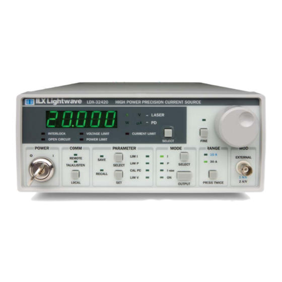
I N T R O D U C T I O N A N D S P E C I F I C A T I O N S C H A P T E R Operating the LDX-32420 Precision Current Source Adjust Section... -
Page 23: Obtaining Repair Services
Obtaining Repair Services Obtaining Repair Services You may have to return your instrument to the ILX Lightwave facility at some time for repair or service whether or not it is under warranty. There is a charge for repairs after the warranty period has expired. Contact an ILX Lightwave service representative for shipping instructions prior to returning the instrument. -
Page 24: Specifications
I N T R O D U C T I O N A N D S P E C I F I C A T I O N S C H A P T E R Specifications Specifications LDX-32420 Drive Current Output Output Current Setpoint Range... - Page 25 I N T R O D U C T I O N A N D S P E C I F I C A T I O N S C H A P T E R Specifications LDX-32420 Bandwidth (3 dB) DC to 100 kHz...
- Page 26 8. From start of output current change to trigger pulse. 9. Measured current through GPIB or USB command; instrument front panel displays setpoint current. 10.The responsivity value is user-defined and is used to calculate the optical power. 01_10 LDX-32420 ...
-
Page 27: Options And Accessories
I N T R O D U C T I O N A N D S P E C I F I C A T I O N S C H A P T E R Specifications Options and Accessories Options and accessories for the LDX-32420 High Power Precision Current Sources include the following: DESCRIPTION MODEL NUMBER... -
Page 28: Applying Power To Your Ldx-32420
C H A P T E R PERATION This chapter introduces you to the operation of the LDX-32420 High Power Precision Current Source. It offers instructions for connecting your laser to the current source and describes powering up the instrument. This chapter also contains step by step procedures that teach you how to operate your current source in Constant Current Mode and Constant Power Mode. -
Page 29: The Power On State
It is also recommended that the connections from the LDX-32420 current source output to the anode and cathode of the laser diode be made using stranded or solid core wire. For best performance in any of the LDX-32420’s operating modes, we recommend the ILX CC-320 or CC-325 interconnect cables which connect directly to the LDX-32420 current source output connector. -
Page 30: Laser Diode Connections
The 9-pin 9W4 connector marked CURRENT SOURCE on the back panel is used to connect your laser diode to the LDX-32420. There are connections provided for laser cathode and anode, photodiode cathode and anode, laser forward voltage and chassis ground. The pinout diagram for this connector is shown in Figure 2.1. -
Page 31: Photodiode Connections
The shield should be connected to earth ground at the LDX-32420 on pin 4 as well as at the source. With the ILX CC-320 and CC-325 interconnect cables, shielded twisted pair 18 AWG conductors are used for the photodiode conductors. -
Page 32: Setting The Pd Bias
Front Panel Operation Setting the PD Bias The LDX-32420 provides an adjustable reverse bias of 0-5 VDC for the photodiode. To set the photodiode bias to 5 V reverse bias, turn the back panel PD BIAS ADJUST fully clockwise. To set the photodiode bias to 0 V reverse bias, turn the back panel PD BIAS ADJUST fully counter-clockwise. -
Page 33: Error Indicators
LED above the push button. Error Indicators The LDX-32420 High Power Precision Current Sources indicate general operational error conditions. Each error condition results in an action as shown in the table below. -
Page 34: Parameter
• I : unit is configured for constant current maximum bandwidth mode • ON: the output is enabled; the LDX-32420 is controlling current to the laser diode • SELECT: switches between constant current and constant power modes of operation; output must be off to change modes •... -
Page 35: Mod
O P E R A T I O N C H A P T E R Front Panel Operation The LDX-32420 allows a modulated voltage signal to be superimposed on the current source output. The input for this signal is a BNC located in the MOD section labeled External. -
Page 36: Fundamentals Of Operation
Fundamentals of Operation Fundamentals of Operation This section describes fundamentals of operation for your LDX-32420 in two operating modes: Constant Current (I) and Constant Power (P). • [ square brackets ]: the equivalent remote commands for the front panel instructions listed. - Page 37 When the SELECT switch is released the measurement mode will be restored. At this point the LDX-32420 is in Constant Current Mode, (I), in the 10A range, and the display is reading in A. Next, we need to adjust the setpoint of the laser current source.
-
Page 38: Conditions That Will Automatically Shut Off The Laser Output
The following conditions will automatically cause the instrument to disable the current source output [LASer:EVEnt?]: • LASER High Power Limit (Laser Event Bit 3) • LASER Interlock 1 or Interlock 2 Activated • LASER Open Circuit or Voltage Limit (Laser Event Bit 6 or Bit 7) 01_10 LDX-32420 ... -
Page 39: Operating A Laser In Constant Power (P) Mode
32420 allows you to operate the laser current source driver in a Constant Optical Power mode. In this mode, the LDX-32420 drives current to the laser to reach a setpoint power value (in W). The control loop feedback parameter is photodiode current which the LDX-32420 converts to optical power via a user-defined photodiode responsivity number. - Page 40 OUTPUT push button once [LASer:OUTput ON]. The accompanying LED labeled ON will illuminate indicating that the laser output is on and current is being driven to the laser. The LDX-32420 current source will drive the laser to the Constant Power setpoint and maintain closed loop control.
- Page 41 O P E R A T I O N C H A P T E R Operating a Laser in Constant Power (P) Mode LDX-32420...
-
Page 42: Remote Operation
(INC) and decrement (DEC) the current set point by a pre-defined step value. The following sections show you the fundamentals of operating your LDX-32420 remotely through the GPIB or USB computer interfaces. Changing Operation from Local to Remote Sending a command over the GPIB or USB bus will automatically put the instrument in remote mode. -
Page 43: Gpib
GPIB The GPIB Address Before you can operate the LDX-32420 instrument remotely, you need to know its GPIB address. The talk and listen addresses on the LDX-32420 current source are identical. Every device on the GPIB bus must have a unique address. -
Page 44: Usb
FLOW CONTOL: NONE USB Driver Installation Insert the companion CD into the PC. This CD is included with the LDX-32420 shipment. The ILX Virtual COM Port Installer should run automatically but if it does not, the executable can be found at [CD-ROM Drive]:\ILX USB Installer.exe. -
Page 45: Ldx-32420 Current Source Command Set
Colons (:) indicate the start of a new command path, while semicolons (;) indicate a separation of commands within a command string. A leading colon on a command may be used to return the LDX-32420 command parser to the command path root (see Figure 3.1). -
Page 46: Table 3.1 Substitute Parameter Names
A query has no space between the mnemonic and the question mark: LAS:LDI? When sending commands through the GPIB bus, the LDX-32420 uses a terminator of <NL><^END> (new line with EOI). For users whose GPIB driver defaults expect a carriage return in the terminator, <CR><NL><^END>, the TERM command may be used for convenience (see TERM command in Chapter 4). -
Page 47: Command Paths
Command Paths Command Paths The LDX-32420 device-dependent commands are structured into a tree format (see Figure 3.1). Each of the legal paths is listed below, followed by its list of path options, each of that is followed by the commands themselves. It is recommended that the first-time user begin learning the commands by using the full path notation. -
Page 48: Ieee488.2 Command Commands
DELAY, or *OPC? Commands. If the time for a response after one of these commands exceed the GPIB time-out period, a bus (time out) error will occur. Usually, after this time out error, the LDX-32420 Series Instrument will generate a query error (E302). This error code is reported via the ERR? Query. -
Page 49: Ldx-32420 Frequently Used Commands
LDX-32420 Frequently Used Commands LDX-32420 Frequently Used Commands The LDX-32420 High Power Precision Current Source’s complete command set contains over 60 commands that allow you to operate the current source for a variety of applications. Within the command set, however, is a smaller subset of commands that will meet most of your needs. -
Page 50: Status Reporting
Querying a Condition Register does not change its contents. Figure 3.3 shows the status reporting scheme of the LDX-32420. Each of the registers that may be accessed by a command or query has the appropriate command or query written above or below the register representation. -
Page 51: Figure 3.2 Ldx-32420 Status Reporting Schematic Diagram
SRQ handling routine in the user's software, that reads a new measurement after the output on state has been reached. This allows the use of the operation complete features of the LDX-32420, without the need for program looping or polling that can tie up the communication bus. Operation Complete on the LDX-32420 is defined as: No operations to the LASER current source hardware are pending. -
Page 52: Output Off Register
Output Off Register The Output Off Enable Register allows you to determine that conditions and events in the LDX-32420 High Power Precision Current Source can cause the current source output to be turned off. This register is configured in a manner similar to the status reporting registers. -
Page 53: Figure 3.3 Ldx-32420 Output Off Register
LASER Output Off Enable Register Turn Output Off LASer:ENABle:OUTOFF <nrf> LASer:ENABle:OUTOFF? Figure 3.3 LDX-32420 Output Off Register 0 - LASER Current Limit 8 - N/A 1 - LASER Voltage Limit 9 - LASER Output Changed to be Out of Tolerance... -
Page 54: Command Timing And Completion
Chapter 3 section titled Operation Complete Definition. All LDX-32420 device-dependent commands are executed in an overlapped manner, except the DELAY command. The operation complete flag is set after the conditions outlined in the Operation Complete Definition have been satisfied. -
Page 55: Error Messages
E-200 to E-299 Execution Control Errors E-300 to E-399 Communication Errors E-500 to E-599 LASER Control Errors Table 3.5 LDX-32420 Series Error Codes Error Code Explanation E-001 Memory allocation failure E-103 <DEFINITE LENGTH ARBITRARY BLOCK PROGRAM DATA> length too long E-104 <NON-DECIMAL NUMERIC PROGRAM DATA>... - Page 56 Laser output must be off to change ranges E-516 Incorrect configuration for calibration sequence to start E-519 Setting a measurement is only valid during the calibration phase for that measurement; user has tried to calibrate a measurement without first entering the required calibration mode. 01_10 LDX-32420 ...
- Page 57 R E M O T E O P E R A T I O N C H A P T E R Error Messages LDX-32420...
-
Page 58: Table 4.1 Ldx-32420 Series Device-Dependent Commands
This chapter is a guide to all of the device-dependent commands for the LDX-32420 High Power Precision Current Source. It is divided into two parts; a command list and a command reference. Table 4.1 lists all of the device dependent commands. -
Page 59: Command Reference
Used to set the LASER high range current source limit LAS:LIM:IHIGH NONE Returns the LASER high range current source limit LAS:LIM:IHIGH? Used to set the constant optical power (from monitor LAS:LIM:MDP photodiode) limit value NONE Used to return the optical power (from monitor LAS:LIM:MDP? photodiode) limit value LDX-32420... - Page 60 Used to add a carriage return to the device terminator TERM NONE Returns the status of the TERM command TERM? NONE Returns the elapsed time since the instrument was last TIME? powered up NONE Returns the elapsed time since the timer was last reset TIMER? 01_10 LDX-32420 ...
-
Page 61: Ldx-32420 Device-Dependent Command Reference
LDX-32420 Device-Dependent Command Reference LDX-32420 Device-Dependent Command Reference This section contains all of device-dependent commands for the LDX-32420 High Power Precision Current Source, listed in alphabetical order. Sub-sections for each path are presented, listing the commands that are legal for that path. See Figure 3.1 for command path tree structure. - Page 62 C O M M A N D R E F E R E N C E C H A P T E R LDX-32420 Device-Dependent Command Reference DELAY <nrf value> RONT ANEL EMOTE The DELAY command causes the execution of commands to be delayed by a user- defined time.
- Page 63 Responsivity:, in A/mW. The range is 0.01 to 100.00. Parameters Notes If the parameter is set to 0, the LDX-32420 will operate in a constant I mode, when Constant P (MDP) mode is selected. The parameter should be set to 0 for I operation modes.
- Page 64 This procedure is outlined in Chapter 6. Examples "Las:CAL:Ldv" - action: the LDX-32420 enters calibration mode for LASER voltage. "LASer:CAL:LDV?" - response: 1, means the LDX-32420 is ready for the user to enter a voltage value via the LASer:LDV command. LASer:CAL:MDI...
- Page 65 C O M M A N D R E F E R E N C E C H A P T E R LDX-32420 Device-Dependent Command Reference LASer:COND? RONT ANEL EMOTE The LASer:COND? query returns the value of the status condition register of the LASER operations.
- Page 66 The default step amount is one step. The step size can be edited via the LAS:STEP command. LDX-32420 default values are 0.001 A, 0.01 W, or 1 µA (if CALMD = 0). If the step parameter is specified, but not the delay parameter, the user may decrement the LASER setpoint by a multiple of the LAS:STEP size, without changing the LAS:STEP size.
- Page 67 C O M M A N D R E F E R E N C E C H A P T E R LDX-32420 Device-Dependent Command Reference LASer:DISplay:LDI RONT ANEL EMOTE LASer:DISplay:LDI? The LASer:DISplay:LDI command sets the laser display to show the constant current measurement value.
- Page 68 C O M M A N D R E F E R E N C E C H A P T E R LDX-32420 Device-Dependent Command Reference LASer:DISplay:MDI RONT ANEL EMOTE LASer:DISplay:MDI? The LASer:DISplay:MDI command sets the laser display to show the monitor photodiode current measurement.
- Page 69 C O M M A N D R E F E R E N C E C H A P T E R LDX-32420 Device-Dependent Command Reference LASer:DISplay:PARAM RONT ANEL EMOTE The LASer:DISplay:PARAM command enables the display to show the parameter values.
- Page 70 C O M M A N D R E F E R E N C E C H A P T E R LDX-32420 Device-Dependent Command Reference LASer:ENABle:COND <flags> RONT ANEL EMOTE LASer:ENABle:COND? The LASer:ENABle:COND command sets the condition status enable register of the LASER operations for summary (in bit 3 of the status byte) and generation of service requests.
- Page 71 C O M M A N D R E F E R E N C E C H A P T E R LDX-32420 Device-Dependent Command Reference LASer:ENABle:EVEnt <flags> RONT ANEL EMOTE LASer:ENABle:EVEnt? The LASer:ENABle:EVEnt command sets the status event enable register of the LASER operations.
- Page 72 C O M M A N D R E F E R E N C E C H A P T E R LDX-32420 Device-Dependent Command Reference LASer:ENABle:OUTOFF <flags> RONT ANEL EMOTE LASer:ENABle:OUTOFF? The LASer:ENABle:OUTOFF command sets the status outoff enable register of the LASER operations (things that will turn the LASER output off).
- Page 73 C O M M A N D R E F E R E N C E C H A P T E R LDX-32420 Device-Dependent Command Reference LASer:EVEnt? RONT ANEL EMOTE The LASer:EVEnt? query returns the value of the status event register of the LASER operations.
- Page 74 The default step amount is one. The step size can be edited via the LAS:STEP command. LDX-32420 default values are 0.001 A, 0.01 W, or 1 µA. If the step parameter is specified, but not the delay, the LASER setpoint is incremented by a multiple of the LAS:STEP size without changing the LAS:STEP size.
- Page 75 C O M M A N D R E F E R E N C E C H A P T E R LDX-32420 Device-Dependent Command Reference LASer:LDV <Volts> RONT ANEL EMOTE LASer:LDV? The LASer:LDV command sets the laser voltage for calibration of the laser voltage measurement.
- Page 76 C O M M A N D R E F E R E N C E C H A P T E R LDX-32420 Device-Dependent Command Reference LASer:LIMit:MDP <Watts> RONT ANEL EMOTE LASer:LIMit:MDP? The LASer:LIMit:MDP command sets the laser monitor photodiode power limit value.
- Page 77 C O M M A N D R E F E R E N C E C H A P T E R LDX-32420 Device-Dependent Command Reference LASer:MDI <Amps> RONT ANEL EMOTE LASer:MDI? The LASer:MDI command sets the value of the optical power setpoint, in µA, if the CALMD (CAL PD) responsivity is 0.
- Page 78 C O M M A N D R E F E R E N C E C H A P T E R LDX-32420 Device-Dependent Command Reference LASer:MODE:IHBW RONT ANEL EMOTE The LASer:MODE:IHBW command selects laser high bandwidth constant current mode.
- Page 79 This range setting effects the Laser Drive Current output current range only. The Laser Drive Current output should be “off” when this command is issued. If the Laser Diode Current output is “on” when this command is issued, the LDX-32420 will generate error E515, and the range will not be changed.
- Page 80 C O M M A N D R E F E R E N C E C H A P T E R LDX-32420 Device-Dependent Command Reference LASer:SET:LDI? RONT ANEL EMOTE The LASer:SET:LDI? query returns the constant current setpoint value that is used for both output ranges and both bandwidths.
- Page 81 Time: represents the time window, in seconds, with a range of 0.001 to 50.000 seconds. Notes The LDX-32420 defaults to a tolerance of 0.010 A for three seconds, unless changed by the LASer:TOLerance command. If the LDX-32420 is operated in P mode, the current tolerance parameter is not used.
- Page 82 C O M M A N D R E F E R E N C E C H A P T E R LDX-32420 Device-Dependent Command Reference RADix {DEC,BIN,HEX,OCT} RONT ANEL EMOTE RADix? The RADix command allows the programmer to select the radix type for status, condition, and event query response data.
- Page 83 "TERM 0" command is sent or the LDX-32420 is powered off. An altered terminator will be in the form <CR><NL><^END>. This termination will be sent with all output until the "TERM 0" command is sent, or the LDX-32420 is powered off. This command has no affect over USB.
-
Page 84: Functions And Features
10A range, a limit setpoint of 8A, a laser current setpoint of 7.5A, and Display Mode I. Once this setup is saved, the LDX-32420 Current Source may be configured for another unique setup. You can recall the original setup for the first experiment any time using the RECALL function. -
Page 85: Saving And Recalling Under Remote Operation
The closer the LASER voltage limit shut off point is to the operating voltage of your laser, the faster the circuit will work in the event of an open circuit. Some experimentation may be necessary for optimum results. LDX-32420... -
Page 86: Using The Ldx-32420 Current Source's Trigger Function
Using the LDX-32420 Current Source’s Trigger Function For applications where you need to synchronously initiate a measurement task from a remote instrument with the LDX-32420 Current Source, the Current Source offers a trigger output signal. The TTL pulse is initiated with any remote change in setpoint of the laser current source. -
Page 87: Using Interlock 2
Linking the LDX-32420 Current Source to a temperature controller* with the ability to signal when its temperature control has gone outside of some tolerance window will allow the LDX-32420 to safely disable the current source output before thermal damage occurs to the laser diode. - Page 88 The modulation port input impedance is 1 k. The transfer function for the low and high current ranges of the LDX-32420 are 1A/V and 2 A/V. Set the LDX-32420 in Constant Current High Bandwidth...
- Page 89 32420 current output is off, an internal short is placed across the output. This short will prevent the modulation signal from reaching the LED. Thus, it is safe to disconnect the test device when the LDX-32420's output is off, regardless of the presence of the modulation signal.
-
Page 90: Calibration And Troubleshooting
LDX-32420 Current Source may be calibrated at its intended use temperature if this is within the specified operating temperature range of 0 to 40°C. Finally, the LDX-32420 Current Source should be allowed to warm up for at least one hour before calibration. LDX-32420... -
Page 91: Recommended Equipment
(I ) feedback circuits. The LDX-32420 Current Source implements a two-point calibration for the Laser current source. Two current levels (approximately 80% and 20% of FS) are applied to a test load, and the resulting current measurements are fed back (by the user) to the Current Source. -
Page 92: Current Source Calibration
(PARAMETER) SET switch is released, the Current Source will calculate the calibration constants and store them to nonvolatile memory. In low bandwidth calibration mode, the LDX-32420 Series Current Source will also perform current limit calibration, indicated by the CURRENT LIMIT LED flashing. -
Page 93: Ipd Current Calibration
After a few seconds the display will show the I setpoint value. After the value on the display is stable (has not changed by more than one digit for several seconds) the LDX-32420 Current Source is ready for the actual I value to be entered. -
Page 94: Laser Forward Voltage Measurement Calibration
4V will be developed across the resistor with 10A of current from the LDX-32420. Connect the voltage sense wires from D-sub on the 32420 and the voltage sense lines from the voltmeter such that they measure voltage across the resistor. -
Page 95: Remote Calibration Of The Ldx-32420 Current Source
However, the *OPC, *WAI command, or *OPC? query should not be issued until after the expected calibration value is entered, or the system will "hang". This happens because the LDX-32420 Current Source will wait indefinitely for an input, yet not allow any input until the calibration is finished. - Page 96 LDX-32420 Current Source is ready to receive it. The Current Source will be ready to receive the new measured value when, after a LAS:CAL:LDI? query is sent, the response from the Current Source is "1".
-
Page 97: Ipd Current Calibration
SETPOINT * 80% of FS LAS:MDI * For this calibration, it is recommended that the current from the LDX-32420 only passes the primary of the current transducer once. With the LASER output off, connect the secondary of the current transducer such that is first passes through the ammeter portion of the DMM and then into the PD anode. -
Page 98: Laser Forward Voltage Measurement Calibration
4V will be developed across this resistor with 10A of current from the LDX-32420. Connect the voltage sense wires from the D-sub on the 32420 and the voltage sense lines from the voltmeter such that they measure voltage across the resistor. -
Page 99: Troubleshooting Guide
C H A P T E R Troubleshooting Guide Troubleshooting Guide This section is a guide to troubleshooting the LDX-32420 Current Sources. Some of the more common symptoms are listed here, and the appropriate troubleshooting actions are given. We recommend that the user start at the beginning of this guide. - Page 100 This indicates a voltage limit error; check laser connections. A high impedance may cause this condition. Open circuit error E503 or voltage The LDX-32420 instruments have an adjustable laser compliance voltage. Check to see if the LASER voltage limit limit error E505 prevents output setting is too low (Chapter 2);...
-
Page 101: Error Messages
E-200 to E-299 Execution Control Errors E-300 to E-399 Communication Errors E-500 to E-599 LASER Control Errors Table 6.3 LDX-32420 Series Error Codes Error Code Explanation E-001 Memory allocation failure E-103 <DEFINITE LENGTH ARBITRARY BLOCK PROGRAM DATA> length too long E-104 <NON-DECIMAL NUMERIC PROGRAM DATA>... - Page 102 Laser output must be off to change ranges E-516 Incorrect configuration for calibration sequence to start E-519 Setting a measurement is only valid during the calibration phase for that measurement; user has tried to calibrate a measurement without first entering the required calibration mode. 01_10 LDX-32420 ...
- Page 103 C A L I B R A T I O N A N D T R O U B L E S H O O T I N G C H A P T E R Error Messages LDX-32420...
Need help?
Do you have a question about the LDX-32420 and is the answer not in the manual?
Questions and answers