
Related Manuals for Huawei iSitePower-M V100R002C00


Summary of Contents for Huawei iSitePower-M V100R002C00
- Page 1 V100R002C00 User Manual (MAP05A1, MAB05B1) iSitePower-M V100R002C00 User Manual (MAP05A1, MAB05B1) Issue Date 2022-07-15 HUAWEI TECHNOLOGIES CO., LTD.
- Page 2 Notice The purchased products, services and features are stipulated by the contract made between Huawei and the customer. All or part of the products, services and features described in this document may not be within the purchase scope or the usage scope. Unless otherwise specified in the contract, all statements, information, and recommendations in this document are provided "AS IS"...
-
Page 3: About This Document
Indicates a potentially hazardous situation which, if not avoided, could result in equipment damage, data loss, performance deterioration, or unanticipated results. NOTICE is used to address practices not related to personal injury. Issue 01 (2022-07-15) Copyright © Huawei Technologies Co., Ltd. - Page 4 Added the label description. ● Added the description of application scenarios. ● Updated the description of battery recharge. ● Updated some specifications. Issue 01 (2021-09-30) This is the first official release. Issue 01 (2022-07-15) Copyright © Huawei Technologies Co., Ltd.
-
Page 5: Table Of Contents
4.3 Genset-Grid Hybrid Scenario............................38 4.4 Solar-Grid Hybrid Scenario..............................39 4.5 Solar-Genset Hybrid Scenario............................41 4.6 Solar-Grid-Genset Hybrid Scenario..........................42 5 System Installation....................... 45 5.1 Installation Preparations..............................45 5.1.1 Checking Before the Installation..........................45 Issue 01 (2022-07-15) Copyright © Huawei Technologies Co., Ltd. - Page 6 8.2.5.3 Installing AC Output Power Cables in a Parallel System................. 93 8.2.5.4 Installing Communications Cables in a Parallel System................... 95 8.3 Genset-Grid Hybrid Scenario............................96 8.3.1 Installing Ground Cables..............................96 8.3.2 Installing the Internal Cable............................97 Issue 01 (2022-07-15) Copyright © Huawei Technologies Co., Ltd.
- Page 7 8.6.6 Installing Genset Control Signal Cables........................146 8.6.7 Installing the Grid Detection Cable of the ATS....................147 8.6.8 Installing Cables in a Parallel System........................148 8.6.8.1 Installing a Ground Cable for the Parallel Box....................148 Issue 01 (2022-07-15) Copyright © Huawei Technologies Co., Ltd.
- Page 8 11.10 Problem Handling................................. 179 11.11 Resetting Password............................... 179 A Technical Specifications....................180 A.1 iSitePower-M system.................................180 A.2 Power Module..................................183 A.3 Battery Module................................... 184 A.4 AC Parallel Box..................................184 B Preparing the Cable and Terminal..................185 Issue 01 (2022-07-15) Copyright © Huawei Technologies Co., Ltd.
- Page 9 V100R002C00 User Manual (MAP05A1, MAB05B1) Contents B.1 Preparing a Cord End Terminal............................. 185 B.2 Preparing an OT Terminal............................... 185 B.3 Preparing a PV Input Power Cable..........................186 B.4 Stripping Length................................. 187 Issue 01 (2022-07-15) Copyright © Huawei Technologies Co., Ltd. viii...
-
Page 10: Safety Precautions
Follow local laws and regulations when installing, operating, or maintaining the equipment. The safety instructions in this document are only supplements to local laws and regulations. Issue 01 (2022-07-15) Copyright © Huawei Technologies Co., Ltd. - Page 11 ● System damage caused by improper operations of a third party or customer, including those in transportation, installation, and adjustment, alteration, or removal of identification marks Issue 01 (2022-07-15) Copyright © Huawei Technologies Co., Ltd.
- Page 12 ● The materials and tools prepared by the customer must comply with the national and local laws, regulations, and relevant standards. Issue 01 (2022-07-15) Copyright © Huawei Technologies Co., Ltd.
-
Page 13: Personnel Requirements
You shall not reverse engineer, decompile, disassemble, adapt, add code to the device software or alter the device software in any other way, research the internal implementation of the device, obtain the device software source code, infringe on Huawei's intellectual property, or disclose any device software performance test results. - Page 14 0°C. Handle cables with caution, especially at a low temperature. – Cables stored at subzero temperatures must be stored at room temperature for at least 24 hours before they are laid out. Issue 01 (2022-07-15) Copyright © Huawei Technologies Co., Ltd.
-
Page 15: Battery Safety
● Batteries are not maintained based on the operation guide, such as failure to check battery terminals regularly. ● Batteries are stolen. ● The warranty period of batteries has expired. Issue 01 (2022-07-15) Copyright © Huawei Technologies Co., Ltd. - Page 16 ● Use tools correctly to avoid hurting people or damaging the equipment. Issue 01 (2022-07-15) Copyright © Huawei Technologies Co., Ltd.
- Page 17 During installation, ensure that the screws are tightened properly using a torque wrench and check them regularly. ● After installing the equipment, remove idle packing materials such as cartons, foam, plastics, and cable ties from the equipment area. Issue 01 (2022-07-15) Copyright © Huawei Technologies Co., Ltd.
- Page 18 ● Overheating may cause batteries to deform and leak corrosive electrolyte or toxic gas. Keep away from the batteries to avoid skin irritation and chemical burns. Issue 01 (2022-07-15) Copyright © Huawei Technologies Co., Ltd.
- Page 19 If the batteries leak or are damaged, contact technical support or a battery recycling company for disposal. ● If the batteries are out of service life, contact a battery recycling company for disposal. Issue 01 (2022-07-15) Copyright © Huawei Technologies Co., Ltd.
-
Page 20: Storage Requirements
The batteries must be stored in a clean, dry, and well-ventilated place and be protected from dust and water vapor corrosion. The batteries must be protected against rain and water. ● Relative humidity: 5% to 80% ● Keep batteries away from direct sunlight. Issue 01 (2022-07-15) Copyright © Huawei Technologies Co., Ltd. -
Page 21: Transportation Requirements
Being dampened by rains, snows, or falling into water ● Falling or mechanical impact ● Being upside-down or tilted NO TE If any of the preceding exceptions occurs, take the emergency measures. Issue 01 (2022-07-15) Copyright © Huawei Technologies Co., Ltd. -
Page 22: Installation Environment Requirements
A salt-affected area refers to the region within 500 meters from the coast or prone to sea breeze. The regions prone to sea breeze vary with weather conditions (such as typhoons and monsoons) or terrains (such as dams and hills). Issue 01 (2022-07-15) Copyright © Huawei Technologies Co., Ltd. -
Page 23: Mechanical Safety
Ensure that the ladder is securely positioned. The recommended angle for a ladder against the floor is 75 degrees, as shown in the following figure. An angle rule can be used to measure the angle. Issue 01 (2022-07-15) Copyright © Huawei Technologies Co., Ltd. -
Page 24: Commissioning
When the equipment is powered on for the first time, ensure that professional personnel set parameters correctly. Incorrect settings may result in inconsistency with local certification and affect the normal operation of the equipment. Issue 01 (2022-07-15) Copyright © Huawei Technologies Co., Ltd. -
Page 25: Maintenance And Replacement
Take out all external tools and parts from the equipment after maintenance is complete. ● If the equipment is not used for a long time, store and recharge batteries according to this document. Issue 01 (2022-07-15) Copyright © Huawei Technologies Co., Ltd. -
Page 26: Product Description
If the insulation fault occurs not only on the PV side, disconnect all relays and shut down the inverter. In inverter mode, PV modules can be used to charge batteries. Issue 01 (2022-07-15) Copyright © Huawei Technologies Co., Ltd. - Page 27 If batteries are available, the system quickly transfers to inverter mode. In bypass mode, both PV modules and the mains can be used to charge batteries. Figure 2-2 Example of the bypass priority mode Issue 01 (2022-07-15) Copyright © Huawei Technologies Co., Ltd.
- Page 28 Table 2-2 Model description Meaning Value Product label iSitePower-M: hybrid power supply series Version MA: product version Module type B: battery module Power level 05: 5kWh Design code B1: module number Issue 01 (2022-07-15) Copyright © Huawei Technologies Co., Ltd.
-
Page 29: Appearance
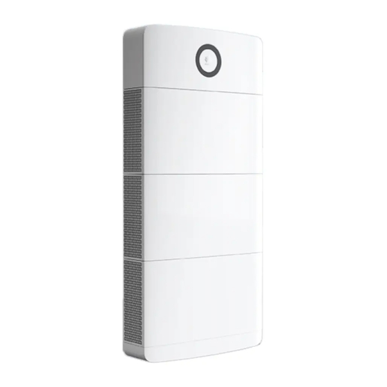
V100R002C00 User Manual (MAP05A1, MAB05B1) 2 Product Description 2.2 Appearance Figure 2-5 Appearance (1) LED indicator (2) Power module (3) Decorative cover (4) Battery modules (5) Base (6) Heat sink Issue 01 (2022-07-15) Copyright © Huawei Technologies Co., Ltd. - Page 30 NOTE A part of the strip light dims when every 10% of battery power is consumed. Blinking green at Indicates that the product is being charging. an interval of 1.25s Issue 01 (2022-07-15) Copyright © Huawei Technologies Co., Ltd.
-
Page 31: System Networking
(A) PV string (B) DC switch (D) Power distribution box (PDB) (E) Load (F) DG (G) Power grid (H) ATS (I) Power distribution cabinet (PDC) The system supports capacity expansion and power expansion. Issue 01 (2022-07-15) Copyright © Huawei Technologies Co., Ltd. - Page 32 ● In parallel connection scenarios, the number of battery modules on the master and slave products must be the same. Table 2-4 Recommended battery configuration Scenario Number of Number of System Capacity Power Modules Battery Modules Single-node 3kVA/5kW system 6kVA/10kW Issue 01 (2022-07-15) Copyright © Huawei Technologies Co., Ltd.
-
Page 33: Label Description
Delayed discharge High voltage still exists after the product is powered off. It takes 5 minutes for the product to discharge to the safe voltage. Issue 01 (2022-07-15) Copyright © Huawei Technologies Co., Ltd. - Page 34 Indicates the MAC address. WiFi login QR code Scan the QR code to connect to the WiFi network of the product and log in to the product to set parameters locally. Issue 01 (2022-07-15) Copyright © Huawei Technologies Co., Ltd.
- Page 35 V100R002C00 User Manual (MAP05A1, MAB05B1) iSitePower-M V100R002C00 User Manual (MAP05A1, MAB05B1) 2 Product Description NO TE The labels are for reference only. Issue 01 (2022-07-15) Copyright © Huawei Technologies Co., Ltd.
-
Page 36: Components
A power module consists of a power unit and a monitoring unit. The power unit is responsible for energy access and conversion. The monitoring unit is responsible for power signal access and monitoring management of PV, grid power, genset power, and batteries. Figure 3-1 Power module Issue 01 (2022-07-15) Copyright © Huawei Technologies Co., Ltd. - Page 37 DIP Switch Figure 3-3 DIP switch Table 3-1 DIP switch description Parallel Pin 1 Pin 2 (A) Pin 3 (B) Pin 4 (C) Remarks Power (M/S) Module Address Master address Slave address Issue 01 (2022-07-15) Copyright © Huawei Technologies Co., Ltd.
- Page 38 DIN1- connect to an ATS. In the grid + genset DIN2+ Dry contact input scenario, the DIN dry DIN 2 contacts are used to DIN2- detect grid signals. Issue 01 (2022-07-15) Copyright © Huawei Technologies Co., Ltd.
- Page 39 10M/100M FE1: BIN protocol/ Parallel control autonegotiation HTTPS protocol communications port FE2: TCP-Modbus protocol NOTE The preceding ports are protected by security mechanisms. Issue 01 (2022-07-15) Copyright © Huawei Technologies Co., Ltd.
- Page 40 CAN bus high level CANL CAN bus low level Table 3-6 Pin definitions for the FE port Signal Description Transmit data over FE. Receive data over FE. 4, 5, 7, 8 Null Issue 01 (2022-07-15) Copyright © Huawei Technologies Co., Ltd.
-
Page 41: Battery Module
The standard capacity is 5 kWh. Figure 3-5 Appearance Figure 3-6 Ports on the battery module (1) Alignment boss (2) COM port (3) Terminals for battery module cascading (4) Heat sink (5) Ground points Issue 01 (2022-07-15) Copyright © Huawei Technologies Co., Ltd. -
Page 42: Optional) Ac Parallel Box Acdb220-90-1B
3.3 (Optional) AC Parallel Box ACDB220-90-1B The AC parallel box is used for paralleling of power modules to increase the system power. A maximum of three power modules can be connected in parallel. Figure 3-7 ACDB220-90-1B Issue 01 (2022-07-15) Copyright © Huawei Technologies Co., Ltd. - Page 43 3 Components Figure 3-8 ACDB220-90-1B interior (1) Ground point on the door (2) Ground bar (3) Cable bags (4) AC input circuit breaker (5) N wiring terminal (6) AC output circuit breaker Issue 01 (2022-07-15) Copyright © Huawei Technologies Co., Ltd.
-
Page 44: Application Scenarios
4.5 Solar-Genset Hybrid Scenario 4.6 Solar-Grid-Genset Hybrid Scenario 4.1 Solar-Only Scenario NO TICE Do not connect optimizers to the system in the solar-only scenario. Otherwise, the system may fail to start. Issue 01 (2022-07-15) Copyright © Huawei Technologies Co., Ltd. - Page 45 If the solar power is less than the load power, solar power and battery power are supplied to loads at the same time. If there is no solar power, batteries power loads. Issue 01 (2022-07-15) Copyright © Huawei Technologies Co., Ltd.
-
Page 46: Grid Scenario
> battery. If grid power is available, grid power is supplied to loads and charges batteries if batteries are not fully charged. If grid power is unavailable, batteries supply power to loads. Issue 01 (2022-07-15) Copyright © Huawei Technologies Co., Ltd. -
Page 47: Genset-Grid Hybrid Scenario
The power source preference sequence is grid > battery > generator set (genset). If grid power is available, grid power is supplied to loads and charges batteries if batteries are not fully charged. Issue 01 (2022-07-15) Copyright © Huawei Technologies Co., Ltd. -
Page 48: Solar-Grid Hybrid Scenario
(DOD) reaches the specified value, the genset is started. When the batteries are fully charged or grid power is available, the genset is shut down. 4.4 Solar-Grid Hybrid Scenario Figure 4-7 Solar-grid hybrid scenario network diagram (one product) Issue 01 (2022-07-15) Copyright © Huawei Technologies Co., Ltd. - Page 49 When solar power is unavailable but grid power is available, grid power is supplied to loads and charges batteries. When solar power and grid power are unavailable, batteries supply power to loads. Issue 01 (2022-07-15) Copyright © Huawei Technologies Co., Ltd.
-
Page 50: Solar-Genset Hybrid Scenario
Figure 4-10 Solar-genset hybrid scenario network diagram (multiple products connected in parallel) In the solar-genset hybrid scenario, the power system works circularly as follows. The power source preference sequence is solar power > battery > genset. Issue 01 (2022-07-15) Copyright © Huawei Technologies Co., Ltd. -
Page 51: Solar-Grid-Genset Hybrid Scenario
If solar power is unavailable, batteries supply power to loads. When the battery DOD reaches the specified value, the genset is started. 4.6 Solar-Grid-Genset Hybrid Scenario Figure 4-11 Solar-grid-genset hybrid scenario network diagram (one product) Issue 01 (2022-07-15) Copyright © Huawei Technologies Co., Ltd. - Page 52 If grid power is available or the batteries are fully charged, the genset is shut down. (A) PV string (B) DC switch (C) AC Parallel Box (D) Power distribution (E) Load (F) DG box (PDB) Issue 01 (2022-07-15) Copyright © Huawei Technologies Co., Ltd.
- Page 53 V100R002C00 User Manual (MAP05A1, MAB05B1) iSitePower-M V100R002C00 User Manual (MAP05A1, MAB05B1) 4 Application Scenarios (G) Power grid (H) ATS (I) Power distribution cabinet (PDC) Issue 01 (2022-07-15) Copyright © Huawei Technologies Co., Ltd.
-
Page 54: System Installation
If any item is missing or damaged, contact your dealer. NO TE For details about the number of deliverables, see the Packing List in the packing case. Issue 01 (2022-07-15) Copyright © Huawei Technologies Co., Ltd. -
Page 55: Tools And Instruments
Diagonal pliers Wire stripper Flat-head insulated torque screwdriver Phillips insulated Rubber mallet Utility knife torque screwdriver Crimping tool, Cord end terminal Cable cutter model: PV-CZM- crimping tool CZM41100 (preferred)/ CZM22100 Issue 01 (2022-07-15) Copyright © Huawei Technologies Co., Ltd. - Page 56 Vacuum cleaner (model: PV-MS- HZ open-end wrench) Multimeter (DC Marker Steel measuring voltage tape measurement range ≥ 600 V Level Hydraulic pliers Heat shrink tubing Heat gun Protective gloves Goggles Anti-dust mask Issue 01 (2022-07-15) Copyright © Huawei Technologies Co., Ltd.
-
Page 57: Determining The Installation Position
● The bearing capacity of the ground must be greater than or equal to 500 kg/m Installation Dimensions Reserve sufficient clearance around the product for installation and heat dissipation. Issue 01 (2022-07-15) Copyright © Huawei Technologies Co., Ltd. -
Page 58: Installing A Mounting Bracket
5.2 Installing a Mounting Bracket 5.2.1 Ground Mounting WARNING The base must be secured to the ground using bolts. Otherwise, the device may tip over, causing personal injury or device damage. Issue 01 (2022-07-15) Copyright © Huawei Technologies Co., Ltd. - Page 59 Figure 5-3 Cutting the marking-off template Step 2 Mark mounting holes for the base. Figure 5-4 Marking mounting holes for the base Step 3 Mark the mounting holes for battery modules. Issue 01 (2022-07-15) Copyright © Huawei Technologies Co., Ltd.
- Page 60 If other types of walls and grounds are used, ensure that the load bearing capacity requirements (the weight of one battery module is 50 kg) are met and appropriate bolts are selected. Issue 01 (2022-07-15) Copyright © Huawei Technologies Co., Ltd.
-
Page 61: Wall Mounting
● Loosen the nut, spring washer, and flat washer of the expansion bolt at the bottom. ----End 5.2.2 Wall Mounting Procedure Step 1 Mark the mounting holes for the wall-mounting bracket and battery modules. Issue 01 (2022-07-15) Copyright © Huawei Technologies Co., Ltd. - Page 62 ● Use the M6x60 expansion bolts delivered with the product to secure the modules. If the length or quantity of the expansion bolts cannot meet the installation requirements, prepare M6 stainless steel expansion bolts by yourself. Figure 5-9 Installing expansion bolts Issue 01 (2022-07-15) Copyright © Huawei Technologies Co., Ltd.
-
Page 63: Installing Modules
Step 4 Install a wall-mounting bracket cover. Figure 5-11 Installing the cover ----End 5.3 Installing Modules NO TICE ● Two persons are required to move a module. ● Battery modules must be secured to the wall. Issue 01 (2022-07-15) Copyright © Huawei Technologies Co., Ltd. - Page 64 Step 3 Install the remaining battery modules and power module from bottom to top. Each time a module is installed, tighten the screws on the left and right, and then secure it against the wall. Issue 01 (2022-07-15) Copyright © Huawei Technologies Co., Ltd.
-
Page 65: Optional) Installing Battery Modules For Capacity Expansion
5.2 Installing a Mounting Bracket 5.3 Installing Modules. Step 1 Remove the L-shaped plates from the top cover, rotate them by 180 degrees, and install them back on the top cover. Issue 01 (2022-07-15) Copyright © Huawei Technologies Co., Ltd. -
Page 66: Optional) Installing An Ac Parallel Box
Figure 5-17 Installing the top cover ----End 5.5 (Optional) Installing an AC Parallel Box Prerequisites In a parallel system, an AC parallel box must be configured. Step 1 Mark mounting holes. Issue 01 (2022-07-15) Copyright © Huawei Technologies Co., Ltd. - Page 67 V100R002C00 User Manual (MAP05A1, MAB05B1) 5 System Installation Figure 5-18 Marking mounting holes Step 2 Install expansion bolts. Figure 5-19 Installing expansion bolts Step 3 Install the AC parallel box on the wall. Issue 01 (2022-07-15) Copyright © Huawei Technologies Co., Ltd.
- Page 68 V100R002C00 User Manual (MAP05A1, MAB05B1) iSitePower-M V100R002C00 User Manual (MAP05A1, MAB05B1) 5 System Installation Figure 5-20 Installing the AC parallel box ----End Issue 01 (2022-07-15) Copyright © Huawei Technologies Co., Ltd.
-
Page 69: Setting The Dip Switch
● The default address is 0 (Pin 1 to Pin 4: OFF). Step 1 Open the power module maintenance compartment. Figure 6-1 Open maintenance compartment Step 2 Set the DIP switch address. Issue 01 (2022-07-15) Copyright © Huawei Technologies Co., Ltd. - Page 70 V100R002C00 User Manual (MAP05A1, MAB05B1) iSitePower-M V100R002C00 User Manual (MAP05A1, MAB05B1) 6 Setting the DIP Switch Figure 6-2 Set the DIP switch address ----End Issue 01 (2022-07-15) Copyright © Huawei Technologies Co., Ltd.
-
Page 71: Preparing Cables
Outdoor shielded twisted pair cable Ground cable Outdoor single-core copper cable (standard scenario) NO TICE In capacity expansion scenarios, you need to purchase power cables and signal cables for bottom cascading from Huawei. Issue 01 (2022-07-15) Copyright © Huawei Technologies Co., Ltd. -
Page 72: Cables Prepared By The Customer
(same as the cross- (customer side) sectional area of the AC input power cable) Ground Ground point Outdoor single-core Main ground cable: 6 mm point on the copper cable module for capacity expansion Issue 01 (2022-07-15) Copyright © Huawei Technologies Co., Ltd. -
Page 73: Grid Scenario
4–6 mm (customer side) ● Cable outer diameter: 13.7–16.9 mm AC input Outdoor three-core copper ● Conductor cross- cable (L/N/PE) (customer sectional area: 4–6 mm side) ● Cable outer diameter: 13.7–16.9 mm Issue 01 (2022-07-15) Copyright © Huawei Technologies Co., Ltd. - Page 74 ● Cable outer diameter: 16–26 mm AC parallel Ground bar Outdoor single-core ● Conductor cross- copper cable (customer sectional area: 25 mm side) ● Cable outer diameter: 8– 11 mm Issue 01 (2022-07-15) Copyright © Huawei Technologies Co., Ltd.
-
Page 75: Genset-Grid Hybrid Scenario
AC input power cable) COM and Genset Outdoor shielded twisted ● Conductor cross- dry contact control pair cable (8 cores) sectional area: 0.2–1 ports signal/ATS ● Cable outer diameter: 6.3–7.5 mm Issue 01 (2022-07-15) Copyright © Huawei Technologies Co., Ltd. -
Page 76: Solar-Grid Hybrid Scenario
4–6 mm (customer side) ● Cable outer diameter: 13.7–16.9 mm AC input Outdoor three-core copper ● Conductor cross- cable (L/N/PE) sectional area: 4–6 mm (customer side) ● Cable outer diameter: 13.7–16.9 mm Issue 01 (2022-07-15) Copyright © Huawei Technologies Co., Ltd. - Page 77 4–6 mm ● Cable outer diameter: 13.7–16.9 mm AC parallel Outdoor three-core copper ● Conductor cross- cable (L/N/PE) (customer sectional area: 25 mm side) ● Cable outer diameter: 16–26 mm Issue 01 (2022-07-15) Copyright © Huawei Technologies Co., Ltd.
-
Page 78: Solar-Genset Hybrid Scenario
(same as the cross- (customer side) sectional area of the AC input power cable) Ground Ground point Outdoor single-core Main ground cable: 6 mm point on the copper cable module for capacity expansion Issue 01 (2022-07-15) Copyright © Huawei Technologies Co., Ltd. - Page 79 ● Cable outer diameter: 16–26 mm AC parallel Ground bar Outdoor single-core ● Conductor cross- copper cable sectional area: 25 mm (customer side) ● Cable outer diameter: 8– 11 mm Issue 01 (2022-07-15) Copyright © Huawei Technologies Co., Ltd.
-
Page 80: Solar-Grid-Genset Hybrid Scenario
Other End Type Recommended Specifications PV input DC switch Common outdoor PV ● Conductor cross- ports cable in the industry (customer sectional area: 4–6 mm side) ● Cable outer diameter: 5.5–9 mm Issue 01 (2022-07-15) Copyright © Huawei Technologies Co., Ltd. - Page 81 ● Cable outer diameter: 16–26 mm AC parallel Ground bar Outdoor single-core ● Conductor cross- copper cable sectional area: 25 mm (customer side) ● Cable outer diameter: 8– 11 mm Issue 01 (2022-07-15) Copyright © Huawei Technologies Co., Ltd.
-
Page 82: Electrical Connection
8.1 Solar-Only Scenario 8.2 Grid Scenario 8.3 Genset-Grid Hybrid Scenario 8.4 Solar-Grid Hybrid Scenario 8.5 Solar-Genset Hybrid Scenario 8.6 Solar-Grid-Genset Hybrid Scenario 8.7 (Optional) Installing Cables in Capacity Expansion Scenario Issue 01 (2022-07-15) Copyright © Huawei Technologies Co., Ltd. -
Page 83: Solar-Only Scenario
8.1.1 Installing Ground Cables Precautions D ANGER Ensure that the ground cable is securely connected. Otherwise, electric shocks may occur. Procedure Step 1 Install ground cables. Figure 8-1 Installing ground cables ----End Issue 01 (2022-07-15) Copyright © Huawei Technologies Co., Ltd. -
Page 84: Installing The Internal Cable
When a communications terminal is connected to a single network cable, a waterproof rubber plug must be installed. Procedure Step 1 Install ground cables. Figure 8-2 Installing ground cables Step 2 Installing battery module power cables. Issue 01 (2022-07-15) Copyright © Huawei Technologies Co., Ltd. - Page 85 Lock the communications terminal waterproof gland. Reinstall the waterproof rubber plug. Tighten the locking cap and secure the signal cables using cable clips. Step 4 Install communications cables for other battery modules in sequence. Issue 01 (2022-07-15) Copyright © Huawei Technologies Co., Ltd.
-
Page 86: Installing Pv Input Power Cables
Step 1 Use a removal wrench to remove the waterproof gland from the PV input terminal on the power module. NO TE Take out the removal wrench from the decorative cover delivered with the product. Step 2 Install the PV input power cables. Issue 01 (2022-07-15) Copyright © Huawei Technologies Co., Ltd. -
Page 87: Install The Ac Output Power Cable
In a single-node system, connect the other end of the AC output power cable to a PDB. In a parallel system, connect the other end of the AC output power cable to the AC parallel box. Procedure Step 1 Connect AC power cables to the terminal connectors. Issue 01 (2022-07-15) Copyright © Huawei Technologies Co., Ltd. -
Page 88: Installing Cables In A Parallel System
Figure 8-7 Installing an AC output power cable ----End 8.1.5 Installing Cables in a Parallel System 8.1.5.1 Installing a Ground Cable for the Parallel Box Procedure Step 1 Install a ground cable. Issue 01 (2022-07-15) Copyright © Huawei Technologies Co., Ltd. -
Page 89: Installing Ac Output Power Cables In A Parallel System
● The three cables from the AC output circuit breaker to the power modules must be of the same length. Procedure Step 1 Install AC output power cables of the parallel box. Issue 01 (2022-07-15) Copyright © Huawei Technologies Co., Ltd. - Page 90 V100R002C00 User Manual (MAP05A1, MAB05B1) iSitePower-M V100R002C00 User Manual (MAP05A1, MAB05B1) 8 Electrical Connection Figure 8-9 Install AC output power cables of the parallel box Issue 01 (2022-07-15) Copyright © Huawei Technologies Co., Ltd.
-
Page 91: Installing Communications Cables In A Parallel System
Step 1 Install communications cables between parallel power modules. Figure 8-10 Installing communications cables (1) Build-out resistor Step 2 Connect the FE ports of the master and slave devices using a network cable. Issue 01 (2022-07-15) Copyright © Huawei Technologies Co., Ltd. -
Page 92: Grid Scenario
Figure 8-11 Installing monitoring communications cables ----End 8.2 Grid Scenario 8.2.1 Installing Ground Cables Precautions D ANGER Ensure that the ground cable is securely connected. Otherwise, electric shocks may occur. Procedure Step 1 Install ground cables. Issue 01 (2022-07-15) Copyright © Huawei Technologies Co., Ltd. -
Page 93: Installing The Internal Cable
NO TICE When a communications terminal is connected to a single network cable, a waterproof rubber plug must be installed. Procedure Step 1 Install ground cables. Issue 01 (2022-07-15) Copyright © Huawei Technologies Co., Ltd. - Page 94 Install battery module power cables. Use a removal wrench to remove the waterproof glands from the battery terminals on the power module. Install power cables between the battery modules and power module. Issue 01 (2022-07-15) Copyright © Huawei Technologies Co., Ltd.
- Page 95 Lock the communications terminal waterproof gland. Reinstall the waterproof rubber plug. Tighten the locking cap and secure the signal cables using cable clips. Step 4 Install communications cables for other battery modules in sequence. Issue 01 (2022-07-15) Copyright © Huawei Technologies Co., Ltd.
-
Page 96: Install The Ac Output Power Cable
A leakage protection device must be configured for the AC output of the system. The leakage current must be 30 mA. You need to configure and install the device by yourself. Issue 01 (2022-07-15) Copyright © Huawei Technologies Co., Ltd. - Page 97 Step 1 Connect AC power cables to the terminal connectors. Figure 8-16 Connecting cables to terminals Step 2 Install the AC output power cable and secure the cable using cable clips. Figure 8-17 Installing an AC output power cable ----End Issue 01 (2022-07-15) Copyright © Huawei Technologies Co., Ltd.
-
Page 98: Install The Ac Input Power Cable
Step 1 Connect AC power cables to the terminal connectors. Figure 8-18 Connecting cables to terminals Step 2 Install the AC input power cable and secure the cable using cable clips. Issue 01 (2022-07-15) Copyright © Huawei Technologies Co., Ltd. -
Page 99: Installing Cables In A Parallel System
Figure 8-19 Installing an AC input power cable ----End 8.2.5 Installing Cables in a Parallel System 8.2.5.1 Installing a Ground Cable for the Parallel Box Procedure Step 1 Install a ground cable. Issue 01 (2022-07-15) Copyright © Huawei Technologies Co., Ltd. -
Page 100: Installing Ac Input Power Cables In A Parallel System
● The three cables from the AC input circuit breaker to the power modules must be of the same length. Procedure Step 1 Install AC input power cables of the parallel box. Issue 01 (2022-07-15) Copyright © Huawei Technologies Co., Ltd. - Page 101 V100R002C00 User Manual (MAP05A1, MAB05B1) iSitePower-M V100R002C00 User Manual (MAP05A1, MAB05B1) 8 Electrical Connection Figure 8-21 Install AC input power cables of the parallel box (1) Short-circuit plate (2) PDC ----End Issue 01 (2022-07-15) Copyright © Huawei Technologies Co., Ltd.
-
Page 102: Installing Ac Output Power Cables In A Parallel System
● The three cables from the AC output circuit breaker to the power modules must be of the same length. Procedure Step 1 Install AC output power cables of the parallel box. Issue 01 (2022-07-15) Copyright © Huawei Technologies Co., Ltd. - Page 103 V100R002C00 User Manual (MAP05A1, MAB05B1) iSitePower-M V100R002C00 User Manual (MAP05A1, MAB05B1) 8 Electrical Connection Figure 8-22 Install AC output power cables of the parallel box Issue 01 (2022-07-15) Copyright © Huawei Technologies Co., Ltd.
-
Page 104: Installing Communications Cables In A Parallel System
Step 1 Install communications cables between parallel power modules. Figure 8-23 Installing communications cables (1) Build-out resistor Step 2 Connect the FE ports of the master and slave devices using a network cable. Issue 01 (2022-07-15) Copyright © Huawei Technologies Co., Ltd. -
Page 105: Genset-Grid Hybrid Scenario
----End 8.3 Genset-Grid Hybrid Scenario 8.3.1 Installing Ground Cables Precautions D ANGER Ensure that the ground cable is securely connected. Otherwise, electric shocks may occur. Procedure Step 1 Install ground cables. Issue 01 (2022-07-15) Copyright © Huawei Technologies Co., Ltd. -
Page 106: Installing The Internal Cable
NO TICE When a communications terminal is connected to a single network cable, a waterproof rubber plug must be installed. Procedure Step 1 Install ground cables. Issue 01 (2022-07-15) Copyright © Huawei Technologies Co., Ltd. - Page 107 Install battery module power cables. Use a removal wrench to remove the waterproof glands from the battery terminals on the power module. Install power cables between the battery modules and power module. Issue 01 (2022-07-15) Copyright © Huawei Technologies Co., Ltd.
- Page 108 Lock the communications terminal waterproof gland. Reinstall the waterproof rubber plug. Tighten the locking cap and secure the signal cables using cable clips. Step 4 Install communications cables for other battery modules in sequence. Issue 01 (2022-07-15) Copyright © Huawei Technologies Co., Ltd.
-
Page 109: Install The Ac Output Power Cable
A leakage protection device must be configured for the AC output of the system. The leakage current must be 30 mA. You need to configure and install the device by yourself. Issue 01 (2022-07-15) Copyright © Huawei Technologies Co., Ltd. - Page 110 Step 1 Connect AC power cables to the terminal connectors. Figure 8-29 Connecting cables to terminals Step 2 Install the AC output power cable and secure the cable using cable clips. Figure 8-30 Installing an AC output power cable ----End Issue 01 (2022-07-15) Copyright © Huawei Technologies Co., Ltd.
-
Page 111: Install The Ac Input Power Cable
Step 1 Connect AC power cables to the terminal connectors. Figure 8-31 Connecting cables to terminals Step 2 Install the AC input power cable and secure the cable using cable clips. Issue 01 (2022-07-15) Copyright © Huawei Technologies Co., Ltd. -
Page 112: Installing Genset Control Signal Cables
NO and COM. For a genset that starts when the dry contact is closed, connect the signal cable to ports NC and COM. Procedure Step 1 Install genset control signal cables. Issue 01 (2022-07-15) Copyright © Huawei Technologies Co., Ltd. -
Page 113: Installing The Grid Detection Cable Of The Ats
In the genset-grid scenario, the automatic transfer switch (ATS) must support the grid detection function. Connect the grid detection cable of the ATS to the dry contact port DIN1/port DIN2. Procedure Step 1 Install the grid detection cable of the ATS. Issue 01 (2022-07-15) Copyright © Huawei Technologies Co., Ltd. -
Page 114: Installing Cables In A Parallel System
----End 8.3.7 Installing Cables in a Parallel System 8.3.7.1 Installing a Ground Cable for the Parallel Box Procedure Step 1 Install a ground cable. Figure 8-35 Installing a ground cable ----End Issue 01 (2022-07-15) Copyright © Huawei Technologies Co., Ltd. -
Page 115: Installing Ac Input Power Cables In A Parallel System
● The three cables from the AC input circuit breaker to the power modules must be of the same length. Procedure Step 1 Install AC input power cables of the parallel box. Figure 8-36 Install AC input power cables of the parallel box Issue 01 (2022-07-15) Copyright © Huawei Technologies Co., Ltd. -
Page 116: Installing Ac Output Power Cables In A Parallel System
● The three cables from the AC output circuit breaker to the power modules must be of the same length. Procedure Step 1 Install AC output power cables of the parallel box. Issue 01 (2022-07-15) Copyright © Huawei Technologies Co., Ltd. - Page 117 V100R002C00 User Manual (MAP05A1, MAB05B1) iSitePower-M V100R002C00 User Manual (MAP05A1, MAB05B1) 8 Electrical Connection Figure 8-37 Install AC output power cables of the parallel box Issue 01 (2022-07-15) Copyright © Huawei Technologies Co., Ltd.
-
Page 118: Installing Communications Cables In A Parallel System
Step 1 Install communications cables between parallel power modules. Figure 8-38 Installing communications cables (1) Build-out resistor Step 2 Connect the FE ports of the master and slave devices using a network cable. Issue 01 (2022-07-15) Copyright © Huawei Technologies Co., Ltd. -
Page 119: Solar-Grid Hybrid Scenario
----End 8.4 Solar-Grid Hybrid Scenario 8.4.1 Installing Ground Cables Precautions D ANGER Ensure that the ground cable is securely connected. Otherwise, electric shocks may occur. Procedure Step 1 Install ground cables. Issue 01 (2022-07-15) Copyright © Huawei Technologies Co., Ltd. -
Page 120: Installing The Internal Cable
NO TICE When a communications terminal is connected to a single network cable, a waterproof rubber plug must be installed. Procedure Step 1 Install ground cables. Issue 01 (2022-07-15) Copyright © Huawei Technologies Co., Ltd. - Page 121 Install battery module power cables. Use a removal wrench to remove the waterproof glands from the battery terminals on the power module. Install power cables between the battery modules and power module. Issue 01 (2022-07-15) Copyright © Huawei Technologies Co., Ltd.
- Page 122 Lock the communications terminal waterproof gland. Reinstall the waterproof rubber plug. Tighten the locking cap and secure the signal cables using cable clips. Step 4 Install communications cables for other battery modules in sequence. Issue 01 (2022-07-15) Copyright © Huawei Technologies Co., Ltd.
-
Page 123: Installing Pv Input Power Cables
Step 1 Use a removal wrench to remove the waterproof gland from the PV input terminal on the power module. NO TE Take out the removal wrench from the decorative cover delivered with the product. Step 2 Install the PV input power cables. Issue 01 (2022-07-15) Copyright © Huawei Technologies Co., Ltd. -
Page 124: Install The Ac Output Power Cable
In a single-node system, connect the other end of the AC output power cable to a PDB. In a parallel system, connect the other end of the AC output power cable to the AC parallel box. Procedure Step 1 Connect AC power cables to the terminal connectors. Issue 01 (2022-07-15) Copyright © Huawei Technologies Co., Ltd. -
Page 125: Install The Ac Input Power Cable
● Do not reversely connect or short-circuit the live wire and neutral wire of an AC power cable. ● The PE wire of an AC power cable must be grounded. ● Do not reversely connect AC input power cables. Issue 01 (2022-07-15) Copyright © Huawei Technologies Co., Ltd. - Page 126 Step 1 Connect AC power cables to the terminal connectors. Figure 8-47 Connecting cables to terminals Step 2 Install the AC input power cable and secure the cable using cable clips. Issue 01 (2022-07-15) Copyright © Huawei Technologies Co., Ltd.
-
Page 127: Installing Cables In A Parallel System
Figure 8-48 Installing an AC input power cable ----End 8.4.6 Installing Cables in a Parallel System 8.4.6.1 Installing a Ground Cable for the Parallel Box Procedure Step 1 Install a ground cable. Issue 01 (2022-07-15) Copyright © Huawei Technologies Co., Ltd. -
Page 128: Installing Ac Input Power Cables In A Parallel System
● The three cables from the AC input circuit breaker to the power modules must be of the same length. Procedure Step 1 Install AC input power cables of the parallel box. Issue 01 (2022-07-15) Copyright © Huawei Technologies Co., Ltd. - Page 129 V100R002C00 User Manual (MAP05A1, MAB05B1) iSitePower-M V100R002C00 User Manual (MAP05A1, MAB05B1) 8 Electrical Connection Figure 8-50 Install AC input power cables of the parallel box (1) Short-circuit plate (2) PDC ----End Issue 01 (2022-07-15) Copyright © Huawei Technologies Co., Ltd.
-
Page 130: Installing Ac Output Power Cables In A Parallel System
● The three cables from the AC output circuit breaker to the power modules must be of the same length. Procedure Step 1 Install AC output power cables of the parallel box. Issue 01 (2022-07-15) Copyright © Huawei Technologies Co., Ltd. - Page 131 V100R002C00 User Manual (MAP05A1, MAB05B1) iSitePower-M V100R002C00 User Manual (MAP05A1, MAB05B1) 8 Electrical Connection Figure 8-51 Install AC output power cables of the parallel box Issue 01 (2022-07-15) Copyright © Huawei Technologies Co., Ltd.
-
Page 132: Installing Communications Cables In A Parallel System
Step 1 Install communications cables between parallel power modules. Figure 8-52 Installing communications cables (1) Build-out resistor Step 2 Connect the FE ports of the master and slave devices using a network cable. Issue 01 (2022-07-15) Copyright © Huawei Technologies Co., Ltd. -
Page 133: Solar-Genset Hybrid Scenario
----End 8.5 Solar-Genset Hybrid Scenario 8.5.1 Installing Ground Cables Precautions D ANGER Ensure that the ground cable is securely connected. Otherwise, electric shocks may occur. Procedure Step 1 Install ground cables. Issue 01 (2022-07-15) Copyright © Huawei Technologies Co., Ltd. -
Page 134: Installing The Internal Cable
NO TICE When a communications terminal is connected to a single network cable, a waterproof rubber plug must be installed. Procedure Step 1 Install ground cables. Issue 01 (2022-07-15) Copyright © Huawei Technologies Co., Ltd. - Page 135 Install battery module power cables. Use a removal wrench to remove the waterproof glands from the battery terminals on the power module. Install power cables between the battery modules and power module. Issue 01 (2022-07-15) Copyright © Huawei Technologies Co., Ltd.
- Page 136 Lock the communications terminal waterproof gland. Reinstall the waterproof rubber plug. Tighten the locking cap and secure the signal cables using cable clips. Step 4 Install communications cables for other battery modules in sequence. Issue 01 (2022-07-15) Copyright © Huawei Technologies Co., Ltd.
-
Page 137: Installing Pv Input Power Cables
Step 1 Use a removal wrench to remove the waterproof gland from the PV input terminal on the power module. NO TE Take out the removal wrench from the decorative cover delivered with the product. Step 2 Install the PV input power cables. Issue 01 (2022-07-15) Copyright © Huawei Technologies Co., Ltd. -
Page 138: Install The Ac Output Power Cable
In a single-node system, connect the other end of the AC output power cable to a PDB. In a parallel system, connect the other end of the AC output power cable to the AC parallel box. Procedure Step 1 Connect AC power cables to the terminal connectors. Issue 01 (2022-07-15) Copyright © Huawei Technologies Co., Ltd. -
Page 139: Install The Ac Input Power Cable
● Do not reversely connect or short-circuit the live wire and neutral wire of an AC power cable. ● The PE wire of an AC power cable must be grounded. ● Do not reversely connect AC input power cables. Issue 01 (2022-07-15) Copyright © Huawei Technologies Co., Ltd. - Page 140 Step 1 Connect AC power cables to the terminal connectors. Figure 8-61 Connecting cables to terminals Step 2 Install the AC input power cable and secure the cable using cable clips. Issue 01 (2022-07-15) Copyright © Huawei Technologies Co., Ltd.
-
Page 141: Installing Genset Control Signal Cables
NO and COM. For a genset that starts when the dry contact is closed, connect the signal cable to ports NC and COM. Procedure Step 1 Install genset control signal cables. Issue 01 (2022-07-15) Copyright © Huawei Technologies Co., Ltd. -
Page 142: Installing Cables In A Parallel System
----End 8.5.7 Installing Cables in a Parallel System 8.5.7.1 Installing a Ground Cable for the Parallel Box Procedure Step 1 Install a ground cable. Figure 8-64 Installing a ground cable ----End Issue 01 (2022-07-15) Copyright © Huawei Technologies Co., Ltd. -
Page 143: Installing Ac Input Power Cables In A Parallel System
● The three cables from the AC input circuit breaker to the power modules must be of the same length. Procedure Step 1 Install AC input power cables of the parallel box. Figure 8-65 Install AC input power cables of the parallel box Issue 01 (2022-07-15) Copyright © Huawei Technologies Co., Ltd. -
Page 144: Installing Ac Output Power Cables In A Parallel System
● The three cables from the AC output circuit breaker to the power modules must be of the same length. Procedure Step 1 Install AC output power cables of the parallel box. Issue 01 (2022-07-15) Copyright © Huawei Technologies Co., Ltd. - Page 145 V100R002C00 User Manual (MAP05A1, MAB05B1) iSitePower-M V100R002C00 User Manual (MAP05A1, MAB05B1) 8 Electrical Connection Figure 8-66 Install AC output power cables of the parallel box Issue 01 (2022-07-15) Copyright © Huawei Technologies Co., Ltd.
-
Page 146: Installing Communications Cables In A Parallel System
Step 1 Install communications cables between parallel power modules. Figure 8-67 Installing communications cables (1) Build-out resistor Step 2 Connect the FE ports of the master and slave devices using a network cable. Issue 01 (2022-07-15) Copyright © Huawei Technologies Co., Ltd. -
Page 147: Solar-Grid-Genset Hybrid Scenario
----End 8.6 Solar-Grid-Genset Hybrid Scenario 8.6.1 Installing Ground Cables Precautions D ANGER Ensure that the ground cable is securely connected. Otherwise, electric shocks may occur. Procedure Step 1 Install ground cables. Issue 01 (2022-07-15) Copyright © Huawei Technologies Co., Ltd. -
Page 148: Installing The Internal Cable
NO TICE When a communications terminal is connected to a single network cable, a waterproof rubber plug must be installed. Procedure Step 1 Install ground cables. Issue 01 (2022-07-15) Copyright © Huawei Technologies Co., Ltd. - Page 149 Install battery module power cables. Use a removal wrench to remove the waterproof glands from the battery terminals on the power module. Install power cables between the battery modules and power module. Issue 01 (2022-07-15) Copyright © Huawei Technologies Co., Ltd.
- Page 150 Lock the communications terminal waterproof gland. Reinstall the waterproof rubber plug. Tighten the locking cap and secure the signal cables using cable clips. Step 4 Install communications cables for other battery modules in sequence. Issue 01 (2022-07-15) Copyright © Huawei Technologies Co., Ltd.
-
Page 151: Installing Pv Input Power Cables
Step 1 Use a removal wrench to remove the waterproof gland from the PV input terminal on the power module. NO TE Take out the removal wrench from the decorative cover delivered with the product. Step 2 Install the PV input power cables. Issue 01 (2022-07-15) Copyright © Huawei Technologies Co., Ltd. -
Page 152: Install The Ac Output Power Cable
In a single-node system, connect the other end of the AC output power cable to a PDB. In a parallel system, connect the other end of the AC output power cable to the AC parallel box. Procedure Step 1 Connect AC power cables to the terminal connectors. Issue 01 (2022-07-15) Copyright © Huawei Technologies Co., Ltd. -
Page 153: Install The Ac Input Power Cable
● Do not reversely connect or short-circuit the live wire and neutral wire of an AC power cable. ● The PE wire of an AC power cable must be grounded. ● Do not reversely connect AC input power cables. Issue 01 (2022-07-15) Copyright © Huawei Technologies Co., Ltd. - Page 154 Step 1 Connect AC power cables to the terminal connectors. Figure 8-76 Connecting cables to terminals Step 2 Install the AC input power cable and secure the cable using cable clips. Issue 01 (2022-07-15) Copyright © Huawei Technologies Co., Ltd.
-
Page 155: Installing Genset Control Signal Cables
NO and COM. For a genset that starts when the dry contact is closed, connect the signal cable to ports NC and COM. Procedure Step 1 Install genset control signal cables. Issue 01 (2022-07-15) Copyright © Huawei Technologies Co., Ltd. -
Page 156: Installing The Grid Detection Cable Of The Ats
In the genset-grid scenario, the automatic transfer switch (ATS) must support the grid detection function. Connect the grid detection cable of the ATS to the dry contact port DIN1/port DIN2. Procedure Step 1 Install the grid detection cable of the ATS. Issue 01 (2022-07-15) Copyright © Huawei Technologies Co., Ltd. -
Page 157: Installing Cables In A Parallel System
----End 8.6.8 Installing Cables in a Parallel System 8.6.8.1 Installing a Ground Cable for the Parallel Box Procedure Step 1 Install a ground cable. Figure 8-80 Installing a ground cable ----End Issue 01 (2022-07-15) Copyright © Huawei Technologies Co., Ltd. -
Page 158: Installing Ac Input Power Cables In A Parallel System
● The three cables from the AC input circuit breaker to the power modules must be of the same length. Procedure Step 1 Install AC input power cables of the parallel box. Figure 8-81 Install AC input power cables of the parallel box Issue 01 (2022-07-15) Copyright © Huawei Technologies Co., Ltd. -
Page 159: Installing Ac Output Power Cables In A Parallel System
● The three cables from the AC output circuit breaker to the power modules must be of the same length. Procedure Step 1 Install AC output power cables of the parallel box. Issue 01 (2022-07-15) Copyright © Huawei Technologies Co., Ltd. - Page 160 V100R002C00 User Manual (MAP05A1, MAB05B1) iSitePower-M V100R002C00 User Manual (MAP05A1, MAB05B1) 8 Electrical Connection Figure 8-82 Install AC output power cables of the parallel box Issue 01 (2022-07-15) Copyright © Huawei Technologies Co., Ltd.
-
Page 161: Installing Communications Cables In A Parallel System
Step 1 Install communications cables between parallel power modules. Figure 8-83 Installing communications cables (1) Build-out resistor Step 2 Connect the FE ports of the master and slave devices using a network cable. Issue 01 (2022-07-15) Copyright © Huawei Technologies Co., Ltd. -
Page 162: Optional) Installing Cables In Capacity Expansion Scenario
● Cables outside the device must be routed through cable pipes. 8.7.1 Installing Ground Cables D ANGER Ensure that the ground cable is securely connected. Otherwise, electric shocks may occur. Procedure Step 1 Install ground cables. Issue 01 (2022-07-15) Copyright © Huawei Technologies Co., Ltd. -
Page 163: Installing The Internal Cable
NO TICE When a communications terminal is connected to a single network cable, a waterproof rubber plug must be installed. Procedure Step 1 Installing battery module power cables. Issue 01 (2022-07-15) Copyright © Huawei Technologies Co., Ltd. - Page 164 Lock the communications terminal waterproof gland. Reinstall the waterproof rubber plug. Tighten the locking cap and secure the signal cables using cable clips. Step 3 Install communications cables for other battery modules in sequence. Issue 01 (2022-07-15) Copyright © Huawei Technologies Co., Ltd.
-
Page 165: Optional) Connecting A Remote Epo Cable
● Prepare the EPO switch and cable before installation. The recommended cable size is 22 AWG. ● Equip the EPO switch with a protective cover to prevent misoperations, and protect the cable with a protective tube. Issue 01 (2022-07-15) Copyright © Huawei Technologies Co., Ltd. -
Page 166: Verifying The Installation
Expected Result Product installation The installation is correct and reliable. Cables routing Cables are routed properly as required by the customer. Cable bonding Cable ties are evenly distributed and no burr exists. Issue 01 (2022-07-15) Copyright © Huawei Technologies Co., Ltd. -
Page 167: Arranging Cables
8.9.2 Arranging Cables NO TICE Check that the cables are correctly connected. Then fasten the cables to the corresponding cable slots. Figure 8-89 Cable hole distribution Issue 01 (2022-07-15) Copyright © Huawei Technologies Co., Ltd. -
Page 168: Subsequent Operations
Step 1 Close the maintenance compartment door. Figure 8-90 Closing the maintenance compartment door Step 2 To facilitate cabling, you can cut the decorative cover based on the actual situation. Figure 8-91 Cutting the left decorative cover Issue 01 (2022-07-15) Copyright © Huawei Technologies Co., Ltd. - Page 169 The outlet positions shown in the figure are for reference only. Select an appropriate cable outlet based on the actual cable thickness. Figure 8-93 Cable routes Step 4 Tighten the screws. Issue 01 (2022-07-15) Copyright © Huawei Technologies Co., Ltd.
- Page 170 V100R002C00 User Manual (MAP05A1, MAB05B1) iSitePower-M V100R002C00 User Manual (MAP05A1, MAB05B1) 8 Electrical Connection Figure 8-94 Installing the decorative covers ----End Issue 01 (2022-07-15) Copyright © Huawei Technologies Co., Ltd.
-
Page 171: System Commissioning
Step 2 Switch on the upstream AC input circuit breaker for the iSitePower-M system. Step 3 After the initial installation and power-on, observe the LED indicator to check the running status. ----End Issue 01 (2022-07-15) Copyright © Huawei Technologies Co., Ltd. -
Page 172: Battery Commissioning
The app cannot be installed on a tablet, folding screen, or landscape screen device. Downloading and Installing the NetEco App ● Method 1: Search for NetEco in Huawei AppGallery and download the latest installation package. ● Method 2: Scan the QR code to download and install the latest installation package. - Page 173 V100R002C00 User Manual (MAP05A1, MAB05B1) iSitePower-M V100R002C00 User Manual (MAP05A1, MAB05B1) 9 System Commissioning iSitePower-M App Quick Guide Figure 9-2 QR code of Issue 01 (2022-07-15) Copyright © Huawei Technologies Co., Ltd.
-
Page 174: System Maintenance
Step 3 Hold down the manual ON/OFF switch for 5s to shut down the battery module. ----End 10.2 Routine Maintenance To ensure that the power system operates properly for a long term, you are advised to perform routine maintenance as described in this chapter. Issue 01 (2022-07-15) Copyright © Huawei Technologies Co., Ltd. -
Page 175: Troubleshooting
● Major: The power system shuts down or some functions are abnormal due to a fault. ● Minor: Some components of the system are faulty but the system can still operate. Issue 01 (2022-07-15) Copyright © Huawei Technologies Co., Ltd. - Page 176 3. After checking that cables are correctly connected, turn on the solar maintenance switch and AC input switch in sequence. 4. If the alarm persists, contact your dealer or Huawei technical support. Issue 01 (2022-07-15) Copyright © Huawei Technologies Co., Ltd.
- Page 177 3. After checking that cables are correctly connected, turn on the solar maintenance switch and AC input switch in sequence. 4. If the alarm persists, contact your dealer or Huawei technical support. Issue 01 (2022-07-15) Copyright © Huawei Technologies Co., Ltd.
- Page 178 The PV input 1. Check whether the cables Connected power cables are are reversely connected. reversely If yes, connect the cables in connected. the correct polarity. If no, contact Huawei technical support. Issue 01 (2022-07-15) Copyright © Huawei Technologies Co., Ltd.
- Page 179 The phase Check whether the DIP switch Phase Failure addresses are settings of phase addresses on incorrectly set. the power modules are Multiple power different. modules have the same phase addresses. Issue 01 (2022-07-15) Copyright © Huawei Technologies Co., Ltd.
- Page 180 CAN repair. communication failure, module current equalization failure, industrial- frequency synchronization cable fault, carrier synchronization cable fault, phase-lock failure, INV_BPS cable fault. Issue 01 (2022-07-15) Copyright © Huawei Technologies Co., Ltd.
-
Page 181: Battery Storage And Recharge
10.4 Battery Storage and Recharge Battery Acceptance Inspection A battery recharge label must be put on the battery packing case to indicate the latest charge time. Issue 01 (2022-07-15) Copyright © Huawei Technologies Co., Ltd. - Page 182 –10°C < T ≤ +25°C 15 months storage duration: Use the batteries 25°C < T ≤ 35°C 9 months as soon as possible. 35°C < T ≤ 55°C 6 months Reaching the time for recharge: Issue 01 (2022-07-15) Copyright © Huawei Technologies Co., Ltd.
- Page 183 Installing Modules and Cables for Battery Recharge WARNING Use standard cables provided by Huawei to connect power modules and battery modules. Do not use non-standard cables (such as extension cables and interconnection cables). If BAT+ and BAT– cables are reversely connected, the device will be damaged.
-
Page 184: Storage With Low Soc
----End 10.5 Storage with Low SOC After battery modules are powered off, static power consumption and self- discharge loss may occur in them. Therefore, charge battery modules in a timely Issue 01 (2022-07-15) Copyright © Huawei Technologies Co., Ltd. - Page 185 When the battery SOC decreases to 0%, ensure that the battery modules are charged within seven days. Permanent battery faults caused by delayed charge due to customer reasons are beyond the warranty scope. Issue 01 (2022-07-15) Copyright © Huawei Technologies Co., Ltd.
-
Page 186: Faqs
The battery power cable, battery power connector, and battery communications cable are customized to be waterproof and moisture-proof. If they are lost or damaged, contact your installer for replacement. Do not purchase or replace them by yourself. Issue 01 (2022-07-15) Copyright © Huawei Technologies Co., Ltd. -
Page 187: Removing Power Terminals
Scan the QR code on the device to connect to the WiFi. If the connection fails, contact your installer. 11.9 Querying the Battery Capacity in the Parallel System Scenario Query the total system capacity on the app. Issue 01 (2022-07-15) Copyright © Huawei Technologies Co., Ltd. -
Page 188: Problem Handling
V100R002C00 User Manual (MAP05A1, MAB05B1) 11 FAQs 11.10 Problem Handling If you have any questions, contact your dealer or Huawei technical support. 11.11 Resetting Password ● Enable/Disable WiFi: Hold down the WiFi switch for at least 10s to enable or disable WiFi. -
Page 189: A Technical Specifications
Class 4.1 requirements in ETSI EN 300 019-1-4 (V2.2.1). Table A-2 Electrical Specifications Item Specifications AC input Input voltage 200/208/220/230/240 V AC, default value: 220 V AC Issue 01 (2022-07-15) Copyright © Huawei Technologies Co., Ltd. - Page 190 Note [1]: The output voltage and frequency must be the same as those of the local power grid. Note [2]: Test conditions: 100% DOD, 0.2C rate charge & discharge at 25°C, at the beginning of life. Issue 01 (2022-07-15) Copyright © Huawei Technologies Co., Ltd.
- Page 191 Enclosure port: The test frequency range is 80 MHz to 6 GHz, 80% AM (1 kHz) modulation is used, and the test level is 10 V/m. Conducted IEC 61000-4-6 susceptibility (CS) 0.15–80 MHz: 10 V, 80% AM (1 kHz) modulation Issue 01 (2022-07-15) Copyright © Huawei Technologies Co., Ltd.
-
Page 192: Power Module
A.2 Power Module Table A-4 System specifications Item Specifications Dimensions (H x W x D) 246 mm x 700 mm x 152 mm Weight about 17 kg Mounting mode Ground-mounted and wall-mounted Issue 01 (2022-07-15) Copyright © Huawei Technologies Co., Ltd. -
Page 193: Battery Module
200/208/220/230/240 V AC, default value: 220 V AC Output current Maximum current: 90 A Cabling mode Routed in and out from the bottom Mounting mode Mounted on a wall or pole (optional) IP rating IP55 Issue 01 (2022-07-15) Copyright © Huawei Technologies Co., Ltd. -
Page 194: B Preparing The Cable And Terminal
● Wrap the wire crimping area with heat shrink tubing or insulation tape. The heat shrink tubing is used as an example. ● When using a heat gun, protect the equipment from being scorched. Issue 01 (2022-07-15) Copyright © Huawei Technologies Co., Ltd. -
Page 195: Preparing A Pv Input Power Cable
● Insert the crimped metal terminals of the positive and negative power cables into the appropriate positive and negative connectors. Then pull the PV input power cables to ensure that they are connected securely. Issue 01 (2022-07-15) Copyright © Huawei Technologies Co., Ltd. -
Page 196: Stripping Length
PE wire: 7 mm (customer L/N wire: 17 mm side) AC output 75 mm PE wire: 7 mm (customer L/N wire: 17 mm side) Ground point Ground bar 7 mm (customer side) Issue 01 (2022-07-15) Copyright © Huawei Technologies Co., Ltd. - Page 197 L wire: 300 mm L wire: 16 mm (customer N wire: 325 mm N wire: 14 mm side) PE wire: 580 mm PE wire: 14 mm AC parallel Ground bar 14 mm (customer side) Issue 01 (2022-07-15) Copyright © Huawei Technologies Co., Ltd.
Need help?
Do you have a question about the iSitePower-M V100R002C00 and is the answer not in the manual?
Questions and answers
Bonjour, je viens d'alimenter le système et je mesure la tension a l'entrée j'ai la tension par contre a la sortie, je n'ai pas de tension et je ne sais pas pourquoi
There may be no output voltage from the Huawei iSitePower-M V100R002C00 system despite having input voltage due to one of the following reasons:
1. The power system is not running.
2. The power system is faulty.
3. The power system has no input current, even though input voltage is present.
These conditions can prevent the system from delivering output power.
This answer is automatically generated