
Related Manuals for Huawei iSitePower


Summary of Contents for Huawei iSitePower
- Page 1 Integrated Smart Site (ICC1000-A1-E1) V100R001C00 User Manual Issue Date 2022-10-15 HUAWEI TECHNOLOGIES CO., LTD.
- Page 2 Notice The purchased products, services and features are stipulated by the contract made between Huawei and the customer. All or part of the products, services and features described in this document may not be within the purchase scope or the usage scope. Unless otherwise specified in the contract, all statements, information, and recommendations in this document are provided "AS IS"...
-
Page 3: About This Document
User Manual About This Document About This Document Overview This document describes the iSitePower integrated solution in terms of its products, components, and maintenance methods. Figures provided in this document are for reference only. Intended Audience This document is intended for: ●... -
Page 4: Change History
Integrated Smart Site (ICC1000-A1-E1) User Manual About This Document Symbol Description Indicates a potentially hazardous situation which, if not avoided, could result in equipment damage, data loss, performance deterioration, or unanticipated results. NOTICE is used to address practices not related to personal injury. -
Page 5: Table Of Contents
Integrated Smart Site (ICC1000-A1-E1) User Manual Contents Contents About This Document........................ ii 1 Safety Precautions........................1 1.1 General Safety..................................1 1.2 Personnel Requirements............................... 5 1.3 Electrical Safety..................................6 1.4 Installation Environment Requirements.......................... 7 1.5 Mechanical Safety................................... 9 1.6 Battery Safety..................................12 1.7 PV Module Safety................................. - Page 6 Integrated Smart Site (ICC1000-A1-E1) User Manual Contents 3.2.6 (Optional) S4875G1................................. 45 3.2.7 (Optional) DG Battery Charger BC-1206A....................... 47 3.2.8 (Optional) DG Battery Charger Module BCU-1203A.................... 48 3.2.9 (Optional) Protocol Converter Unit PCU-01A......................50 3.2.10 (Optional) Power Module M48500N1........................51 3.2.11 (Optional) Communications Expansion Module NIM01C3................53 3.2.12 (Optional) Communications Expansion Module CIM02C.................
- Page 7 Integrated Smart Site (ICC1000-A1-E1) User Manual Contents 4.1.2 Air Conditioner................................. 107 4.1.3 ATS....................................... 109 4.1.4 AC/DC Power Distribution............................110 4.1.5 Rectifier....................................110 4.1.6 SMU..................................... 111 4.1.7 Parameters on the SMU............................... 112 4.1.8 Inverter....................................113 4.1.9 Inverter Module I23002G1............................114 4.1.10 Cables....................................114 4.1.11 Routine Maintenance for ESMs..........................
- Page 8 Integrated Smart Site (ICC1000-A1-E1) User Manual Contents 4.3.26 Replacing a Door Status Sensor..........................153 4.3.27 Replacing a Light................................154 4.3.28 Replacing a Smart ETH Gateway..........................155 4.3.29 Replacing a Circuit Breaker............................156 4.3.30 Replacing an AC Input Module..........................157 4.3.31 Replacing an AC SPD Module..........................
-
Page 9: Safety Precautions
Integrated Smart Site (ICC1000-A1-E1) User Manual 1 Safety Precautions Safety Precautions 1.1 General Safety Statement Before installing, operating, and maintaining the equipment, read this document and observe all the safety instructions on the equipment and in this document. The "NOTICE", "CAUTION", "WARNING", and "DANGER" statements in this document do not cover all the safety instructions. -
Page 10: General Requirements
Integrated Smart Site (ICC1000-A1-E1) User Manual 1 Safety Precautions ● Storage conditions that do not meet the requirements specified in this document General Requirements ● Before installing, operating, or maintaining the equipment, remove any conductive objects such as watches or metal jewelry like bracelets, bangles, and rings to avoid electric shock. - Page 11 Integrated Smart Site (ICC1000-A1-E1) User Manual 1 Safety Precautions red. (The marks should cross the edges of the bolts, as shown in the following figure.) ● Before installing, operating, or maintaining a cabinet, clean up any water, ice, snow, or other sundries on the top of the cabinet to prevent sundries from falling into the cabinet when you open the cabinet door.
-
Page 12: Personal Safety
Integrated Smart Site (ICC1000-A1-E1) User Manual 1 Safety Precautions Personal Safety ● If there is a probability of personal injury or equipment damage during operations on the equipment, immediately stop the operations, report the case to the supervisor, and take feasible protective measures. -
Page 13: Personnel Requirements
Integrated Smart Site (ICC1000-A1-E1) User Manual 1 Safety Precautions Symbol Description Indicates that the equipment is not safe to use in tropical climates. Indicates a fan assembly or moving part. This symbol is silkscreened on or attached to the panel of a fan assembly, warning operators to keep away. -
Page 14: Electrical Safety
Integrated Smart Site (ICC1000-A1-E1) User Manual 1 Safety Precautions NO TE ● Professionals: personnel who are trained or experienced in equipment operations and are clear of the sources and degree of various potential hazards in equipment installation, operation, maintenance ●... -
Page 15: Installation Environment Requirements
Integrated Smart Site (ICC1000-A1-E1) User Manual 1 Safety Precautions ● Before connecting a power cable, check that the label on the power cable is correct. ● Before connecting the power supply, ensure that cable connections are correct. ● If the equipment has multiple inputs, disconnect all the inputs before operating the equipment. - Page 16 Integrated Smart Site (ICC1000-A1-E1) User Manual 1 Safety Precautions vents, or feeder windows of the equipment room. Ensure that no liquid enters the equipment to prevent faults or short circuits. ● Before installing the equipment into a cabinet, ensure that the cabinet is secured and will not tilt or fall down due to loss of balance, which can cause personal injury or equipment damage.
-
Page 17: Mechanical Safety
Integrated Smart Site (ICC1000-A1-E1) User Manual 1 Safety Precautions D ANGER ● Set a restricted area and eye-catching signs for working at heights to warn away irrelevant personnel. ● Carry the operation machinery and tools properly to prevent them from falling off and causing injuries. -
Page 18: Using Ladders
Integrated Smart Site (ICC1000-A1-E1) User Manual 1 Safety Precautions ● Do not drag steel ropes and hoisting tools or bump hoisted objects against hard objects during hoisting. Using Ladders ● Use wooden or fiberglass ladders when you need to perform live working at heights. - Page 19 Integrated Smart Site (ICC1000-A1-E1) User Manual 1 Safety Precautions When climbing a ladder, take the following precautions to reduce risks and ensure safety: ● Keep your body steady. ● Do not climb higher than the fourth rung of the ladder from the top.
-
Page 20: Battery Safety
Integrated Smart Site (ICC1000-A1-E1) User Manual 1 Safety Precautions ● Move or lift the equipment by holding its handles or lower edges. Do not hold the handles of modules (such as power supply units, fans, and boards) that are installed in the equipment because they cannot support the weight of the equipment. -
Page 21: Battery Installation
Integrated Smart Site (ICC1000-A1-E1) User Manual 1 Safety Precautions ● Dispose of waste batteries in accordance with local laws and regulations. Do not dispose of batteries as household waste. If a battery is disposed of improperly, it may explode. -
Page 22: Lithium Battery
Integrated Smart Site (ICC1000-A1-E1) User Manual 1 Safety Precautions Flammable Gas NO TICE ● Do not use unsealed lead-acid batteries. ● To prevent fire or corrosion, ensure that flammable gas (such as hydrogen) is properly exhausted for lead-acid batteries. -
Page 23: Pv Module Safety
Integrated Smart Site (ICC1000-A1-E1) User Manual 1 Safety Precautions ● Keep the lithium battery loop disconnected during installation and maintenance. ● When the ambient temperature is lower than the lower limit of the operating temperature (charge is forbidden at 0°C), do not charge the lithium battery. -
Page 24: Fire Prevention
Integrated Smart Site (ICC1000-A1-E1) User Manual 1 Safety Precautions document are highly important precautions that require special attention. For additional safety precautions, see the instructions provided by the DG vendor. Basic Requirements ● Wear a safety helmet, safety shoes, and union suit. Do not wear a wet union suit. -
Page 25: Transportation Precautions
Integrated Smart Site (ICC1000-A1-E1) User Manual 1 Safety Precautions Transportation Precautions Before transportation: ● Survey the site and design a transportation scheme to ensure smooth transportation. ● Check that all required tools and lifting devices are available and functional. - Page 26 Integrated Smart Site (ICC1000-A1-E1) User Manual 1 Safety Precautions ● For a DG in operation, its exposed pipes and components are at high temperatures. Avoid touching them to prevent burns. Issue 04 (2022-10-15) Copyright © Huawei Technologies Co., Ltd.
-
Page 27: Product Overview
2 Product Overview Product Overview 2.1 Overview The iSitePower integrated smart site solution provides an integrated power supply solution for the enterprises (transportation and buildings). It integrates outdoor cabinets, temperature control equipment, AC and DC power distribution, and surge protection, and reserves sufficient installation space for customers. It is a simple, reliable, and smart power system. - Page 28 Integrated Smart Site (ICC1000-A1-E1) User Manual 2 Product Overview Table 2-1 Key functions Item Description Mains ● Wide operating voltage range management – Supports 85–300 V mains input. ● Mains protection – Supports mains overvoltage protection. The overvoltage protection threshold is 300 V.
-
Page 29: Cabinet Description
Integrated Smart Site (ICC1000-A1-E1) User Manual 2 Product Overview Item Description Remote NMS ● NetEco with out-of-band IP networking – Communicates with the NetEco through the IP out-of-band channel to implement monitoring functions such as real-time data collection, parameter configuration, device... - Page 30 Huawei will not be liable for the losses caused by these problems. Issue 04 (2022-10-15)
- Page 31 Integrated Smart Site (ICC1000-A1-E1) User Manual 2 Product Overview Figure 2-2 Internal structure (front door) (1) Smoke sensor (2) Front door camera (3) ETP48400-C3B3/ETP48400- (optional) C3B1 (4) DCDB48-200-16B (5) Space for the DC air (6) Digital temperature and conditioner...
- Page 32 Integrated Smart Site (ICC1000-A1-E1) User Manual 2 Product Overview Figure 2-3 Internal structure (rear door) (1) Rear door camera (2) ACDB220-40-1B (optional) (3) Space for the DC air (optional) conditioner (4) Electronic Lock (5) Light (6) ACDB220-63-12B (optional) (7) Door status sensor...
-
Page 33: Components
Integrated Smart Site (ICC1000-A1-E1) User Manual 3 Components Components 3.1 EPS 3.1.1 (Optional) PV Module 3.1.1.1 335 W PV Module Figure 3-1 PV module Table 3-1 PV module technical specifications Item Technical Specifications Maximum power 335 W Solar cell... -
Page 34: Pv Module
Integrated Smart Site (ICC1000-A1-E1) User Manual 3 Components Item Technical Specifications Weight About 22.1 kg Open-circuit voltage 46.5 V 3.1.1.2 375 W PV Module Figure 3-2 375 W PV module Table 3-2 PV module technical specifications Item 375 W PV Module... - Page 35 Integrated Smart Site (ICC1000-A1-E1) User Manual 3 Components Figure 3-3 iPV375-M1A front view Figure 3-4 iPV375-M1A rear view Table 3-3 PV module technical specifications Item Technical Specifications Solar cell Monocrystalline silicon Dimensions 1960 mm x 992 mm x 40 mm Weight About 22.1 kg...
-
Page 36: Optional) Pv Module Support
Integrated Smart Site (ICC1000-A1-E1) User Manual 3 Components Item Technical Specifications Open-circuit voltage 48.3 V Short-circuit current 9.85 A Maximum system Voltage 1000 V Table 3-4 PVA-425E1 technical specifications Item Technical Specifications Input Input voltage 10–65 V DC Maximum input... - Page 37 Integrated Smart Site (ICC1000-A1-E1) User Manual 3 Components Figure 3-5 Single-pole support Figure 3-6 A-shaped low support Issue 04 (2022-10-15) Copyright © Huawei Technologies Co., Ltd.
-
Page 38: Optional) Sjb-0601A
Integrated Smart Site (ICC1000-A1-E1) User Manual 3 Components Figure 3-7 A-shaped high support 3.1.3 (Optional) SJB-0601A Figure 3-8 SJB-0601A exterior Issue 04 (2022-10-15) Copyright © Huawei Technologies Co., Ltd. -
Page 39: Optional) Dg
Integrated Smart Site (ICC1000-A1-E1) User Manual 3 Components Figure 3-9 SJB-0601A interior (1) Surge protection board (2) Input– (3) Output– (4) Ground screw (5) Input+ (6) Output+ Table 3-5 SJB-0601A technical specifications Item Specifications Dimensions (H x W x D) 220 mm x 158 mm x 65 mm Ports Six inputs converge into one output. - Page 40 Integrated Smart Site (ICC1000-A1-E1) User Manual 3 Components Figure 3-10 EPM180-M2B exterior (1) Smoke exhaust vent (2) Fuel tank (3) Soundproof canopy (4) EMERGENCY STOP button (5) Fuel filler port (behind the door) Table 3-6 DG technical specifications Item...
-
Page 41: Epm240-M2C
Integrated Smart Site (ICC1000-A1-E1) User Manual 3 Components 3.1.4.2 EPM240-M2C A DG converts chemical energy into electricity. In a DG, the engine converts thermal energy into mechanical energy, and then the generator converts mechanical energy into electricity. Figure 3-11 EPM240-M2C exterior... -
Page 42: Epm100-M2E
Integrated Smart Site (ICC1000-A1-E1) User Manual 3 Components NO TE For details about a DG, see the DG user manual. 3.1.4.3 EPM100-M2E A DG converts chemical energy into electricity. In a DG, the engine converts thermal energy into mechanical energy, and then the generator converts mechanical energy into electricity. -
Page 43: Epm140-M2D
Integrated Smart Site (ICC1000-A1-E1) User Manual 3 Components Item EPM100-M2E Fuel tank capacity 800 L Maintenance interval 1250 operating hours Noise ≤ 75 dB (1 m, 75% of rated load) NO TE For details about a DG, see the DG user manual. -
Page 44: Icc
Integrated Smart Site (ICC1000-A1-E1) User Manual 3 Components Item EPM140-M2D Weight (excluding fuel) About 900 kg Engine model Yanmar 4TNV88 Generator model Xingnuo XN184E Rated output power 14 kW/17.5 kVA Output voltage 230 V AC/400 V AC, three-phase four-wire, 50... -
Page 45: Power Subrack Etp48400-C3B1
Integrated Smart Site (ICC1000-A1-E1) User Manual 3 Components Table 3-10 System specifications Item Technical Specifications AC input 220/380 V AC three-phase four-wire DC power configuration ● LLVD: four 125 A circuit breakers ● BLVD: one 63 A and three 125 A circuit breakers NOTE When the circuit breaker is switched off, the –48 V (–) loop is... -
Page 46: Monitoring Module Smu02C (02312Mml-009)
Integrated Smart Site (ICC1000-A1-E1) User Manual 3 Components Item Description DC power distribution ● LLVD: four 125 A circuit breakers ● BLVD: one 63 A and three 125 A circuit breakers NOTE When the circuit breaker is switched off, the –48 V (–) loop is disconnected, but the RTN (+) loop is not disconnected. - Page 47 Integrated Smart Site (ICC1000-A1-E1) User Manual 3 Components Item Color Status Description Blinking fast (4 The SMU is running properly but fails to communicate with the host. Minor alarm Yellow No minor alarm or warning indicator is generated. Steady on A minor alarm or warning is generated.
-
Page 48: Communications Ports
Integrated Smart Site (ICC1000-A1-E1) User Manual 3 Components USB Port You can quickly deploy a site, import and export configuration files, export run logs, and upgrade software by inserting the USB flash drive that is specially used for site deployment into the USB port. - Page 49 Integrated Smart Site (ICC1000-A1-E1) User Manual 3 Components Figure 3-17 Communications port pin definitions Table 3-15 Pin definitions for the FE port Signal Description Transmit data over FE. Receive data over FE. 4, 5, 7, 8 Null Table 3-16 RS485/RS232 port pin definitions...
-
Page 50: User Interface Module Uim05B1
Integrated Smart Site (ICC1000-A1-E1) User Manual 3 Components Signal Description Transmit data over RS485. Null CANH CAN bus high level CANL CAN bus low level 3.2.4 User Interface Module UIM05B1 The user interface module UIM05B1 provides sensor ports, RS485 ports, and dry contact input and output ports to manage the cabinet interior environment of the power system and to report alarms. -
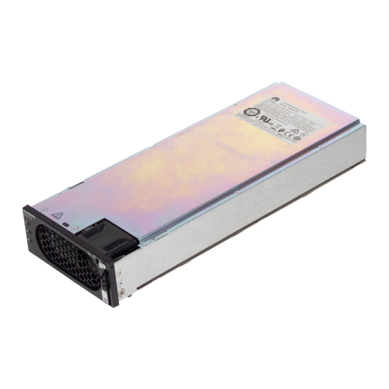
Page 51: Psu (R4875G5/R4850G5)
Integrated Smart Site (ICC1000-A1-E1) User Manual 3 Components Figure 3-20 COM port pin definitions Table 3-18 COM port pin definitions Signal Description RS485_RX+ RS485 data, positive RS485_RX- RS485 data, negative 12 V Power supply RS485_TX+ RS485 data, positive RS485_TX-... - Page 52 Integrated Smart Site (ICC1000-A1-E1) User Manual 3 Components Functions ● Converts AC power into 48 V DC power. ● Works reliably and efficiently. Table 3-19 PSU function description Item Function Hot swap Hot swappable Input protection ● Input overvoltage and undervoltage protection ●...
-
Page 53: Optional) S4875G1
Integrated Smart Site (ICC1000-A1-E1) User Manual 3 Components Indicator Color Status Description The PSU is in hibernation state. Blinking The communication between the PSU and the at 0.5 external device is interrupted. Fault indicator The PSU is proper. Steady The PSU locks out due to output overvoltage. - Page 54 Integrated Smart Site (ICC1000-A1-E1) User Manual 3 Components Indicators Table 3-21 Indicators on the S4875G1 Indicator Color State Description Suggestion Power Green Steady on The SSU has PV input. Normal status indicator The SSU has no PV input. Check that the PV input voltage is normal.
-
Page 55: Optional) Dg Battery Charger Bc-1206A
Integrated Smart Site (ICC1000-A1-E1) User Manual 3 Components 3.2.7 (Optional) DG Battery Charger BC-1206A Figure 3-23 BC-1206A exterior Figure 3-24 BC-1206A interior (1) Ground screw (2) DC input (3) Network ports (4) Surge protection board (5) Slots for the BCU-1203A... -
Page 56: Optional) Dg Battery Charger Module Bcu-1203A
Integrated Smart Site (ICC1000-A1-E1) User Manual 3 Components Technical Specifications Table 3-23 BC-1206A technical specifications Item Specifications Dimensions (H x W x D) 43.6 mm x 482.6 mm x 330 mm (including mounting ears) Weight ≤ 10 kg Input operating voltage –40 V DC to –60 V DC... - Page 57 Integrated Smart Site (ICC1000-A1-E1) User Manual 3 Components Function Description Input protection ● Protects against input undervoltage. ● Protects against input reverse connection. Output ● Protects against output current limiting. protection ● Protects against output short circuits. ● Protects against output reverse connection.
-
Page 58: Optional) Protocol Converter Unit Pcu-01A
Integrated Smart Site (ICC1000-A1-E1) User Manual 3 Components Indicator Color Normal Abnormal Reason State State Fault indicator The red indicator is on if the output is abnormal due to input overvoltage, input undervoltage, output short circuit, output reverse connection,... -
Page 59: Optional) Power Module M48500N1
Integrated Smart Site (ICC1000-A1-E1) User Manual 3 Components Item Specifications DC output Output voltage 43.2–58 V DC Output current Max. 80 A Structure Dimensions (H x 40.8 mm × 105 mm × 284 mm W x D) Surge Input port... - Page 60 Integrated Smart Site (ICC1000-A1-E1) User Manual 3 Components (4) Two 12 V DC outputs (5) Two 24 V DC outputs (6) Handle (7) ON/OFF switch (used to (8) Four 24 V AC outputs (9) Fan turn on/turn off the output)
-
Page 61: Optional) Communications Expansion Module Nim01C3
Integrated Smart Site (ICC1000-A1-E1) User Manual 3 Components Item Color Status Description Steady on ● Internal communication fails. ● The fan is faulty. ● The power module shuts down due to output overvoltage. ● The power module shuts down due to internal overtemperature. - Page 62 Integrated Smart Site (ICC1000-A1-E1) User Manual 3 Components Figure 3-28 Panel (1) SIM card slots (2 PCS) (2) 4G indicator (3) Alarm indicator (4) Run indicator (5) ANT antenna port (6) COM1 port (7) COM2 port (8) COM3/CAN port...
- Page 63 Integrated Smart Site (ICC1000-A1-E1) User Manual 3 Components Item Color Status Description Blinking fast (4 Hz) The NIM01C3 is running properly, but fails to communicate with the host. Communications Ports Table 3-31 Communications port description Communications Communications Description Port...
-
Page 64: Optional) Communications Expansion Module Cim02C
Integrated Smart Site (ICC1000-A1-E1) User Manual 3 Components Signal Description 12 V Power supply RS485+ RS485 data+ RS485- RS485 data– Reserved Reserved Ground Table 3-33 Pin definitions for the COM3/CAN port Signal Description RS485_RX+ Receives data over RS485. RS485_RX-... - Page 65 Integrated Smart Site (ICC1000-A1-E1) User Manual 3 Components Figure 3-30 Panel (1) COM1 port (2) COM2 port (3) COM3/COM4 port (4) 12 V power port (5) COM5 port (6) Handle Table 3-35 Communications port description Communications Description Communications Port...
- Page 66 Integrated Smart Site (ICC1000-A1-E1) User Manual 3 Components Table 3-36 Pin definitions for the COM1 and COM2 ports Signal Description RS485_RX+ Receives data over RS485. RS485_RX- 12 V Power supply RS485_TX+ Transmits data over RS485. RS485_TX- Reserved Reserved Ground...
-
Page 67: Optional) Dg Expansion Module Gim01C2
Integrated Smart Site (ICC1000-A1-E1) User Manual 3 Components 3.2.13 (Optional) DG Expansion Module GIM01C2 The GIM01C2 starts or shuts down a genset and supports northbound wireless communication. Figure 3-32 GIM01C2 interior (1) SIM card slot 2 (2) SIM card slot 1... - Page 68 Integrated Smart Site (ICC1000-A1-E1) User Manual 3 Components Item Color Status Description Alarm Reserved indicator (ALM) Green Steady on The dial-up connection is in indicator the data service state. (4G) Blinking at A network has been intervals of 2s (on registered.
-
Page 69: Optional) Pvdu-80A1
Integrated Smart Site (ICC1000-A1-E1) User Manual 3 Components Port Type Silk Screen Port Description Description Fuel level +12 V power Detect the fuel detection port supply level. Analog signal +12 V power supply Analog signal Communications RS485 data, Used for RS485... -
Page 70: Optional) Pvdu-150A1
Integrated Smart Site (ICC1000-A1-E1) User Manual 3 Components Table 3-41 PVDU-80A1 technical specifications Item Specifications Dimensions (H x W x 43.6 mm x 482.6 mm x 122 mm (including mounting ears) Weight 2.6 kg Input 70–150 V DC; max. 4x60 A Output 70–150 V DC;... - Page 71 Integrated Smart Site (ICC1000-A1-E1) User Manual 3 Components Figure 3-38 PVDU-150A1 interior (1) Solar input circuit breakers (2) Space for SSUs (3) Network ports (4) DC output wiring terminal (5) Ground screw Table 3-42 PVDU-150A1 technical specifications Item Specifications Dimensions (H x W x 43.6 mm x 482.6 mm x 330 mm (including mounting...
-
Page 72: Optional) Air Purifier
Integrated Smart Site (ICC1000-A1-E1) User Manual 3 Components 3.2.16 (Optional) Air Purifier Figure 3-39 Appearance (1) Wiring port NO TE In the system, the air purifier fan is fan 2. 3.2.17 (Optional) Fan Assembly (FAN-S04) Figure 3-40 Appearance (1) Wiring port NO TE The two fans in the fan assembly are fan 1 and fan 3, and they are flow fans. - Page 73 Integrated Smart Site (ICC1000-A1-E1) User Manual 3 Components Interior Figure 3-42 ETP23006-C1A1 interior (front view) (1) Power indicator (2) Fault indicator (3) COM_IN port (4) COM_OUT port (5) Ground screw (6) AC output circuit breakers (7) Inverter modules (8) -48 V DC input terminals...
-
Page 74: Dip Switch
Integrated Smart Site (ICC1000-A1-E1) User Manual 3 Components DIP Switch The DIP switches are on the rear of the embedded power subrack and horizontally placed and divided into two groups. Each group has four DIP switches, which are DIP1, DIP2, DIP3, and DIP4 from left to right. A DIP switch is set to OFF when it is... -
Page 75: Communications Port
Integrated Smart Site (ICC1000-A1-E1) User Manual 3 Components Indicator Status Description Normal Communications Port Table 3-46 Communications port description Communications Communications Communications Function Port Parameter Protocol COM_IN port Baud rate: 125 kbit/s CAN protocol Connects to an upper- level device, such as a Huawei SMU02C. -
Page 76: Inverter Module I23002G1
Integrated Smart Site (ICC1000-A1-E1) User Manual 3 Components Signal Description Pins 4 and 6 are normally open (NO), and pins 5 and 6 are normally closed (NC). CANH CAN bus high level CANL CAN bus low level 3.2.18.2 Inverter Module I23002G1 The I23002G1 is an inverter module that supports DC/AC conversion. - Page 77 Integrated Smart Site (ICC1000-A1-E1) User Manual 3 Components Indicator Table 3-50 Indicator description of an inverter module Indicator Status Description Troubleshooting Power Steady on The inverter module has DC Normal status indicator (Green) input. The inverter module has no Check that the DC voltage DC input.
-
Page 78: Optional) Ac Transfer Switch Ats-63A2
NOTE 1. Rectify a fault by referring to the preceding troubleshooting methods. 2. If the fault persists, replace the inverter module. 3. Return the faulty inverter module to Huawei for repair. 3.2.19 (Optional) AC Transfer Switch ATS-63A2 Exterior Figure 3-47 ATS exterior... - Page 79 Integrated Smart Site (ICC1000-A1-E1) User Manual 3 Components (7) SPD (8) DG 1 input circuit breakers (9) Mains/DG 2 input circuit breakers Functions The ATS is an automatic switch system integrating control and power distribution. It supports and detects the three-phase inputs from two power sources (DG 1 and mains or DG 1 and DG 2) and switches between the two power inputs.
-
Page 80: Working Mode
Integrated Smart Site (ICC1000-A1-E1) User Manual 3 Components Working Mode The ATS can work in automatic mode (AUTO) or manual mode (BYPASS). 3.2.20 (Optional) AC Distribution Unit ACDB380-63-2B The ACDB380-63-2B is used to connect to the mains and DG input. It supports three-phase four-wire AC output and single-phase AC output. -
Page 81: Optional) Power Distribution Unit Pdu2000-16-1Ph-7
Integrated Smart Site (ICC1000-A1-E1) User Manual 3 Components Item Specifications Surge protection Nominal lightning strike discharge current: 30 kA (8/20 level μs); maximum lightning strike discharge current: 60 kA (8/20 μs) IP rating IP20 3.2.21 (Optional) Power Distribution Unit PDU2000-16-1PH-7... -
Page 82: Optional) Power Distribution Unit Pdu2000-32-1Ph-9
Integrated Smart Site (ICC1000-A1-E1) User Manual 3 Components 3.2.22 (Optional) Power Distribution Unit PDU2000-32-1PH-9 Appearance and Panel Figure 3-52 Appearance of the PDU2000-32-1PH-9 Figure 3-53 PDU panel (1) Input wiring terminal (2) Switch of the power (3) AC output socket... - Page 83 Integrated Smart Site (ICC1000-A1-E1) User Manual 3 Components Appearance and Panel Figure 3-54 Appearance Figure 3-55 Panel (1) Ground screw (2) AC input terminals and (3) AC output power circuit breaker distribution (4) Surge protection alarm dry (5) PE cable busbar...
-
Page 84: Optional) Leakage Protection Box Acdb220-40-1B
Integrated Smart Site (ICC1000-A1-E1) User Manual 3 Components 3.2.24 (Optional) Leakage Protection Box ACDB220-40-1B NO TICE The RCD supports automatic switch reclosing. If you need to manually power off an RCD, you need to first switch to the manual mode. Otherwise, delayed automatic switch-on will occur in automatic mode. -
Page 85: Power Distribution Unit Dcdb48-200-16B
Integrated Smart Site (ICC1000-A1-E1) User Manual 3 Components Item Specifications Operating humidity 5%~95% (RH) Storage humidity 5%~95% (RH) Altitude 0 m~5000 m (When the altitude ranges from 2000 m to 5000 m, high temperature derating applies and the operating temperature decreases by 1°C for each additional 200 m.) -
Page 86: Dc Air Conditioner Pc3000D-2
Integrated Smart Site (ICC1000-A1-E1) User Manual 3 Components 3.2.26 DC Air Conditioner PC3000D-2 Figure 3-58 Appearance (1) Air return vent (2) Air exhaust vent (3) Communications port (4) Display panel (5) Power port Table 3-59 Specifications Item Specifications Rated power (L35/ ≤... -
Page 87: Dc Air Conditioner Pc1500D-1
Integrated Smart Site (ICC1000-A1-E1) User Manual 3 Components 3.2.27 DC Air Conditioner PC1500D-1 Figure 3-59 PC1500D-1 appearance (1) Air intake vent (2) Air return vent (3) Communications cable port (4) LCD (5) Power cable port Table 3-60 PC1500D-1 specifications... -
Page 88: Optional) Dc Heater Hau03D-01
Integrated Smart Site (ICC1000-A1-E1) User Manual 3 Components Item Specifications Noise Meets GR 487 standard; acoustic pressure level ≤ 65 dBA at 1.5 m 3.2.28 (Optional) DC Heater HAU03D-01 Appearance Figure 3-60 Appearance (1) Indicator (2) Alarm dry contact... -
Page 89: Electronic Lock
Integrated Smart Site (ICC1000-A1-E1) User Manual 3 Components Item Specifications Shutdown Heater 1: 20°C by default, configurable temperature Heater 2: 16°C by default, configurable Humidity 5%–95% RH Altitude 0–4000 m (When the altitude is between 2000 m and 4000 m, the operating temperature decreases by 1°C for each additional 200 meters.) -
Page 90: Port Definitions
Integrated Smart Site (ICC1000-A1-E1) User Manual 3 Components Electronic DIP Switch 1 DIP Switch 2 DIP Switch 3 Address Lock Port Definitions Figure 3-62 Ports on the electronic lock Table 3-63 Port definitions of the electronic lock Definitions Description... -
Page 91: Smoke Sensor
Integrated Smart Site (ICC1000-A1-E1) User Manual 3 Components 3.2.30.1 Smoke Sensor Figure 3-63 Appearance (1) Wiring port (2) Base (3) Indicator Figure 3-64 Appearance 2 (1) Wiring port (2) Base (3) Indicator 3.2.30.2 Digital Temperature and Humidity Sensor Figure 3-65 Appearance 1 Issue 04 (2022-10-15) Copyright ©... -
Page 92: Water Sensor
Integrated Smart Site (ICC1000-A1-E1) User Manual 3 Components Figure 3-66 Appearance 2 DIP Switch The following figure shows the DIP switch on a digital T/H sensor. The following table describes the DIP switch settings. Figure 3-67 DIP switch 1... -
Page 93: Vibration Sensor
Integrated Smart Site (ICC1000-A1-E1) User Manual 3 Components When the electrodes detect water, they are short-circuited and the SMU reports an alarm. Figure 3-69 Water sensor Technical Specifications Table 3-65 Water sensor specifications Category Item Specifications Environment Operating temperature –40°C to +80°C... -
Page 94: Door Status Sensor
Integrated Smart Site (ICC1000-A1-E1) User Manual 3 Components 3.2.30.5 Door Status Sensor Figure 3-71 Appearance (1) Switch (2) Magnet 3.2.31 Light Figure 3-72 Appearance 3.2.32 (Optional) Smart ETH Gateway The smart ETH gateway provides two FE ports, four PoE ports, and three –48 V power ports, and can connect to multiple communications devices such as IP cameras. - Page 95 Integrated Smart Site (ICC1000-A1-E1) User Manual 3 Components Ports Figure 3-74 Ports (1) PoE ports (2) 48V_OUT port (3) FE2 port (4) Power output port (5) Ground terminal (6) FE1 port (7) Power input port Indicators Figure 3-75 Indicators Issue 04 (2022-10-15) Copyright ©...
-
Page 96: Power Ports
Integrated Smart Site (ICC1000-A1-E1) User Manual 3 Components Table 3-66 Indicator description Name Color Status Description Power indicator Green Steady on The power input is (PWR) normal. There is no power input. Run indicator (RUN) Green Steady on Power supply is normal or data is being transmitted or received. -
Page 97: Optional) Signal Spd
Integrated Smart Site (ICC1000-A1-E1) User Manual 3 Components Table 3-68 FE and PoE port pin definitions Port Type Signal Description FE1/FE2 port Transmits data. Receives data. 4, 5, 7, 8 Reserved PoE1–PoE4 ports Transmits data. Receives data. PoE_48V 48 V power supply... - Page 98 Integrated Smart Site (ICC1000-A1-E1) User Manual 3 Components Figure 3-78 Appearance of the camera (C2120-I 2MP starlight infrared bullet camera) Figure 3-79 Interior (1) Reset button (2) SD card slot Issue 04 (2022-10-15) Copyright © Huawei Technologies Co., Ltd.
- Page 99 Integrated Smart Site (ICC1000-A1-E1) User Manual 3 Components Figure 3-80 Port description (1) Network port (2) Power input port (3) RS485 port (4) Alarm port (5) Audio port Table 3-69 Technical specifications Item Specifications Weight 0.7 kg Dimensions (H x W x D)
-
Page 100: Ess
Integrated Smart Site (ICC1000-A1-E1) User Manual 3 Components Figure 3-82 Interior and ports of camera (1) SD card slot (2) Reset button (3) Audio output port (4) Audio input port (5) Network port (6) Alarm port (7) Power input port... -
Page 101: Lithium Battery Esm-48100B1
Integrated Smart Site (ICC1000-A1-E1) User Manual 3 Components 3.3.1 Lithium Battery ESM-48100B1 Appearance Figure 3-83 ESM-48100B1 Figure 3-84 Panel and ports Table 3-72 Panel and ports description Silk Screen Item Description Protective ground M6 screw ESM dry contact Alarm output dry contact;... - Page 102 Integrated Smart Site (ICC1000-A1-E1) User Manual 3 Components Silk Screen Item Description DCHG Discharge indicator SOC indicator MANUAL Button for manual A contact button used for ON/OFF power-on/off manual power-on/off and maintenance. For details, see Activation and Startup. ESMU port for...
- Page 103 Integrated Smart Site (ICC1000-A1-E1) User Manual 3 Components Table 3-73 LED indicator description Silk Item Color Description Screen Green Steady on: Communication is normal indicator (including board startup, self-check, software loading, and board power-on when not loaded; excluding sleep when the power port or PWR port is energized).
- Page 104 Integrated Smart Site (ICC1000-A1-E1) User Manual 3 Components Silk Item Color Description Screen Green 1. 0–24% capacity indicators 25% indicator: blinking Other SOC indicators: off 2. 25%–49% capacity 25% indicator: steady on 50% indicator: blinking Other SOC indicators: off 3.
- Page 105 Integrated Smart Site (ICC1000-A1-E1) User Manual 3 Components Table 3-74 Pin definitions of communications ports RJ45 Pin Signal Description Remark RS485 T+ RS485 transmission + Four-wire RS485 communications, complying RS485 T- RS485 transmission – with the Modbus protocol Reserved...
- Page 106 Integrated Smart Site (ICC1000-A1-E1) User Manual 3 Components Silk Definition Description Alarm Status Screen Overload If the ESM raises one of the warning, following alarms, the dry contact overdischarge supplies an alarm signal: protection Discharge undervoltage alarm, discharge undervoltage protection,...
-
Page 107: Lithium Battery Esm-48100A8
Integrated Smart Site (ICC1000-A1-E1) User Manual 3 Components Item Specifications Ripple and noise ≤ 200 mV IP rating IP40 Other requirements Indoor scenario: ● There is no conductive dust, corrosive gas, or explosion hazard. ● Dust, corrosive substances, pests, molds, and other indicators should be controlled in accordance with class 3.1 requirements in ETSI EN 300 019-1-3 (V2.3.2... - Page 108 Integrated Smart Site (ICC1000-A1-E1) User Manual 3 Components Table 3-77 Port pin definitions Silk Screen Item Description Protective ground M6 screw ESM dry contact Alarm output dry contact; output configurable (if the dry contact is open, an alarm is reported by default).
- Page 109 Integrated Smart Site (ICC1000-A1-E1) User Manual 3 Components Figure 3-89 RJ45 pins Table 3-78 Pin definitions of communications ports RJ45 Pin Signal Description Remark RS485 T+ RS485 transmission + ● Four-wire RS485 communication, RS485 T- RS485 transmission – complying with the...
- Page 110 Integrated Smart Site (ICC1000-A1-E1) User Manual 3 Components DO1 and DO2 Ports Table 3-79 DO1 and DO2 port definitions Silk Definition Description Alarm Status Screen Fault, major If the ESM raises one of the Configurable alarm following alarms, the dry contact...
- Page 111 Integrated Smart Site (ICC1000-A1-E1) User Manual 3 Components Table 3-80 LED indicator description Silk Item Color Description Screen Run indicator Green Steady on: Communication is normal (including board startup, self-check, software loading, and board power-on when not loaded; excluding sleep when the power port or PWR port is energized).
- Page 112 Integrated Smart Site (ICC1000-A1-E1) User Manual 3 Components Silk Item Color Description Screen Green 1. 0–24% capacity indicators ● 25% indicator: blinking ● Other SOC indicators: off 2. 25%–49% capacity ● 25% indicator: steady on ● 50% indicator: blinking ●...
- Page 113 Integrated Smart Site (ICC1000-A1-E1) User Manual 3 Components ● Activation through the power port: supply a DC voltage of 43.2–58 V to the power terminal on the front panel for at least 5s. NO TE 1. The MANUAL ON/OFF button is a contact button. The interval for pressing the button should be greater than 0.5s;...
-
Page 114: Maintenance
Integrated Smart Site (ICC1000-A1-E1) User Manual 4 Maintenance Maintenance 4.1 Routine Maintenance Maintenance personnel perform routine maintenance periodically based on site requirements. The recommended interval is six months. If any fault is detected, rectify it in a timely manner. For details about the maintenance and troubleshooting of lithium batteries, see the corresponding lithium battery manuals. -
Page 115: Air Conditioner
Integrated Smart Site (ICC1000-A1-E1) User Manual 4 Maintenance Maintenance Item Possible Cause Suggestion Check whether the cabinet The door lock is rusty or has Replace the door lock. door lock is damaged. been tampered with. Check whether the front... - Page 116 Integrated Smart Site (ICC1000-A1-E1) User Manual 4 Maintenance Maintenance Possible Cause Troubleshooting Item The external ● The terminal is 1. Check that the power terminal of the fan is circulation fan loose. tightened. fails to start. ● The power supply 2.
-
Page 117: Ats
Integrated Smart Site (ICC1000-A1-E1) User Manual 4 Maintenance 4.1.3 ATS Table 4-3 ATS troubleshooting Symptom Alarm Possible Causes Solution Communication CAN communication ● The communications ● Reconnect the is abnormal (the interruption alarm cable is loose. communications RUN indicator cable. -
Page 118: Ac/Dc Power Distribution
Integrated Smart Site (ICC1000-A1-E1) User Manual 4 Maintenance 4.1.4 AC/DC Power Distribution Table 4-4 AC/DC power distribution maintenance Maintenance Item Possible Fault Cause Suggestion Check for AC input ● AC input power cables 1. Replace AC input power undervoltage. -
Page 119: Smu
Integrated Smart Site (ICC1000-A1-E1) User Manual 4 Maintenance Maintenance Item Possible Fault Cause Suggestion Check the yellow indicator Steady on: 1. Check the ambient status (normal: off). temperature status, and ● Because the ambient clean the cabinet air temperature is high, the channel. -
Page 120: Parameters On The Smu
Integrated Smart Site (ICC1000-A1-E1) User Manual 4 Maintenance Maintenance Item Possible Fault Cause Suggestion Check the red indicator Steady on: 1. Check related status. components based on ● A critical or major alarm alarms. is generated. 2. Replace the SMU. -
Page 121: Inverter
Integrated Smart Site (ICC1000-A1-E1) User Manual 4 Maintenance Maintenance Item Possible Fault Cause Suggestion Check whether the ● The current monitoring 1. Check that the current displayed battery charge cable is loose. monitoring cable is current is the same as the securely connected. -
Page 122: Inverter Module I23002G1
Integrated Smart Site (ICC1000-A1-E1) User Manual 4 Maintenance Symptom Possible Cause Suggestion The fault indicator is ● The SPD is faulty. ● Replace the inverter. steady red. ● A power frequency ● Check whether the edge connectors of the... -
Page 123: Routine Maintenance For Esms
Integrated Smart Site (ICC1000-A1-E1) User Manual 4 Maintenance Maintenance Item Possible Fault Cause Suggestion Check whether the DC RTN The DC RTN+ busbar is not Connect the ground cable to + busbar is grounded. properly grounded. the DC RTN+ busbar properly. -
Page 124: Identifying Component Faults
Integrated Smart Site (ICC1000-A1-E1) User Manual 4 Maintenance Maintenance Maintenance Measure Interval Item Connection Check the bolt at every terminal and tighten any loose bolt. If a cable temperature exceeds 40°C (feels hot), locate the cause. Semi-annual Voltage ● Measure and record the busbar voltage and the positive and negative voltages of ESMs when charging is about to complete. -
Page 125: Identifying Circuit Breaker Faults
Integrated Smart Site (ICC1000-A1-E1) User Manual 4 Maintenance 4.2.3 Identifying Circuit Breaker Faults If the load fuse is blown, it indicates that the circuit breaker trips. If the circuit breaker is switched on and the downstream device is still not powered (the busbar has power), the circuit breaker is faulty and needs to be replaced. -
Page 126: Replacing Components
Integrated Smart Site (ICC1000-A1-E1) User Manual 4 Maintenance 4.3 Replacing Components NO TICE ● Ensure that loads are supplied with power when replacing major components. For example, keep the switches for primary loads in the ON position, and do not turn off the battery switch and AC input switch at the same time. -
Page 127: Replacing A Uim05B1
Integrated Smart Site (ICC1000-A1-E1) User Manual 4 Maintenance Figure 4-2 Installing the SMU02C Step 7 Reconnect the communications cable to the SMU02C panel based on the recorded information. Step 8 Set SMU02C parameters. NO TE After installing the new SMU, power on the SMU and check the software version of the new SMU. -
Page 128: Replacing A R4875G5/R4850G5
Integrated Smart Site (ICC1000-A1-E1) User Manual 4 Maintenance Figure 4-3 Removing the UIM05B1 Step 4 Install the new UIM05B1. Step 5 Install the cables based on the recorded information. Step 6 Disconnect the ground cable from the ESD wrist strap, and remove the ESD wrist strap and ESD gloves. -
Page 129: Replacing An S4875G1
Figure 4-5 Installing a rectifier Step 7 Take off protective gloves. ----End Follow-up Procedure Pack the removed component, and return it to Huawei local warehouse. 4.3.4 Replacing an S4875G1 Prerequisites ● You have obtained a pair of protective gloves, the cabinet door key, and a toolkit. - Page 130 Integrated Smart Site (ICC1000-A1-E1) User Manual 4 Maintenance Procedure Step 1 Put on protective gloves. Step 2 Switch off the PVDU circuit breaker and remove cables from the SSU and label it. Step 3 Push the locking latch at the right side of the SSU panel towards the left.
-
Page 131: Replacing An M48500N1
Integrated Smart Site (ICC1000-A1-E1) User Manual 4 Maintenance Step 8 Reconnect the cables labelled to the new SSU and switch on the PVDU circuit breaker. Step 9 Take off the protective gloves. ----End Follow-up Procedure Pack the removed component, and return it to the local warehouse. -
Page 132: Replacing A Bcu-1203A
Integrated Smart Site (ICC1000-A1-E1) User Manual 4 Maintenance Step 7 Insert the new M48500N1 module into the slot, push the locking latch to the left, and pull out the handle. Step 8 Gently push the M48500N1 module along the guide rails into the subrack. Close the handle, and push the locking latch to the right. -
Page 133: Replacing A Bc-1206A
Integrated Smart Site (ICC1000-A1-E1) User Manual 4 Maintenance CA UTION To prevent burns, exercise caution when removing a BCU-1203A because it may be hot as a result of continuous operation. Procedure Step 1 Wear protective gloves. Step 2 Record the connection positions of cables on the BCU-1203A and remove the cables. -
Page 134: Replacing A Cim02C
Integrated Smart Site (ICC1000-A1-E1) User Manual 4 Maintenance Step 3 Remove the BCU-1203A. Step 4 Remove the faulty BC-1206A. Step 5 Install the new BC-1206A. Figure 4-13 Installing a new BC-1206A Step 6 Install the removed BCU-1203A on the new BC-1206A. -
Page 135: Replacing A Nim01C3
Integrated Smart Site (ICC1000-A1-E1) User Manual 4 Maintenance Figure 4-14 Removing the CIM02C Step 5 Place the new CIM02C into the correct slot in the subrack, and push the CIM02C until its front panel is flush with the front panel of the subrack. - Page 136 Integrated Smart Site (ICC1000-A1-E1) User Manual 4 Maintenance Step 3 Loosen the screws on both sides of the communications expansion module. Step 4 Pull the handle rightwards and remove the communications expansion module. Figure 4-16 Removing a communications expansion module Step 5 Remove the SIM card from the SIM card slot, and insert the new communications expansion module.
-
Page 137: Replacing A Dg Expansion Module Gim01C
Integrated Smart Site (ICC1000-A1-E1) User Manual 4 Maintenance 4.3.10 Replacing a DG Expansion Module GIM01C Prerequisites ● The ESD wrist strap, ESD gloves, and key to the cabinet door are available. ● The new GIM01C is intact. Procedure Step 1 Connect the ground cable of the ESD wrist strap, and wear the ESD wrist strap and ESD gloves. - Page 138 Integrated Smart Site (ICC1000-A1-E1) User Manual 4 Maintenance ● You are authorized to enter the site with the key. Context An inverter needs to be replaced if it is faulty and cannot be repaired immediately. Procedure Step 1 Wear an ESD wrist strap or ESD gloves.
-
Page 139: Replacing An Inverter Module I23002G1
Integrated Smart Site (ICC1000-A1-E1) User Manual 4 Maintenance Step 7 Connect the cables to the inverter based on the recorded information. Step 8 Remove the ESD wrist strap or gloves and put all the tools away. ----End Follow-up Procedure Pack the removed components and send them to the local warehouse. -
Page 140: Replacing An Ats Main Control Box
Integrated Smart Site (ICC1000-A1-E1) User Manual 4 Maintenance Figure 4-22 Installing a new inverter module Step 7 Remove the protective gloves. ----End Follow-up Procedure Pack the removed components and send them to the local warehouse. 4.3.13 Replacing an ATS Main Control Box The ATS main control box needs to be replaced if it is faulty and cannot be repaired immediately. - Page 141 Integrated Smart Site (ICC1000-A1-E1) User Manual 4 Maintenance Step 3 Disconnect cables from the faulty ATS main control box. Insulate each cable and label it immediately after disconnecting it. Step 4 Remove the faulty ATS main control box and install the replacement main control box, as shown in the following figure.
-
Page 142: Replacing An Acdb380-63-2B
ESD box or bag into the carbon box with foams or the bag of a new component. ● Fill in the fault card with the information regarding the faulty component. ● Contact your local Huawei office to handle the faulty component. 4.3.14 Replacing an ACDB380-63-2B Perform the following steps to replace an ACDB380-63-2B. Prerequisites ●... -
Page 143: Replacing A Pdu2000-16-1Ph-7
Integrated Smart Site (ICC1000-A1-E1) User Manual 4 Maintenance Figure 4-25 Installing an ACDB380-63-2B Step 5 Connect the cables to the ACDB380-63-2B based on the recorded information. Step 6 Remove the ESD wrist strap or gloves and put all the tools away. -
Page 144: Replacing An Acdb220-63-12B
Integrated Smart Site (ICC1000-A1-E1) User Manual 4 Maintenance Figure 4-26 Removing a PDU2000 Step 6 Install the new PDU2000. Step 7 Open the cover on the PDU2000 input wiring terminals. Step 8 Install the PDU2000 ground cable. Step 9 Connect one end of the PDU2000 input cable to the PDU2000 input terminal and the other end to the ACDB220-63-12B output terminal. -
Page 145: Replacing An Acdb220-40-1B
Integrated Smart Site (ICC1000-A1-E1) User Manual 4 Maintenance Figure 4-27 Removing an ACDB220-63-12B Step 4 Install a new ACDB220-63-12B. Figure 4-28 Installing an ACDB220-63-12B Step 5 Connect the cables to the ACDB220-63-12B based on the recorded information. Step 6 Remove the ESD wrist strap or gloves and put all the tools away. - Page 146 Integrated Smart Site (ICC1000-A1-E1) User Manual 4 Maintenance Procedure Step 1 Connect the ESD wrist strap ground cable, and wear the ESD wrist strap and ESD gloves. Step 2 Remove the baffle plate. Figure 4-29 Removing the baffle plate Step 3 Record the cable connection of the automatic reclosing residual current device (RCD) to be replaced, and disconnect the cables.
-
Page 147: Replacing An Esm
Integrated Smart Site (ICC1000-A1-E1) User Manual 4 Maintenance Step 7 Install the baffle plate. Step 8 Remove the ESD wrist strap or gloves and put all the tools away. ----End 4.3.18 Replacing an ESM Prerequisites ● The protective gloves, Phillips screwdriver and socket wrench are available. - Page 148 Integrated Smart Site (ICC1000-A1-E1) User Manual 4 Maintenance Step 4 Loosen the screws on the panel and remove the ESM. Figure 4-31 Removing the old ESM ----End Installing the New ESM Step 1 Install the new ESM and tighten the screws.
-
Page 149: Replacing An Air Conditioner Pc3000D-2
● Fill in the fault card with the information about the removed component. ● Contact your local Huawei office to handle the faulty component. 4.3.19 Replacing an Air Conditioner PC3000D-2 Prerequisites ●... - Page 150 Integrated Smart Site (ICC1000-A1-E1) User Manual 4 Maintenance Context You need only to disconnect the air conditioner power supply, but not the AC input to the system. Procedure Step 1 Connect the ground cable of the ESD wrist strap, and wear the ESD wrist strap and ESD gloves.
- Page 151 Integrated Smart Site (ICC1000-A1-E1) User Manual 4 Maintenance Figure 4-35 Installing the new air conditioner Step 6 Apply sealant on the air conditioner rubber strip and the position where the air conditioner passes through the cabinet. Step 7 Reconnect the removed cables to the new air conditioner based on the recorded information.
-
Page 152: Replacing An Air Conditioner Pc1500D-1
Integrated Smart Site (ICC1000-A1-E1) User Manual 4 Maintenance Follow-up Procedure Send the removed air conditioner for repair. 4.3.20 Replacing an Air Conditioner PC1500D-1 Prerequisites ● You have obtained an ESD wrist strap, a pair of ESD gloves, a Phillips screwdriver, a wrench, an ESD bag, and the cabinet door key. - Page 153 Integrated Smart Site (ICC1000-A1-E1) User Manual 4 Maintenance Step 5 Install the new air conditioner. Figure 4-37 Installing the new air conditioner Step 6 Apply sealant on the air conditioner rubber strip and the position where the air conditioner passes through the cabinet.
-
Page 154: Replacing An Hau03D-01
Integrated Smart Site (ICC1000-A1-E1) User Manual 4 Maintenance Follow-up Procedure Send the removed air conditioner for repair. 4.3.21 Replacing an HAU03D-01 Prerequisites ● Tools and the key to the cabinet door are available. ● The new heater is intact. -
Page 155: Replacing An Electronic Lock
Integrated Smart Site (ICC1000-A1-E1) User Manual 4 Maintenance Figure 4-40 Installing a heater on the rack Step 6 Connect the cables to the heater based on the recorded information. Step 7 Switch on the heater circuit breaker on the DCDU. - Page 156 Integrated Smart Site (ICC1000-A1-E1) User Manual 4 Maintenance Step 4 Unscrew the electronic lock cover, and remove the lock. Figure 4-42 Removing an electronic lock (1) Lock (2) Lock cover Step 5 Record the DIP switch settings of the electronic door lock.
- Page 157 Integrated Smart Site (ICC1000-A1-E1) User Manual 4 Maintenance Figure 4-43 Removing the bolt Remove the shaft sleeve from the lock. Figure 4-44 Removing the shaft sleeve Rotate the positioning kit according to the door opening direction. NO TE If the ears on the positioning kit are horizontal, the door is right-handed. If they are vertical, the door is left-handed.
-
Page 158: Replacing A Smoke Sensor
Integrated Smart Site (ICC1000-A1-E1) User Manual 4 Maintenance Figure 4-45 Rotating the positioning kit Reinstall the shaft sleeve and bolt. Step 9 Remove the other screws from the lock, reinstall the lock on the cabinet door, and tighten screws on the lock cover. - Page 159 Integrated Smart Site (ICC1000-A1-E1) User Manual 4 Maintenance ● The new smoke sensor is intact. Procedure Step 1 Connect the ground cable to the ESD wrist strap, and put on the ESD wrist strap and ESD gloves. Step 2 Remove the smoke sensor.
-
Page 160: Replacing A Digital Temperature And Humidity Sensor
Integrated Smart Site (ICC1000-A1-E1) User Manual 4 Maintenance 4.3.24 Replacing a Digital Temperature and Humidity Sensor Prerequisites ● Tools and the key to the cabinet door are available. ● The new digital temperature and humidity sensor is intact. Procedure Step 1 Record cable information and installation positions. -
Page 161: Replacing A Door Status Sensor
Integrated Smart Site (ICC1000-A1-E1) User Manual 4 Maintenance ● The new water sensor is intact. Procedure Step 1 Connect the ground cable to the ESD wrist strap, and put on the ESD wrist strap and ESD gloves. Step 2 Disconnect the water sensor from the UIM. -
Page 162: Replacing A Light
Integrated Smart Site (ICC1000-A1-E1) User Manual 4 Maintenance Step 4 Remove the shell of the new door status sensor and remove the screws from the signal cables. Step 5 Properly place a new door sensor at the installation position and tighten the screws. -
Page 163: Replacing A Smart Eth Gateway
Integrated Smart Site (ICC1000-A1-E1) User Manual 4 Maintenance Figure 4-50 Install a light ----End Follow-up Procedure Pack the removed component and send it to the local warehouse. 4.3.28 Replacing a Smart ETH Gateway Prerequisites ● An ESD wrist strap, ESD gloves, ESD box or bag, door key, and required tools are available. -
Page 164: Replacing A Circuit Breaker
Integrated Smart Site (ICC1000-A1-E1) User Manual 4 Maintenance Connect the gateway power cable. Step 7 Set the circuit breaker corresponding to the smart ETH gateway to ON. Step 8 Disconnect the ground cable from the ESD wrist strap, and remove the ESD wrist strap and ESD gloves. -
Page 165: Replacing An Ac Input Module
Integrated Smart Site (ICC1000-A1-E1) User Manual 4 Maintenance 4.3.30 Replacing an AC Input Module Prerequisites The required tools are available and the new AC input module is intact. NO TICE ● Power off the AC input module before replacing it. - Page 166 Integrated Smart Site (ICC1000-A1-E1) User Manual 4 Maintenance D ANGER Do not replace an AC SPD module during a thunderstorm. Procedure Step 1 Connect the ground cable to the ESD wrist strap and wear the ESD wrist strap and ESD gloves Step 2 Hold down the faulty AC SPD module and pull it out.
-
Page 167: Technical Specifications
Integrated Smart Site (ICC1000-A1-E1) User Manual A Technical Specifications Technical Specifications A.1 Environmental Specifications Table A-1 Environmental Specifications Item Specifications Operating temperature –40ºC to +55ºC with 1120 W/m solar radiation Transport temperature –40ºC to +70ºC Storage temperature –40ºC to +70ºC Relative humidity 5%–98% RH... -
Page 168: Electrical Specifications
Integrated Smart Site (ICC1000-A1-E1) User Manual A Technical Specifications A.2 Electrical Specifications Table A-2 Electrical Specifications Item Specifications AC input Input system ● ETP48400-C3B1: 220/380 V AC three-phase four-wire, compatible with 220 V AC single- phase ● ETP48400-C3B3: 220/380 V AC three-phase... -
Page 169: Emc Specifications
Integrated Smart Site (ICC1000-A1-E1) User Manual A Technical Specifications Item Specifications Safety design IEC 60950-1, IEC 62368-1 MTBF 200,000 hours (at 25ºC) A.3 EMC Specifications Table A-3 EMC specifications Item Specifications Electromagnetic Conducted emission EN 55032 interference (EMI) (CE) AC port: Class A;... - Page 170 Integrated Smart Site (ICC1000-A1-E1) User Manual A Technical Specifications Item Specifications Surge susceptibility IEC 61000-4-5 ● AC power port: 6 kV (horizontal), 1.2/50 μs, 2 ohms (criterion B); 6 kV (vertical, two wires to ground), 1.2/50 μs, 2 ohms (criterion B) ●...
-
Page 171: B Electrical Conceptual Diagrams
Integrated Smart Site (ICC1000-A1-E1) User Manual B Electrical Conceptual Diagrams Electrical Conceptual Diagrams Figure B-1 ETP48400-C3B3 electrical conceptual diagram Figure B-2 ETP48400-C3B1 electrical conceptual diagram Issue 04 (2022-10-15) Copyright © Huawei Technologies Co., Ltd. -
Page 172: C Power Distribution Of Circuit Breakers On The Power Subrack
Integrated Smart Site (ICC1000-A1-E1) C Power Distribution of Circuit Breakers on the User Manual Power Subrack Power Distribution of Circuit Breakers on the Power Subrack The description in the following table is for reference only. The actual cable connection prevails. -
Page 173: D Device Address Description
Integrated Smart Site (ICC1000-A1-E1) User Manual D Device Address Description Device Address Description The following are the default addresses of the device. The actual addresses prevail. Table D-1 Address description Item Component Address Remarks ICC1000-A1-E1 DC air conditioner (upper front Address range: 21–30... -
Page 174: E Associations Between Alarms And Dry Contacts On The Uim
Integrated Smart Site (ICC1000-A1-E1) E Associations Between Alarms and Dry Contacts on User Manual the UIM Associations Between Alarms and Dry Contacts on the UIM Table E-1 Associations between dry contacts and alarms Dry Contact Type Silkscreen Associated Alarm... -
Page 175: F How Do Change The Communications Protocol For Com4 And Com5
Integrated Smart Site (ICC1000-A1-E1) F How Do Change the Communications Protocol for User Manual COM4 and COM5? How Do Change the Communications Protocol for COM4 and COM5? ● To use CAN for communication through the COM4 port: Take out the CIM02C, remove the jumper caps from pins 1 and 2 in the J18... - Page 176 Integrated Smart Site (ICC1000-A1-E1) F How Do Change the Communications Protocol for User Manual COM4 and COM5? Figure F-2 Jumper connection rules for the COM4 and COM5 ports Issue 04 (2022-10-15) Copyright © Huawei Technologies Co., Ltd.
-
Page 177: G Operating Environment Definitions
Integrated Smart Site (ICC1000-A1-E1) User Manual G Operating Environment Definitions Operating Environment Definitions Table G-1 Operating environment definitions Class Environment Definition Class A Indoor environments where temperature and humidity are controllable, including rooms where human beings live. Class B... -
Page 178: Acronyms And Abbreviations
Integrated Smart Site (ICC1000-A1-E1) User Manual H Acronyms and Abbreviations Acronyms and Abbreviations BLVD Battery low voltage disconnection Electromagnetic compatibility Electromagnetic interference Electromagnetic susceptibility HTTPS Hypertext Transfer Protocol Secure LLVD Load low voltage disconnection International Electrotechnical Commission MTBF Mean time between failures... - Page 179 Integrated Smart Site (ICC1000-A1-E1) User Manual H Acronyms and Abbreviations User interface module Issue 04 (2022-10-15) Copyright © Huawei Technologies Co., Ltd.
Need help?
Do you have a question about the iSitePower and is the answer not in the manual?
Questions and answers