
Related Manuals for Huawei iSitePower-M V100R002C00


Summary of Contents for Huawei iSitePower-M V100R002C00
- Page 1 V100R002C00 (MAP15A1, MAB05B1) User Manual Issue Date 2021-09-30 HUAWEI DIGITAL POWER TECHNOLOGIES CO., LTD.
- Page 2 Notice The purchased products, services and features are stipulated by the contract made between Huawei Digital Power Technologies Co., Ltd. and the customer. All or part of the products, services and features described in this document may not be within the purchase scope or the usage scope. Unless otherwise speci ied in the contract, all statements, information, and recommendations in this document are provided "AS IS"...
-
Page 3: Table Of Contents
5.2 Installing a Mounting Bracket............................37 5.2.1 Ground Mounting................................37 5.2.2 Wall Mounting..................................40 5.3 Installing Modules................................42 5.4 (Optional) Installing Battery Modules for Capacity Expansion................44 5.5 (Optional) Installing a Wireless Backhaul Module....................46 Issue 01 (2021-09-30) Copyright © Huawei Digital Power Technologies Co., Ltd. - Page 4 9.3 Tools for Preparing PV Cables............................89 9.4 Special Cables..................................89 9.5 Removing Power Terminals............................... 89 9.6 Power-On....................................90 9.7 SOC Changes..................................90 9.8 Checking Cable Connections when the Product Fails to Be Upgraded.............. 90 Issue 01 (2021-09-30) Copyright © Huawei Digital Power Technologies Co., Ltd.
- Page 5 9.11 Conflict Between the LAN IP Address of the Router and the IP Address of the Product......90 9.12 Problem Handling................................91 A Technical Specifications.......................92 A.1 Environmental Specifications............................92 A.2 Electrical Specifications..............................93 A.3 EMC Specifications................................94 Issue 01 (2021-09-30) Copyright © Huawei Digital Power Technologies Co., Ltd.
-
Page 6: About This Document
Indicates a potentially hazardous situation which, if not avoided, could result in equipment damage, data loss, performance deterioration, or unanticipated results. NOTICE is used to address practices not related to personal injury. Issue 01 (2021-09-30) Copyright © Huawei Digital Power Technologies Co., Ltd. - Page 7 Change History Changes between document issues are cumulative. The latest document issue contains all updates made in previous issues. Issue 01 (2021-09-30) This is the first official release. Issue 01 (2021-09-30) Copyright © Huawei Digital Power Technologies Co., Ltd.
-
Page 8: Safety Precautions
Equipment damage due to force majeure, such as earthquakes, fire, and storms ● Damage caused during transportation by the customer ● Damage caused by storage conditions that do not meet the requirements specified in related documents Issue 01 (2021-09-30) Copyright © Huawei Digital Power Technologies Co., Ltd. - Page 9 Therefore, avoid touching the battery. ● Do not disassemble or damage the battery. The released electrolyte is harmful to your skin and eyes. Avoid contact with the electrolyte. Issue 01 (2021-09-30) Copyright © Huawei Digital Power Technologies Co., Ltd.
- Page 10 If a fire occurs, power off the system if it is safe to do so. ● Extinguish the fire with carbon dioxide, FM-200 or ABC dry powder fire extinguishers. Issue 01 (2021-09-30) Copyright © Huawei Digital Power Technologies Co., Ltd.
-
Page 11: Personnel Requirements
● Only professionals or authorized personnel are allowed to replace the equipment or components (including software). Issue 01 (2021-09-30) Copyright © Huawei Digital Power Technologies Co., Ltd. -
Page 12: Electrical Safety
● Before connecting cables, switch off the disconnector on the upstream equipment to cut off the power supply if people may contact energized components. Issue 01 (2021-09-30) Copyright © Huawei Digital Power Technologies Co., Ltd. -
Page 13: Installation Environment Requirements
● Do not expose the battery to flammable or explosive gas or smoke. Do not perform any operation on the battery in such environments. Issue 01 (2021-09-30) Copyright © Huawei Digital Power Technologies Co., Ltd. -
Page 14: Transportation Requirements
Protect the packing case with the product from the following situations: ● Being dampened by rains, snows, or falling into water ● Falling or mechanical impact Issue 01 (2021-09-30) Copyright © Huawei Digital Power Technologies Co., Ltd. -
Page 15: Mechanical Safety
Ensure that your body's center of gravity does not shift outside the legs of the ladder. Drilling Holes When drilling holes into a wall or ground, observe the following safety precautions: ● Wear goggles and protective gloves when drilling holes. Issue 01 (2021-09-30) Copyright © Huawei Digital Power Technologies Co., Ltd. -
Page 16: Commissioning
Before maintaining the equipment, check that no hazardous voltages remain in the DC bus or components to be maintained by using a multimeter. Issue 01 (2021-09-30) Copyright © Huawei Digital Power Technologies Co., Ltd. - Page 17 Take out all tools and parts from the equipment after maintenance is complete. ● If the equipment is not used for a long time, store and recharge batteries according to this document. Issue 01 (2021-09-30) Copyright © Huawei Digital Power Technologies Co., Ltd.
-
Page 18: Product Description
– A cloud data management system is used to manage the system anytime and anywhere. ● Less investment – Only common installation tools required Issue 01 (2021-09-30) Copyright © Huawei Digital Power Technologies Co., Ltd. -
Page 19: Scenario Configuration
3 Product Description – High efficiency and power density, less installation space – Easy O&M 3.2 Scenario Configuration Figure 3-1 Networking diagram The system supports capacity expansion and power expansion. Issue 01 (2021-09-30) Copyright © Huawei Digital Power Technologies Co., Ltd. - Page 20 V100R002C00 (MAP15A1, MAB05B1) User Manual 3 Product Description Figure 3-2 System configurations Issue 01 (2021-09-30) Copyright © Huawei Digital Power Technologies Co., Ltd.
-
Page 21: Appearance
Ground-mounted and wall-mounted Input voltage 200/220/230/240 V AC, default value: 220 V AC Input Input current Maximum current: 30 A Input capacity 6 kVA Open-circuit 85–435 V DC input voltage Issue 01 (2021-09-30) Copyright © Huawei Digital Power Technologies Co., Ltd. - Page 22 Bypass input frequency 6 kW Application environment Class C environment Ingress protection (IP) IP65 rating Figure 3-4 LED indicators (1) Annular strip light (2) Running indicator (3) WiFi indicator Issue 01 (2021-09-30) Copyright © Huawei Digital Power Technologies Co., Ltd.
- Page 23 A part of the strip light dims when every 10% of battery power is consumed. Blinking green at Indicates that the product is being charging. an interval of 1.25s Issue 01 (2021-09-30) Copyright © Huawei Digital Power Technologies Co., Ltd.
-
Page 24: Components
Figure 4-2 Ports on the power module (1) PV maintenance switch (DC (2) PV inputs (3) Power parallel ports for SWITCH) battery modules (4) COM-PAR port (5) COM-BAT port (6) AC input ports Issue 01 (2021-09-30) Copyright © Huawei Digital Power Technologies Co., Ltd. - Page 25 Dry contact output common terminal DO_NC Dry contact output normally closed (NC) terminal Null Null DO_NO Dry contact output NO terminal DO_COM Dry contact output common terminal DO_NC Dry contact output NC terminal Issue 01 (2021-09-30) Copyright © Huawei Digital Power Technologies Co., Ltd.
- Page 26 ● When only one product is used, set Pin 1 to ON. ● The default address is 0 (Pin 1 to Pin 4: OFF). COM and Dry Contacts Figure 4-5 Wiring terminals Issue 01 (2021-09-30) Copyright © Huawei Digital Power Technologies Co., Ltd.
- Page 27 WiFi SSID and password. Communications Ports Table 4-4 Communications port description Port Communications Communications Function Parameter Protocol COM-PAR Baud rate: 1 Mbit/s CAN protocol Parallel communications port for power modules Issue 01 (2021-09-30) Copyright © Huawei Digital Power Technologies Co., Ltd.
- Page 28 2– Synchronization signal 3+ Synchronization signal 3– CANH Parallel high-speed CAN CANL Table 4-6 COM-BAT pin definitions Signal Description START+ Black start switch START- 3, 4, 5, 6 Null Issue 01 (2021-09-30) Copyright © Huawei Digital Power Technologies Co., Ltd.
-
Page 29: Battery Module
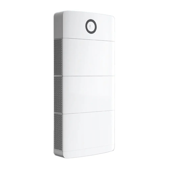
Table 4-7 Pin definitions for the FE port Signal Description Transmit data over FE. Receive data over FE. 4, 5, 7, 8 Null 4.2 Battery Module The standard capacity is 5 kWh. Figure 4-6 Appearance Issue 01 (2021-09-30) Copyright © Huawei Digital Power Technologies Co., Ltd. - Page 30 The preceding port is protected by security mechanisms. Table 4-9 COM pin definition Signal Description START+ Black start button START- Null Null Null Null CANH CAN bus high level Issue 01 (2021-09-30) Copyright © Huawei Digital Power Technologies Co., Ltd.
-
Page 31: Optional) Ac Parallel Box Acdb220-90-1B
(4) N wiring terminal (5) AC output circuit breaker (6) Cable bags Table 4-10 Specifications Item Specifications Dimensions (H x W 450 mm x 350 mm x 150 mm x D) Issue 01 (2021-09-30) Copyright © Huawei Digital Power Technologies Co., Ltd. -
Page 32: Optional) Backhaul Module Iiot-Wac0411
1.7s service, the service is restricted, or the Blinking slowly: at an interval network is being of 2s, on for 0.2s and off for searched. 1.8s alternately Issue 01 (2021-09-30) Copyright © Huawei Digital Power Technologies Co., Ltd. - Page 33 Figure 4-11 Port pins on the wireless backhaul module Table 4-12 Port pin definition for the wireless backhaul module Signal Description VBUS Power supply GND1 Power ground STDA_RX- Signal STDA_RX+ Signal GND2 STDA_TX- Signal STDA_TX+ Signal Issue 01 (2021-09-30) Copyright © Huawei Digital Power Technologies Co., Ltd.
-
Page 34: Optional) Backhaul Module Iiot-Wac0412
Figure 4-12 Backhaul module (1) Indicator (2) SIM card installation (3) Module installation port position Issue 01 (2021-09-30) Copyright © Huawei Digital Power Technologies Co., Ltd. - Page 35 Figure 4-13 Pins on the port of the wireless backhaul module (male, backhaul module side) Table 4-15 Port pin definition for the wireless backhaul module Signal Description VBUS Power supply GND1 Power ground STDA_RX- Signal STDA_RX+ Signal Issue 01 (2021-09-30) Copyright © Huawei Digital Power Technologies Co., Ltd.
- Page 36 824 MHz–849 MHz 869 MHz–894 MHz GSM 900 880 MHz–915 MHz 925 MHz–960 MHz GSM 1800 1710 MHz–1785 MHz 1805 MHz–1880 MHz GSM 1900 1850 MHz–1910 MHz 1930 MHz–1990 MHz Issue 01 (2021-09-30) Copyright © Huawei Digital Power Technologies Co., Ltd.
-
Page 37: System Installation
For details about the number of deliverables, see the Packing List in the packing case. 5.1.2 Tools and Instruments Type Tools and Instruments Installation Hammer drill Torque socket Torque wrench wrench Issue 01 (2021-09-30) Copyright © Huawei Digital Power Technologies Co., Ltd. - Page 38 PV-CZM- crimping tool (model: PV-MS- CZM41100 HZ open-end (preferred)/ wrench) CZM22100 Cable tie Vacuum cleaner Multimeter (DC voltage measurement range ≥ 600 V Marker Steel measuring Level tape Issue 01 (2021-09-30) Copyright © Huawei Digital Power Technologies Co., Ltd.
-
Page 39: Determining The Installation Position
The product can be ground-mounted and wall-mounted. The installation angle requirement is as follow: ● Do not install the product at forward tilted, back tilted, side tilted, horizontal, or upside down positions. Issue 01 (2021-09-30) Copyright © Huawei Digital Power Technologies Co., Ltd. - Page 40 The bearing capacity of the ground must be greater than or equal to 500 kg/m Installation Dimensions Reserve sufficient clearance around the product for installation and heat dissipation. Figure 5-1 Installation dimensions for one product Issue 01 (2021-09-30) Copyright © Huawei Digital Power Technologies Co., Ltd.
-
Page 41: Backfeed Protection Device Specifications
To reduce the risk of electric shocks caused by reverse feeding, install a backfeed protection device for the AC input of the iSitePower-M. Issue 01 (2021-09-30) Copyright © Huawei Digital Power Technologies Co., Ltd. -
Page 42: Installing A Mounting Bracket
Two marking-off templates are required for ground mounting. A small marking-off template determines holes on the ground, and a large marking-off template determines holes on the wall. Step 1 Cut the large marking-off template along the dotted line. Issue 01 (2021-09-30) Copyright © Huawei Digital Power Technologies Co., Ltd. - Page 43 Then, use a marker to mark the positions. Step 3 Install the mounting base. D ANGER When drilling holes, avoid the water pipes and power cables buried in the wall. Issue 01 (2021-09-30) Copyright © Huawei Digital Power Technologies Co., Ltd.
- Page 44 (the weight of one battery module is 50 kg) are met and appropriate bolts are selected. Issue 01 (2021-09-30) Copyright © Huawei Digital Power Technologies Co., Ltd.
-
Page 45: Wall Mounting
● Use the M6x60 expansion bolts delivered with the product to secure the modules. If the length or quantity of the expansion bolts cannot meet the installation requirements, prepare M6 stainless steel expansion bolts by yourself. Issue 01 (2021-09-30) Copyright © Huawei Digital Power Technologies Co., Ltd. - Page 46 V100R002C00 (MAP15A1, MAB05B1) User Manual 5 System Installation Figure 5-6 Wall mounting Step 3 Install a wall-mounting bracket cover. Issue 01 (2021-09-30) Copyright © Huawei Digital Power Technologies Co., Ltd.
-
Page 47: Installing Modules
● Battery modules must be secured to the wall. NO TE This section describes how to install modules in the ground mounting scenario. Installing Modules Step 1 Install the battery module on the base. Issue 01 (2021-09-30) Copyright © Huawei Digital Power Technologies Co., Ltd. - Page 48 V100R002C00 (MAP15A1, MAB05B1) User Manual 5 System Installation Figure 5-8 Installing a battery module Step 2 Secure the battery module to the wall. Figure 5-9 Securing the battery module Issue 01 (2021-09-30) Copyright © Huawei Digital Power Technologies Co., Ltd.
-
Page 49: Optional) Installing Battery Modules For Capacity Expansion
● For details about how to install brackets and modules, see 5.2 Installing a Mounting Bracket 5.3 Installing Modules. Issue 01 (2021-09-30) Copyright © Huawei Digital Power Technologies Co., Ltd. - Page 50 Step 1 Rotate the L-shaped sheets on the top cover by 180 degrees. Figure 5-10 Rotating the L-shaped sheets on the top cover Step 2 Install the top cover on the battery module. Issue 01 (2021-09-30) Copyright © Huawei Digital Power Technologies Co., Ltd.
-
Page 51: Optional) Installing A Wireless Backhaul Module
● When removing the SIM card, push it inwards to eject it. ● If you hear two clicks when installing a backhaul module, the module is properly installed. If the module is not properly installed, water may enter. Issue 01 (2021-09-30) Copyright © Huawei Digital Power Technologies Co., Ltd. -
Page 52: Optional) Installing An Ac Parallel Box
5.6 (Optional) Installing an AC Parallel Box Prerequisites In a parallel system, an AC parallel box must be configured. Step 1 Mark mounting holes. Figure 5-13 Marking mounting holes Step 2 Install expansion bolts. Issue 01 (2021-09-30) Copyright © Huawei Digital Power Technologies Co., Ltd. - Page 53 V100R002C00 (MAP15A1, MAB05B1) User Manual 5 System Installation Figure 5-14 Installing expansion bolts Step 3 Install the AC parallel box on the wall. Figure 5-15 Installing the AC parallel box ----End Issue 01 (2021-09-30) Copyright © Huawei Digital Power Technologies Co., Ltd.
-
Page 54: Electrical Connection
Select cables in accordance with local cable specifications (green and yellow cables are only used for PE). 6.1 Preparing Cables NO TICE Do not use aluminum cables to avoid electrochemical corrosion of copper and aluminum. Issue 01 (2021-09-30) Copyright © Huawei Digital Power Technologies Co., Ltd. - Page 55 6 mm Dry contact Outdoor shielded ● Conductor Prepared signal cable twisted pair cable cross-sectional by the (8 cores) customer area: 0.2–1 mm ● Cable outer diameter: 6.3– 7.5 mm Issue 01 (2021-09-30) Copyright © Huawei Digital Power Technologies Co., Ltd.
- Page 56 ● Cable outer diameter: 8–11 Table 6-3 Cables delivered with the product Cable Type Source Battery power cable Common outdoor PV cable in the Delivered industry with the product Issue 01 (2021-09-30) Copyright © Huawei Digital Power Technologies Co., Ltd.
- Page 57 AC input power 100 mm PE wire: 7 mm cable L/N wire: 17 AC output power 75 mm PE wire: 7 mm cable L/N wire: 17 Ground cable 7 mm Issue 01 (2021-09-30) Copyright © Huawei Digital Power Technologies Co., Ltd.
- Page 58 Main ground cable 14 mm of the parallel box Preparing a Cord End Terminal Figure 6-2 Preparing a cord end terminal (1) Cable (2) Cord end terminal (3) Crimping tool Issue 01 (2021-09-30) Copyright © Huawei Digital Power Technologies Co., Ltd.
- Page 59 ● Insert the crimped metal terminals of the positive and negative power cables into the appropriate positive and negative connectors. Then pull the PV input power cables to ensure that they are connected securely. Issue 01 (2021-09-30) Copyright © Huawei Digital Power Technologies Co., Ltd.
-
Page 60: Installing Ground Cables
Figure 6-4 Preparing a PV input power cable 6.2 Installing Ground Cables Precautions D ANGER Ensure that the ground cable is securely connected. Otherwise, electric shocks may occur. Procedure Step 1 Install ground cables. Issue 01 (2021-09-30) Copyright © Huawei Digital Power Technologies Co., Ltd. - Page 61 V100R002C00 (MAP15A1, MAB05B1) User Manual 6 Electrical Connection Figure 6-5 Installing ground cables (standard scenario) Issue 01 (2021-09-30) Copyright © Huawei Digital Power Technologies Co., Ltd.
- Page 62 V100R002C00 (MAP15A1, MAB05B1) User Manual 6 Electrical Connection Figure 6-6 Installing ground cables (capacity expansion scenario) Issue 01 (2021-09-30) Copyright © Huawei Digital Power Technologies Co., Ltd.
-
Page 63: Installing Ac Power Cables
Step 1 Connect AC power cables to the terminal connectors. Figure 6-7 Connecting cables to terminals Step 2 Install the AC input power cable and secure the cable using cable clips. Issue 01 (2021-09-30) Copyright © Huawei Digital Power Technologies Co., Ltd. - Page 64 Step 3 Install the AC output power cable and secure the cable using cable clips. Figure 6-9 Installing an AC output power cable Step 4 Close and lock the maintenance compartment door. Issue 01 (2021-09-30) Copyright © Huawei Digital Power Technologies Co., Ltd.
-
Page 65: Installing Pv Input Power Cables
Step 1 Take out the removal wrench from the decorative cover delivered with the product. Step 2 Install the PV input power cables. Figure 6-11 Installing PV input power cables ----End Issue 01 (2021-09-30) Copyright © Huawei Digital Power Technologies Co., Ltd. -
Page 66: Installing Battery Module Power Cables
Procedure Step 1 Install power cables between battery modules and between battery modules and power modules in sequence. Figure 6-12 Installing battery power cables (standard scenario) Issue 01 (2021-09-30) Copyright © Huawei Digital Power Technologies Co., Ltd. - Page 67 Figure 6-13 Installing battery power cables (capacity expansion scenario) NO TICE Cascading cables at the bottom must be routed from the rear of the product, and cable conduits must be configured. ----End Issue 01 (2021-09-30) Copyright © Huawei Digital Power Technologies Co., Ltd.
-
Page 68: Installing Cascading Signal Cables Between Battery Modules
Step 1 Connect the communications terminals of the power module and battery modules in sequence and secure them using cable clips. Figure 6-14 Installing battery signal cables (standard scenario) Issue 01 (2021-09-30) Copyright © Huawei Digital Power Technologies Co., Ltd. -
Page 69: Installing A Communications Cable
Cascading cables at the bottom must be routed from the rear of the product, and cable conduits must be configured. ----End 6.7 Installing a Communications Cable Procedure Step 1 Connect the network cable to the FE1 port of the product. Issue 01 (2021-09-30) Copyright © Huawei Digital Power Technologies Co., Ltd. -
Page 70: Optional) Installing Cables In A Parallel System
6.8 (Optional) Installing Cables in a Parallel System 6.8.1 Installing a Ground Cable for the Parallel Box Procedure Step 1 Install a ground cable. Figure 6-17 Installing a ground cable ----End Issue 01 (2021-09-30) Copyright © Huawei Digital Power Technologies Co., Ltd. -
Page 71: Installing Communications Cables Between Parallel Power Modules
PAR ports of the first and last power modules. ● The length of a single communications cable cannot exceed 3 m. Step 1 Install communications cables for the parallel system. Figure 6-18 Installing communications cables ----End Issue 01 (2021-09-30) Copyright © Huawei Digital Power Technologies Co., Ltd. -
Page 72: Installing Monitoring Communications Cables In A Parallel System
Procedure Step 1 Connect the FE ports of the master and slave devices using a network cable. Figure 6-19 Installing monitoring communications cables ----End Issue 01 (2021-09-30) Copyright © Huawei Digital Power Technologies Co., Ltd. -
Page 73: Installing Ac Output Power Cables In A Parallel System
● Install short-circuit plates for AC input circuit breakers. ● The three cables from the AC input circuit breaker to the power modules must be of the same length. Issue 01 (2021-09-30) Copyright © Huawei Digital Power Technologies Co., Ltd. -
Page 74: Verifying The Installation
Cables routing Cables are routed properly as required by the customer. Cable bonding Cable ties are evenly distributed and no burr exists. Grounding Ground cables are connected correctly and securely. Issue 01 (2021-09-30) Copyright © Huawei Digital Power Technologies Co., Ltd. -
Page 75: Installing The Housing
Step 2 Route the cables out of the cable holes. NO TICE The outlet positions shown in the figure are for reference only. Select an appropriate cable outlet based on the actual cable thickness. Issue 01 (2021-09-30) Copyright © Huawei Digital Power Technologies Co., Ltd. - Page 76 V100R002C00 (MAP15A1, MAB05B1) User Manual 6 Electrical Connection Figure 6-21 Cable routes Step 3 Tighten the screws. Figure 6-22 Installing the decorative covers ----End Issue 01 (2021-09-30) Copyright © Huawei Digital Power Technologies Co., Ltd.
-
Page 77: System Commissioning
Step 3 After the initial installation and power-on, observe the LED indicator to check the running status. ----End 7.2 System Commissioning NO TICE When the output voltage system is adjusted, the system is powered off and then restarted. No manual operation is required. Issue 01 (2021-09-30) Copyright © Huawei Digital Power Technologies Co., Ltd. -
Page 78: Installing The App
The app cannot be installed on a tablet, folding screen, or landscape screen device. Downloading and Installing the NetEco App ● Method 1: Search for NetEco in Huawei AppGallery and download the latest installation package. ● Method 2: Scan the QR code to download and install the latest installation package. -
Page 79: App Local Commissioning
In a parallel system, the WiFi function must be enabled on both the master and slave devices. Log in to the app, select Setup Wizard, and scan the WiFi QR code of the device to access the Quick Setup screen. Issue 01 (2021-09-30) Copyright © Huawei Digital Power Technologies Co., Ltd. - Page 80 Set this parameter as required. Synchronize the Yes: The system automatically Yes, No time and date with synchronizes the time and date with the your mobile phone. mobile phone. Issue 01 (2021-09-30) Copyright © Huawei Digital Power Technologies Co., Ltd.
- Page 81 NO TE ● Ensure that the parallel IDs of the master and slave devices are the same. ● Path: On the home screen, choose Site Unit > Configuration. Issue 01 (2021-09-30) Copyright © Huawei Digital Power Technologies Co., Ltd.
-
Page 82: Creating A Site And An Owner Account
7.2.4 Creating a Site and an Owner Account Creating a Site Step 1 Reconnect your phone to your home router WiFi or access the Internet through mobile data connection. Issue 01 (2021-09-30) Copyright © Huawei Digital Power Technologies Co., Ltd. - Page 83 V100R002C00 (MAP15A1, MAB05B1) User Manual 7 System Commissioning Step 2 Choose Me > Site management > Create new site. ----End Creating an Owner Account On the home screen, tap Add User. Issue 01 (2021-09-30) Copyright © Huawei Digital Power Technologies Co., Ltd.
-
Page 84: Checking The Device Status
V100R002C00 (MAP15A1, MAB05B1) User Manual 7 System Commissioning 7.2.5 Checking the Device Status Tap the new site and check the device status. Issue 01 (2021-09-30) Copyright © Huawei Digital Power Technologies Co., Ltd. -
Page 85: System Maintenance
To ensure that the power system operates properly for a long term, you are advised to perform routine maintenance as described in this chapter. CA UTION Before cleaning the system, connecting cables, and checking the grounding reliability, power off the system. Issue 01 (2021-09-30) Copyright © Huawei Digital Power Technologies Co., Ltd. -
Page 86: Troubleshooting
Major: The power system shuts down or some functions are abnormal due to a fault. ● Minor: Some components of the system are faulty but the system can still operate. Issue 01 (2021-09-30) Copyright © Huawei Digital Power Technologies Co., Ltd. - Page 87 3. After checking that cables are correctly connected, turn on the solar maintenance switch and AC input switch in sequence. 4. If the alarm persists, contact your dealer or Huawei technical support. Issue 01 (2021-09-30) Copyright © Huawei Digital Power Technologies Co., Ltd.
- Page 88 3. After checking that cables are correctly connected, turn on the solar maintenance switch and AC input switch in sequence. 4. If the alarm persists, contact your dealer or Huawei technical support. Issue 01 (2021-09-30) Copyright © Huawei Digital Power Technologies Co., Ltd.
-
Page 89: Battery Storage And Recharge
Batteries should be delivered based on the "first in, first out" rule. After the battery production test is complete and before the batteries are stored, the batteries must be recharged to at least 50% of the SOC. Issue 01 (2021-09-30) Copyright © Huawei Digital Power Technologies Co., Ltd. - Page 90 Before recharging a battery, you need to check its appearance. Recharge the battery if it is qualified or dispose of it if not. The battery is qualified if it is free from the following symptoms: Issue 01 (2021-09-30) Copyright © Huawei Digital Power Technologies Co., Ltd.
- Page 91 Leakage Battery Recharging Cable Connection WARNING Use standard cables provided by Huawei to connect power modules and battery modules. Do not use non-standard cables (such as extension cables and interconnection cables). If BAT+ and BAT– cables are reversely connected, the device will be damaged.
-
Page 92: Exporting Logs From The App
SWITCH. If other batteries need to be charged, repeat the preceding steps. ----End 8.5 Exporting Logs from the App Access the Maintenance screen, choose Data Download, and select the file to be exported. Issue 01 (2021-09-30) Copyright © Huawei Digital Power Technologies Co., Ltd. -
Page 93: Upgrade Management On The App
V100R002C00 (MAP15A1, MAB05B1) User Manual 8 System Maintenance 8.6 Upgrade Management on the App Access the Maintenance screen, choose Upgrade Management, and select an upgrade file to be uploaded. Issue 01 (2021-09-30) Copyright © Huawei Digital Power Technologies Co., Ltd. -
Page 94: Faqs
Do not purchase or replace them by yourself. 9.5 Removing Power Terminals There are three methods of using the cable removal tool. Select a proper method based on the actual situation. Issue 01 (2021-09-30) Copyright © Huawei Digital Power Technologies Co., Ltd. -
Page 95: Power-On
NMS and the mobile app may fail. Before connecting the iSitePower-M to the NMS through a home WiFi router, check the LAN IP address of the router. The IP address cannot be 192.168.0.X, 192.168.7.X, or Issue 01 (2021-09-30) Copyright © Huawei Digital Power Technologies Co., Ltd. -
Page 96: Problem Handling
192.168.198.X. If a conflict occurs, log in to the home WiFi router and change the LAN IP address on the network configuration page. 9.12 Problem Handling If you have any questions, contact your dealer or Huawei technical support. Issue 01 (2021-09-30) Copyright © Huawei Digital Power Technologies Co., Ltd. -
Page 97: A Technical Specifications
● There should be no conductive dust, corrosive gas, or explosion hazard. ● Dust, corrosive substances, pests, molds, and other indicators should be controlled in accordance with Class 4.1 requirements in ETSI EN 300 019-1-4 (V2.2.1). Issue 01 (2021-09-30) Copyright © Huawei Digital Power Technologies Co., Ltd. -
Page 98: Electrical Specifications
Bypass input frequency 6 kW Overload capability ● 102% ≤ Load ≤ 125%: 30s ● 125% < Load ≤ 150%: 10s ● > 150%: short circuit, 0.3s Issue 01 (2021-09-30) Copyright © Huawei Digital Power Technologies Co., Ltd. -
Page 99: Emc Specifications
6 GHz, 80% AM (1 kHz) modulation is used, and the test level is 10 V/m. Conducted IEC 61000-4-6 susceptibility (CS) 0.15–80 MHz: 10 V, 80% AM (1 kHz) modulation Issue 01 (2021-09-30) Copyright © Huawei Digital Power Technologies Co., Ltd. - Page 100 ● Voltage interruption (> 95% decrease) for 20 ms: performance grade B ● Voltage dip (> 30% decrease) for 500 ms: performance grade C ● Voltage interruption (> 95% decrease) for 5000 ms: performance grade C Issue 01 (2021-09-30) Copyright © Huawei Digital Power Technologies Co., Ltd.
Need help?
Do you have a question about the iSitePower-M V100R002C00 and is the answer not in the manual?
Questions and answers