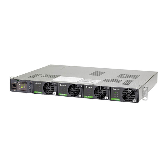
Vertiv NetSure-48 VDC Installation And User Manual
Bulk output rectifier system
Hide thumbs
Also See for NetSure-48 VDC:
- Installation instructions manual (98 pages) ,
- Installation manual (22 pages)

Related Manuals for Vertiv NetSure-48 VDC


Summary of Contents for Vertiv NetSure-48 VDC
- Page 1 NetSure™ -48 VDC Bulk Output Rectifier System Installation and User Manual Specification Number: 58870530036 Model Number: PSS4840-3/19C...
- Page 2 Vertiv™ NetSure™ -48 VDC Bulk Output Rectifier System Installation and User Manual The information contained in this document is subject to change without notice and may not be suitable for all applications. While every precaution has been taken to ensure the accuracy and completeness of this document, Vertiv assumes no responsibility and disclaims all liability for damages resulting from use of this information or for any errors or omissions.
-
Page 3: Table Of Contents
Vertiv™ NetSure™ -48 VDC Bulk Output Rectifier System Installation and User Manual TABLE OF CONTENTS Admonishments Used in this Document ..........................v Important Safety Instructions ..............................vi Safety Admonishments Definitions ............................................vi Safety and Regulatory Statements ............................................vi Déclarations de Sécurité et de Réglementation ......................................vi 1 Customer Documentation Package ..........................1... - Page 4 Vertiv™ NetSure™ -48 VDC Bulk Output Rectifier System Installation and User Manual 10 Operating Procedures ............................... 26 10.1 Controller and Rectifier ................................................26 10.2 Local Controls and Indicators ............................................26 11 Maintenance ..................................26 11.1 System Maintenance Procedures ..........................................26 11.2 Adding a Rectifier ..................................................26 12 Troubleshooting and Repair ............................27...
-
Page 5: Admonishments Used In This Document
Vertiv™ NetSure™ -48 VDC Bulk Output Rectifier System Installation and User Manual Admonishments Used in this Document will likely DANGER! Warns of a hazard the reader be exposed to that will result in death or serious injury if not avoided. (ANSI, OSHA) -
Page 6: Important Safety Instructions
Vertiv™ NetSure™ -48 VDC Bulk Output Rectifier System Installation and User Manual Important Safety Instructions Safety Admonishments Definitions Definitions of the safety admonishments used in this document are listed under “Admonishments Used in this Document” on page v. Safety and Regulatory Statements Refer to Section 4154 (provided with your customer documentation) for Safety and Regulatory Statements. -
Page 7: Customer Documentation Package
Vertiv™ NetSure™ -48 VDC Bulk Output Rectifier System Installation and User Manual 1 Customer Documentation Package This document provides Installation and User Instructions for Vertiv™ NetSure™ -48 VDC bulk output rectifier system Model PSS4840 3/19C, Spec. No. 58870530036. The complete Customer Documentation Package consists of…... -
Page 8: Specifications
Vertiv™ NetSure™ -48 VDC Bulk Output Rectifier System Installation and User Manual Rectifier Modules The system contains rectifier modules, which provide load power, battery float current, and battery recharge current during normal operating conditions. Refer to the Rectifier Instructions (UM1R482000e3) for more information. -
Page 9: Compliance Information
Vertiv™ NetSure™ -48 VDC Bulk Output Rectifier System Installation and User Manual • This product is intended for installation in network telecommunication facilities (CO, vault, hut, or other environmentally controlled electronic equipment enclosure). • This product is intended to be connected to the common bonding network in a network telecommunication facility (CO, vault, hut, or other environmentally controlled electronic equipment enclosure). - Page 10 Vertiv™ NetSure™ -48 VDC Bulk Output Rectifier System Installation and User Manual Figure 3.1: Dimensions and Weight 15.80 12.60 Top View 1.25 1.72 17.65 Left Side View Right Side View 18.30 Notes: 19.00 1. All dimensions are in inches, 22.30 unless otherwise specified.
-
Page 11: Accessory Descriptions
Vertiv™ NetSure™ -48 VDC Bulk Output Rectifier System Installation and User Manual 4 Accessory Descriptions Order the following by part number / spec. number as required. 4.1 Mounting Adapter Plates 23” Mounting Bracket Adapter Plates, P/N 563148 • Attaches to the 19” standard mounting brackets to allow 23” mounting. - Page 12 Vertiv™ NetSure™ -48 VDC Bulk Output Rectifier System Installation and User Manual Rectifier AC Input Cable Assembly, P/N 553202 • One (1) 12’ long, 8 AWG, AC input cable assembly that is terminated on one end with a Molex plug which mates with the AC input receptacle on the system, and un-terminated on the remaining end.
- Page 13 Vertiv™ NetSure™ -48 VDC Bulk Output Rectifier System Installation and User Manual Rectifier AC Input Line Cord, P/N 559842 • One (1) 6’ long, 8/3 AWG, AC input line cord that is terminated on one end with a Molex plug (wires molded 180°...
-
Page 14: Controller
Vertiv™ NetSure™ -48 VDC Bulk Output Rectifier System Installation and User Manual Rectifier AC Input Line Cord, P/N 548196 • One (1) 6’ long, 12/3 AWG, AC input line cord terminated on one end with a Molex plug which mates with the AC input receptacle on the system, and terminated on the remaining end with a IEC320 C20 plug. -
Page 15: Lugs
Vertiv™ NetSure™ -48 VDC Bulk Output Rectifier System Installation and User Manual provide this UIN number, along with the configuration number, when ordering so that the new controller will match that of the original controller shipped with the system. The user manual provided with the controller provides instructions for replacing and programming the controller. -
Page 16: Installation Acceptance Checklist
Vertiv™ NetSure™ -48 VDC Bulk Output Rectifier System Installation and User Manual 5 Installation Acceptance Checklist Provided in this section is an Installation Acceptance Checklist. This checklist helps ensure proper installation and initial operation of the system. As the procedures presented in this document are completed, check the appropriate box on this list. If the procedure is not required to be performed for your installation site, also check the box in this list to indicate that the procedure was read. -
Page 17: Making Electrical Connections
Vertiv™ NetSure™ -48 VDC Bulk Output Rectifier System Installation and User Manual Procedure For 23” mounting, attached the 23” mounting bracket adapter plates to the standard 19” mounting brackets. Position the system in the relay rack or cabinet equipment rack. -
Page 18: Frame Grounding Connection
Vertiv™ NetSure™ -48 VDC Bulk Output Rectifier System Installation and User Manual 7.3 Frame Grounding Connection For grounding requirements, refer to the current edition of the American National Standards Institute (ANSI) approved National Fire Protection Association's (NFPA) National Electrical Code (NEC), applicable local codes, and your specific site requirements. -
Page 19: Rectifier Nominal 120 Vac / 208 Vac / 240 Vac Input And Ac Input Equipment Grounding Connections
Vertiv™ NetSure™ -48 VDC Bulk Output Rectifier System Installation and User Manual WARNING! The intra-building port(s) of the equipment or subassembly is suitable for connection to intra-building or unexposed wiring or cabling only. The intra-building port(s) of the equipment or subassembly MUST NOT be metallically connected to the interfaces that connect to the OSP or its wiring. - Page 20 Vertiv™ NetSure™ -48 VDC Bulk Output Rectifier System Installation and User Manual Procedure AC input connections are made using the AC input cable assemblies or line cords ordered with the system. These are connected to the plug-in Molex connectors located on the rear of the shelf. Connect the other end of the AC input cable assemblies or line cords to a properly wired AC outlet or distribution box.
- Page 21 Vertiv™ NetSure™ -48 VDC Bulk Output Rectifier System Installation and User Manual Figure 7.3 AC Input Connections Rear Rectifier Rectifier #3 and #4 #1 and #2 AC input connections are made using the supplied AC input cable assemblies Rectifiers are numbered left to or line cords connected here.
-
Page 22: 48 Vdc Output Connections
Vertiv™ NetSure™ -48 VDC Bulk Output Rectifier System Installation and User Manual 7.6 -48 VDC Output Connections ALERT! Check for correct polarity before making connections. DC output leads are connected to the output busbars located on the back of the system as shown in Figure 7.4. These busbars provide studs for installation of customer-provided two-hole lugs. -
Page 23: Installing Rectifier Modules
Vertiv™ NetSure™ -48 VDC Bulk Output Rectifier System Installation and User Manual 8 Installing Rectifier Modules Refer to the rectifier instruction manual UM1R2000e3 for a rectifier installation procedure. 9 Initially Starting, Configuring, and Checking System Operation ALERT! Performing various steps in the following procedures may cause a service interruption and/or result in the extension of alarms. -
Page 24: Verifying And Setting The Ncu Controller As Required For Your Application
ENT key on the NCU Controller. After the NCU is powered on, the display shows the “Vertiv” screen. The controller is initializing. When initialization is complete, the language screen appears. Press the up or down arrow key to select the desired language. - Page 25 Vertiv™ NetSure™ -48 VDC Bulk Output Rectifier System Installation and User Manual NOTE! When setting total rectifier current limit, the set point to each unit is the total set point divided by the number of units. For example, if the system contains five rectifiers and the current limit is set to 150 amps then each rectifier has a current limit set point of 30 amps.
- Page 26 Vertiv™ NetSure™ -48 VDC Bulk Output Rectifier System Installation and User Manual To Change a Parameter: Press the UP and DOWN keys to move up and down the list of parameters. Press ENT to select the parameter. Press the UP and DOWN keys to change the parameter.
- Page 27 Vertiv™ NetSure™ -48 VDC Bulk Output Rectifier System Installation and User Manual Configuring the NCU Identification of Rectifiers and Assigning which Input Feed is Connected to the Rectifiers When rectifiers are all installed prior to applying power and starting the system, the order in which the NCU identifies the rectifiers is by serial number (lowest serial number is Rect 1, next lowest is Rect 2, etc.).
- Page 28 Vertiv™ NetSure™ -48 VDC Bulk Output Rectifier System Installation and User Manual NOTE! A “Rect Group All Rect No Response” alarm may activate briefly. Requirement: NCU “Critical/Major” alarm indicator goes from red to off. Requirement: Press ESC repeatedly to return to the Main screen. NCU displays “No Alarm”.
- Page 29 Vertiv™ NetSure™ -48 VDC Bulk Output Rectifier System Installation and User Manual Requirement: All external alarms deactivate. Checking System Over Voltage Alarm 1 and Over Voltage Alarm 2 Verify system is operating and no alarms are present. Verify the NCU displays the Main Menu. If not, press ESC repeatedly to return to the Main Menu.
- Page 30 Vertiv™ NetSure™ -48 VDC Bulk Output Rectifier System Installation and User Manual Requirement: NCU “Critical/Major” alarm indicator goes from red to off. Requirement: Press ESC repeatedly to return to the Main screen. NCU displays “No Alarm”. Requirement: All external alarms deactivate.
-
Page 31: Checking System Status
Vertiv™ NetSure™ -48 VDC Bulk Output Rectifier System Installation and User Manual NOTE! Low Voltage 2 alarm will retire. The audible alarm will be silenced in the next step. Use the UP or DOWN keys to scroll up to “Under Voltage 1”. -
Page 32: Final Steps
Vertiv™ NetSure™ -48 VDC Bulk Output Rectifier System Installation and User Manual 9.7 Final Steps Procedure If any controller configuration settings were changed, refer to the NCU Instructions (UM1M830BNA) and save a copy of the configuration file. This file can be used to restore the controller settings, if required, at a later date. - Page 33 Vertiv™ NetSure™ -48 VDC Bulk Output Rectifier System Installation and User Manual 12 Troubleshooting and Repair 12.1 Contact Information Refer to Section 4154 (provided with your customer documentation) for support contact information. 12.2 Controller and Rectifier For troubleshooting and repair instructions on these units, refer to the following documents.
- Page 34 Vertiv™ NetSure™ -48 VDC Bulk Output Rectifier System Installation and User Manual Refer to the NCU Controller Instructions (UM1M830BNA) for a procedure. Clearing a Rectifier Communications Fail Alarm after Removing a Rectifier If a rectifier module is removed from the system, a rectifier communications failure alarm is generated. If the rectifier module will not be replaced, the alarm should be cleared.
- Page 35 Vertiv™ NetSure™ -48 VDC Bulk Output Rectifier System Installation and User Manual Connect with Vertiv on Social Media https://www.facebook.com/vertivI https://www.instagram.com/vertiv/ https://www.linkedin.com/company/vertiv/ https://www.twitter.com/vertiv/ Proprietary and Confidential © 2022 Vertiv Group Corp.
- Page 36 Vertiv.com | Vertiv Headquarters, 1050 Dearborn Drive, Columbus, OH, 43085, USA © 2022 Vertiv Group Corp. All rights reserved. Vertiv™ and the Vertiv logo are trademarks or registered trademarks of Vertiv Group Corp. All other names and logos referred to are trade names, trademarks or registered trademarks of their respective owners. While every precaution has been taken to ensure accuracy and completeness here, Vertiv Group Corp.
Need help?
Do you have a question about the NetSure-48 VDC and is the answer not in the manual?
Questions and answers