Table of Contents
Advertisement
Quick Links
Advertisement
Table of Contents

Related Manuals for MSI E7210 MasterX-FA2R


Summary of Contents for MSI E7210 MasterX-FA2R
- Page 1 E7210 MasterX Series MS-9156 ATX Server Board G52-S9156X2...
-
Page 2: Fcc-A Radio Frequency Interference Statement
Manual Rev: 1.1 Release Date: April 2004 FCC-A Radio Frequency Interference Statement This equipment has been tested and found to comply with the limits for a class A digital device, pursuant to part 15 of the FCC rules. These limits are designed to provide reasonable protection against harmful interference when the equip- ment is operated in a commercial environment. -
Page 3: Copyright Notice
Alternatively, please try the following help resources for further guidance. Visit the MSI website for FAQ, technical guide, BIOS updates, driver updates, and other information: http://www.msi.com.tw/ Contact our technical staff at: support@msi.com.tw... -
Page 4: Safety Instructions
Safety Instructions Always read the safety instructions carefully. Keep this User’s Manual for future reference. Keep this equipment away from humidity. Lay this equipment on a reliable flat surface before setting it up. The openings on the enclosure are for air convection hence protects the equipment from overheating. -
Page 5: Table Of Contents
Safety Instructions ... v Chapter 1. Getting Started ... 1-1 Mainboard Specifications ... 1-2 Mainboard Layout ... 1-6 MSI Special Features ... 1-9 PC Alert™ III ... 1-9 Chapter 2. Hardware Setup ... 2-1 Quick Components Guide ... 2-2 Central Processing Unit: CPU ... 2-5 CPU Installation Procedures for Socket 604 ... - Page 6 Connectors ... 2-16 IDE Connectors: IDE1, IDE2 ... 2-17 Serial ATA RAID 0, 1 Connectors: SATA1, SATA2 ... 2-18 SATA RAID 0, 1, 10 Connectors: J10, J11, J12, J13 (Optional) ... 2-19 LAN LED Connectors: JACT1, JACT2 ... 2-20 Front Panel Connector: JFP1 ... 2-20 Silicon Image SATA LED Connector: JS_LED ...
- Page 7 Standard CMOS Features ... 3-6 Advanced BIOS Features ... 3-8 Advanced Chipset Features ... 3-14 Integrated Peripherals ... 3-16 Power Management Setup ... 3-21 PC Health Status ... 3-23 Frequency/Voltage Control ... 3-24 Load Fail-Safe/Optimized Defaults ... 3-25 Set Supervisor/User Password ... 3-26 Appendix A: SCSI BIOS Setup (Optional) ...
- Page 8 4. Installing SuSE Linux 8.0 or 8.1 ... B-7 Installing Adaptec Storage Manager – Browser Edition ... B-8 1. Overview ... B-8 2. Supported Browsers ... B-8 3. Typical, Custom, and Compact Installations ... B-9 4. Installing Adaptec Storage Manager on Windows ... B-10 5.
-
Page 9: Chapter 1. Getting Started
Chapter 1. Getting Started Getting Started Thank you for choosing the E7210 MasterX Series (MS- 9156 v1.X/v3.X) ATX server boards. The E7210 MasterX Series are superior computer mainboards based on Intel Hance Rapids chipsets for optimal system efficiency. Designed to fit the advanced Intel package, the E7210 MasterX Series provide a solution for front- end and general purpose server/workstation in the entry-level and mid-range market segment. -
Page 10: Mainboard Specifications
MS-9156 ATX Server Board Mainboard Specifications Target Segment Target in the entry-level and mid-range, front-end and general purpose server market segments The second-generation of microprocessors using the Intel microarchitecture Supports Single/Dual Intel Feature L2 Cache L3 Cache Data Bus Transfer Rate... - Page 11 - Ultra ATA/100 Bus Master IDE interface supported by Intel ICH (with 1 IDE connector onboard/can connect up to 2 Ultra ATA drives) E7210 MasterX-FA2R: - Serial ATA RAID interface supported by Intel SATA connectors onboard/can connect up to 2 Serial ATA drives)
- Page 12 PC2001 system design compliant Dimension Form Factor: 12” x 10.16” Mounting 17 mounting holes in total, including CPU fan mounting holes MSI Reminds You... Enabling the functionality of Hyper-Threading Technology for your computer system requires ALL of the following platform Components: ®...
- Page 13 - Integrated TMDS transmitter with support for Digital Flat Panel (DFP) monitors - Onboard 8MB Video SDRAM MSI Reminds You... Please refer to Table 1 for 2D modes supporting both CRT and LCD. The table specifies the minimum memory requirements for various display resolutions, refresh rates and color depths.
-
Page 14: Mainboard Layout
PCI 1 PCI 2 SCSI 1 E7210 MasterX-FS (MS-9156 v1.X) Server Board - SCSI interface supported by Adaptec AIC-7901 Ultra-320 SCSI controller - Serial ATA RAID interface supported by Intel SATA connectors onboard/can connect up to 2 Serial ATA drives) -
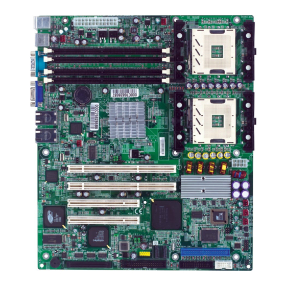
Page 15: Getting Started
PCI 1 PCI 2 CO M2 JFDD E7210 MasterX-FA2R (MS-9156 v3.X) Server Board - Serial ATA RAID interface supported by Intel SATA connectors onboard/can connect up to 2 Serial ATA drives) - Ultra ATA/100 Bus Master IDE interface supported by Intel... - Page 16 Sil 3114 CO M2 JFDD E7210 MasterX-FA6R (MS-9156 v3.X) Server Board - Serial ATA RAID interface supported by Intel con Image SiI 3114 PCI to four-port Serial ATA host controller (with 6 SATA connectors onboard/can connect up to 6 Serial ATA drives)
-
Page 17: Msi Special Features
MSI Special Features PC Alert™ III The PC Alert III is a utility you can find in the CD-ROM disk. The utility is just like your PC doctor that can de- tect the following PC hardware status during real time operation: monitor CPU &... -
Page 18: Chapter 2. Hardware Setup
Chapter 2. Hardware Setup Hardware Setup This chapter provides you with the information about hard- ware setup procedures. While doing the installation, be careful in holding the components and follow the installation procedures. For some components, if you install in the wrong orientation, the components will not work properly. -
Page 19: Quick Components Guide
JUSB1, p.2-21 J9, p.2-25 SCSI1, p.2-22 E7210 MasterX-FS (MS-9156 v1.X) Server Board - SCSI interface supported by Adaptec AIC-7901 Ultra-320 SCSI controller - Serial ATA RAID interface supported by Intel SATA connectors onboard/can connect up to 2 Serial ATA drives) - Page 20 J9, p.2-25 COM2, p.2-23 JFDD, p.2-16 E7210 MasterX-FA2R (MS-9156 v3.X) Server Board - Serial ATA RAID interface supported by Intel SATA connectors onboard/can connect up to 2 Serial ATA drives) - Ultra ATA/100 Bus Master IDE interface supported by Intel...
- Page 21 COM2, p.2-23 JFDD, p.2-16 E7210 MasterX-FA6R (MS-9156 v3.X) Server Board - Serial ATA RAID interface supported by Intel con Image SiI 3114 PCI to four-port Serial ATA host controller (with 6 SATA connectors onboard/can connect up to 6 Serial ATA drives)
-
Page 22: Central Processing Unit: Cpu
Heat Sink and cooling fan, contact your dealer to purchase and install them before turning on the computer. MSI Reminds You... Overheating will seriously damage the CPU and system, always make sure the cooling fan can work properly to protect the CPU from overheating. -
Page 23: Cpu Installation Procedures For Socket 604
MS-9156 ATX Server Board CPU Installation Procedures for Socket 604 1. Please turn off the power and unplug the power cord before installing the CPU. 2. Pull the lever sideways away from the socket. Make sure to raise the lever up to a 170- degree angle. -
Page 24: Installing The Retention Module
Installing the Retention Module MSI Reminds You... Mainboard photos shown in this section are for demonstration of the cooler installation for Socket 604 CPUs only. The ap- pearance of your mainboard may differ depending on the model you purchase. Hardware Setup 1. -
Page 25: Installing The Non-Intel Cpu Cooler
MS-9156 ATX Server Board Installing the Non-Intel CPU Cooler 1. Take out your CPU. Look for the gold arrow on the CPU. The gold arrow should point towards the lever pivot. Note that the CPU can only fit in the correct orientation. - Page 26 MSI Reminds You... Overheating Overheating will seriously damage the CPU and system, al- ways make sure the cooling fan can work properly to protect the CPU from overheating. Replacing the CPU While replacing the CPU, always turn off the ATX power sup- ply or unplug the power supply’s power cord from grounded...
-
Page 27: Installing The Intel Cpu Cooler
MS-9156 ATX Server Board Installing the Intel CPU Cooler 2-10 1. Install the Intel PWT-U cooler set in accordance with instructions described in its accompanying user’s guide. 2. We suggest that you install the PWT-U cooler in a 5U tower... -
Page 28: Removing The Retention Module
Removing the Retention Module Hardware Setup 1. Locate the retention module and clips on the mainboard. 2. Use a flat-headed screw driver to push one side of the clip off the hook. 3. Flip over the mainboard and use the screw driver to push the white push pin off the hole. -
Page 29: Memory
DDR DIMM slots (DIMM 1~4). Memory Speed/CPU FSB Support Matrix FSB400 FSB533 MSI Reminds You... If DDR266 memory is running with FSB400 CPU, memory fre- quency will drop from DDR266 to DDR200. Memory Population Rules The mainboard supports both single- & dual-channel modes. Install at least one DIMM module on the slots. -
Page 30: Installing Ddr Modules
2. Insert the DIMM memory module vertically into the DIMM slot. Then push it in until the golden finger on the memory module is deeply in- serted in the socket. MSI Reminds You... You can barely see the golden finger if the module is properly inserted in the socket. -
Page 31: Power Supply
This connector provides 12V power output to the CPU. POWER1 POWER1 Pin Definition SIGNAL +3.3V +3.3V PWR OK 5VSB +12V +12V +3.3V MSI Reminds You... Power supply of 300watt (and up) is highly recommended for system stability. 2-14 Power Supply POWER2 SIGNAL +3.3V -12V POWER2 Pin Definition PS-ON#... -
Page 32: Back Panel
Mouse Keyboard COM 1 Mouse/Keyboard Connector Pin5 Mouse/KBD Clock Pin6 NC Pin4 VCC Pin3 GND Pin1 Pin2 NC Mouse/KBD DATA Serial Port 1 2 3 4 5 6 7 8 9 VGA Port Back Panel USB Ports SIGNAL RJ-45 LAN Jack Activity Indicator SOUT Gigabit LAN Pin Definition... -
Page 33: Floppy Disk Drive Connector: Jfdd
CPU fan control. SENSOR +12V CPUFAN1/2 MSI Reminds You... Always consult the vendors for proper CPU cooling fans. 2-16 Connectors SENSOR +12V... -
Page 34: Ide Connectors: Ide1, Ide2
CD-ROM, 120MB Floppy (reserved for future BIOS) and other devices. The E7210 MasterX-FA2R & E7210 MasterX-FA6R offers two IDE con- nectors onboard for connection of up to four hard disk drives, CD-ROM, 120MB Floppy (reserved for future BIOS) and other devices. -
Page 35: Serial Ata Raid 0, 1 Connectors: Sata1, Sata2
150 MB/s and are fully compliant with Serial ATA 1.0 specifications. SATA1 SATA2 Optional Serial ATA cable MSI Reminds You... Please do not fold the Serial ATA cable into 90-degree angle. Otherwise, the loss of data may occur during transmission. 2-18 ®... - Page 36 For more information on Serial ATA RAID 0, 1, 10, please refer to (Silicon Image SiI 3114) Serial ATA RAID 0, 1, 10 Quick User’s Guide. Optional Serial ATA cable MSI Reminds You... Please do not fold the Serial ATA cable into 90-degree angle. Otherwise, the loss of data may occur during transmission.
-
Page 37: Lan Led Connectors: Jact1, Jact2
MS-9156 ATX Server Board LAN LED Connectors: JACT1, JACT2 The LAN LED connectors are used to connect to LAN LEDs, which show the activity of the LAN. JACT1 is for JLAN 1 jack and the JACT2 is for JLAN2 jack. Both JLAN1 & JLAN2 jacks are located on the back panel. -
Page 38: Silicon Image Sata Led Connector: Js_Led
Silicon Image SATA LED Connector: JS_LED This connector is used to connect LEDs for showing the activities of SiI 3114 Serial ATA devices. JS_LED Front USB Connector: JUSB1 The mainboard provides one USB 2.0 pin header JUSB1 (optional USB 2. 0 bracket available) that is compliant with Intel USB 2.0 technology increases data transfer rate up to a maximum throughput of 480Mbps, which is 40 times faster than USB 1.1, and is ideal for connecting... -
Page 39: Ultra320 Scsi Connector: Scsi 1 (Optional)
Pin Definition J10/JSCSI SIGNAL VCC5 SCSI LED HDD LED VCC5 MSI Reminds You... SCSI LED connects to JFP1 HDD LED (storage LED) pins. The J10/JSCSI is used to con- nect SCSI card LED signal. 2-22 68-Pin Ultra320 SCSI Connector Description... -
Page 40: System Status Led Header: Fault_Led
System Status LED Header: FAULT_LED Connect an LED to this header and the LED will lighten when the CPU, system, or power fan shuts down. 5-pin I C Bus Connector: IPMB The mainboard provides one I2C (also known as I users to connect to System Management Bus (SMBus) interface. -
Page 41: Parallel Port Header: Cn11
MS-9156 ATX Server Board Parallel Port Header: CN11 The mainboard provides a 25-pin header for connection to an optional parallel port bracket. The parallel port is a standard printer port that supports Enhanced Parallel Port (EPP) and Extended Capabilities Parallel Port (ECP) mode. -
Page 42: Jumpers
JBAT (Clear CMOS Jumper ) to clear data. Follow the instructions below to clear the data: JBAT MSI Reminds You... You can clear CMOS by shorting 2-3 pin while the system is off. Then return to 1-2 pin position. Avoid clearing the CMOS while the system is on;... -
Page 43: Pci-X Device Jumper: J1
MS-9156 ATX Server Board PCI-X Device Jumper: J1 This jumper specifies the type of devices installed on the PCI-X slots. PCI-X Speed Jumper: J2 The jumper is used to set the speed of the 64-bit PCI-X buses. 82541 LAN Control Jumper: J3 This jumper is used to enable/disable the onboard LAN function. -
Page 44: System Configure Jumper: J6
BIOS Flash Jumper: J7 This jumper is used to protect the BIOS boot block from virus infection. When locked, the BIOS boot block cannot be accessed, making BIOS update impossible. When BIOS update is intended, remove the jumper cap to disable BIOS flash protection. -
Page 45: Slots
MS-9156 ATX Server Board The motherboard provides two 32-bit Master PCI slots and two 64-bit PCI-X slots. 64-bit PCI-X Slots (for 32-bit long cards, 64-bit short cards, & 64-bit long cards) 32-bit PCI Slots (for 32-bit short cards only) PCI (Peripheral Component Interconnect) Slots The PCI slots allow you to insert the expansion cards to meet your needs. - Page 46 PCI-32 IRQ Routing (for ICH-HR) PCI Device INT A PCI Slot 1 PIRQ#A PCI Slot 2 PIRQ#B 82541GI LAN PIRQ#H 82547GI LAN PIRQ#F PIRQ#G PCI-64 IRQ Routing PCI Device INT A PCIX-64 Slot1 PX_IRQ#0 PCIX-64 Slot2 PX_IRQ#1 AIC-7901 SCSI PX_IRQ#2 Hardware Setup INT B INT C...
-
Page 47: Chapter 3. Bios Setup
Chapter 3. BIOS Setup BIOS Setup This chapter provides information on the BIOS Setup pro- gram and allows you to configure the system for optimum use. You may need to run the Setup program when: An error message appears on the screen during the system booting up, and requests you to run SETUP. -
Page 48: Entering Setup
MS-9156 ATX Server Board Power on the computer and the system will start POST (Power On Self Test) process. When the message below appears on the screen, press <DEL> key to enter Setup. Press DEL to enter SETUP If the message disappears before you respond and you still wish to enter Setup, restart the system by turning it OFF and On or pressing the RESET button. -
Page 49: Getting Help
Press <Esc> to exit the Help screen. MSI Reminds You... The items under each BIOS category described in this chapter are under continuous update for better system performance. -
Page 50: The Main Menu
MS-9156 ATX Server Board The Main Menu Once you enter Phoenix-Award BIOS CMOS Setup Utility, the Main Menu will appear on the screen. The Main Menu displays eleven configurable functions and two exit choices. Use arrow keys to move among the items and press <Enter>... - Page 51 BIOS Setup PC Health Status This entry shows your PC health status. Frequency/Voltage Control Use this menu to specify your settings for frequency/voltage control. Load Fail-Safe Defaults Use this menu to load the BIOS default values for minimal but stable system performance.
-
Page 52: Standard Cmos Features
MS-9156 ATX Server Board Standard CMOS Features The items inside Standard CMOS Features menu are divided into 10 categories. Each category includes none, one or more setup items. Use the arrow keys to highlight the item you want to modify and use the <PgUp> or <PgDn>... - Page 53 your hard disk drive type is not matched or listed, you can use Manual to define your own drive type manually. If you select Manual, related information is asked to be entered to the follow- ing items. Enter the information directly from the keyboard. This information should be provided in the documentation from your hard disk vendor or the system manufacturer.
-
Page 54: Advanced Bios Features
MS-9156 ATX Server Board Advanced BIOS Features Hard Disk Boot Priority This setting determines the boot priority of the installed hard disks. Virus Warning The item is to set the Virus Warning feature for IDE Hard Disk boot sector protection. If the function is enabled and any attempt to write data into this area is made, BIOS will display a warning message on screen and beep. - Page 55 Setting options: [Enabled], [Disabled]. MSI Reminds You... Enabling the functionality of Hyper-Threading Technology for your computer system requires ALL of the following platform Components: ®...
- Page 56 [CDROM] [ZIP100] [LAN] [Disabled] MSI Reminds You... Available settings for “First/Second/Third Boot Device” vary de- pending on the bootable devices you have installed. For example, if you did not install a floppy drive, the setting “Floppy” does not show up.
- Page 57 BIOS Setup rupt Controller). Due to compliance with PC2001 design guide, the system is able to run in APIC mode. Enabling APIC mode will expand available IRQ re- sources for the system. Settings: [Enabled] and [Disabled]. MPS Version Control For OS This field allows you to select which MPS (Multi-Processor Specification) version to be used for the operating system.
- Page 58 MS-9156 ATX Server Board DMI Event Log This setting disables/enables the BIOS to log DMI (Desktop Management Interface) events. Setting options: [Disabled], [Enabled]. Clear All DMI Event Log When this setting is set to [Yes], the DMI event log will be cleared at next POST stage.
- Page 59 Thermal Management This feature allows you to specify the thermal monitoring system. Settings are: [Thermal Monitoring 1 on die throttling] [Thermal Monitoring 2 Ratio & VID transition] TM2 Bus Ratio (hidden for Prescott processor) It represents the frequency (bus ratio) of the throttled performance state that will be initiated when the on die sensor goes from cool to hot.
-
Page 60: Advanced Chipset Features
MS-9156 ATX Server Board Advanced Chipset Features MSI Reminds You... Change these settings only if you are familiar with the chipset. DRAM Timing Selectable Selects whether DRAM timing is controlled by the SPD (Serial Presence Detect) EEPROM on the DRAM module. Setting to [By SPD] enables DRAM timing to be determined automatically by BIOS based on the configurations on the SPD. - Page 61 BIOS Setup refreshed. Fast speed offers faster performance while slow speed offers more stable performance. DRAM RAS# Precharge This item controls the number of cycles for Row Address Strobe (RAS) to be allowed to precharge. If insufficient time is allowed for the RAS to accumulate its charge before DRAM refresh, refresh may be incomplete and DRAM may fail to retain data.
-
Page 62: Integrated Peripherals
MS-9156 ATX Server Board Integrated Peripherals OnChip IDE Device Press <Enter> to enter the following sub-menu screen. IDE HDD Block Mode This allows your hard disk controller to use the fast block mode to transfer data to and from the hard disk drive. Block mode is also called block transfer, multiple commands or multiple sector read/write. - Page 63 BIOS Setup IDE DMA Transfer Access Setting to [Enabled] will open DMA bus master and execute DMA action in DOS, which will make the data transferring faster. Settings: [Disabled], [Enabled]. On-Chip Primary/Secondary PCI IDE The integrated peripheral controller contains an IDE interface with support for two IDE channels.
- Page 64 MS-9156 ATX Server Board => Compatible Mode with Serial ATA Port 0 set to Primary Slave 3. [Secondary Master] => Compatible Mode with Serial ATA Port 0 set to Secondary Master 4. [Secondary Slave] => Compatible Mode with Serial ATA Port 0 set to Secondary Slave 5.
- Page 65 USB Keyboard/Mouse Support Set to [Enabled] if your need to use a USB-interfaced keyboard/mouse in the operating system that does not support or have any USB driver installed, such as DOS and SCO Unix. CSA LAN (Giga-LAN) The field determines whether the onboard Giga-bit LAN controller is activated.
- Page 66 MS-9156 ATX Server Board Onboard Parallel Port This specifies the I/O port address and IRQ of the onboard parallel port. Settings: [378/IRQ7], [278/IRQ5], [3BC/IRQ7], [Disabled]. Parallel Port Mode This item selects the operating mode for the parallel port: [SPP], [EPP], [ECP], [ECP+EPP].
-
Page 67: Power Management Setup
Power Management Setup MSI Reminds You... S3-related functions described in this section are available only when your BIOS supports S3 sleep mode. ACPI Function This item is to activate the ACPI (Advanced Configuration and Power Man- agement Interface) function. If your operating system is ACPI-aware, such as Windows 98SE/2000/ME, select [Enabled]. - Page 68 The field specifies the time for Resume by Alarm. Format is <hour> <minute><second>. MSI Reminds You... If you have changed this setting, you must let the system boot up until it enters the operating system, before this function will work.
-
Page 69: Pc Health Status
BIOS Setup PC Health Status This setup screen shows the status of your CPU, fan, overall system status,.. etc. Monitor function is available only if there is hardware monitor- ing mechanism onboard. Case Open Warning The field enables or disables the feature of recording the chassis intrusion status and issuing a warning message if the chassis is once opened. -
Page 70: Frequency/Voltage Control
MS-9156 ATX Server Board Frequency/Voltage Control Use this menu to specify your settings for frequency/voltage control. Auto Detect DIMM/PCI Clk This item is used to auto detect the DIMM/PCI slots. When set to Enabled, the system will remove (turn off) clocks from empty DIMM/PCI slots to mini- mize the electromagnetic interference (EMI). -
Page 71: Load Fail-Safe/Optimized Defaults
Load Fail-Safe/Optimized Defaults The two options on the main menu allow users to restore all of the BIOS settings to the default Fail-Safe or Optimized values. The Optimized Defaults are the default values set by the mainboard manufacturer specifically for op- timal performance of the mainboard. -
Page 72: Set Supervisor/User Password
FEATURES menu. If the Security Option is set to System, the password is required both at boot and at entry to Setup. If set to Setup, password prompt only occurs when you try to enter Setup. MSI Reminds You... About Supervisor Password & User Password: Supervisor password:... -
Page 73: Appendix A: Scsi Bios Setup (Optional)
Appendix A: SCSI BIOS Setup (Optional) This chapter provides information on the Small Computer System Interface (SCSI) BIOS setup utility and allows you to configure the SCSI subsystem for optimum use. You may need to run the SCSI BIOS setup utility when: You want to change the default SCSI controller settings for customized features. -
Page 74: Entering Scsi Bios
MS-9156 ATX Server Board Entering SCSI BIOS Power on the computer and the system will start POST (Power On Self Test) process. When the message below appears on the screen, press <Ctrl> + <A> keys simultaneously to enter SCSI BIOS utility. - Page 75 AIC-7901 at slot 07, 03:07:00 Would you like to configure the SCSI controller, or run the SCSI Disk Utilities? Select the option and press <Enter>. Configure/View SCSI Controller Settings Configure/View SCSI Controller Settings Use this option for SCSI controller configurations. SCSI Disk Utilities Use this option to manage the attached SCSI device.
-
Page 76: Configure/View Scsi Controller Settings
MS-9156 ATX Server Board Configure/View SCSI Controller Settings There are 8 items in the “Configure/View SCSI Controller Settings” screen. These items display or allow you to change the SCSI controller’s settings. Use the arrow keys to highlight the item and then press <Enter> to select the value you want in each item or enter each item’s sub-menu screen. -
Page 77: Additional Options
SCSI Controller Termination In order to have the SCSI bus function properly and reliably, termination at the ends of the SCSI bus is necessary. Proper termination can ensure signal on the SCSI bus will not reflect and cause data loss or errors. Settings options: [Enabled], [Disabled]. - Page 78 MS-9156 ATX Server Board SCSI Device ID Sync Transfer Rate (MB/Sec) ... 320 320 320 320 320 320 320 320 Packetized... Yes Yes Yes Yes Yes Yes Yes Yes QAS... Yes Yes Yes Yes Yes Yes Yes Yes Initiate Wide Negotiation ... Yes Yes Yes Yes Yes Yes Yes Yes Enable Disconnection ...
- Page 79 SCSI device to disconnect during an I/O transfer operation. The discon- nection ability frees the SCSI bus to allow other I/O processes and thus optimizes the SCSI bus performance. Setting options: [Yes], [No]. Send Start Unit Command When set to Yes, the SCSI controller sends the Start Unit command to the specified SCSI device during bootup.
- Page 80 MS-9156 ATX Server Board Display <Ctrl><A> Message During BIOS Initialization When enabled, the message “Press <Ctrl><A> for SCSISelect(TM) Util- ity” appears on the screen during bootup. If disabled, the message does not show up, but you can still press <Ctrl> + <A> key combination to enter the SCSI BIOS utility.
-
Page 81: Bios Information
under the El Torito specification. If booting from a hard disk or other device, make sure no bootable CD-ROM is inserted or disable this option. BIOS Information Interrupt (IRQ) Channel Displays the IRQ line assigned to the SCSI channel. I/O Port Address Displays the I/O port address assigned to the SCSI channel. -
Page 82: Disk Utilities
MS-9156 ATX Server Board Select SCSI Disk and press <Enter> SCSI ID#0: SCSI ID#1: SCSI ID#2: SCSI ID#3: SCSI ID#4: SCSI ID#5: SCSI ID#6: SCSI ID#7: SCSI ID#8: SCSI ID#9: SCSI ID#10: SCSI ID#11: SCSI ID#12: SCSI ID#13: SCSI ID#14:... -
Page 83: Appendix B: Adaptec Sata Raid Utility For Intel Ich-Hr (Optional)
1. Supports 150 MB/s transfers with CRC error checking 2. Data handling optimizations including tagged command queuing, elevator seek and packet chain command MSI Reminds You... All the information/volumes listed in your system might differ from the illustrations in this appendix. -
Page 84: Introduction
MS-9156 ATX Server Board 1. Overview Adaptec Embedded Serial ATA RAID with HostRAID tionality to the Serial ATA I/O controller by supporting RAID levels 0 and 1. HostRAID adds entry level RAID support to the Serial ATA I/O controller. With HostRAID, you can add reliable performance and full data protection. -
Page 85: Storage Management Software Overview
Adaptec SATA RAID Utility for Intel ICH-HR 5. Storage Management Software Overview Adaptec Embedded Serial ATA RAID includes the following software tools to manage your storage subsystem: Adaptec Storage Manager – Browser Edition—Browser-based stor- age management software that provides all of the creation, management, and data logging needed to manage arrays. -
Page 86: Installing The Driver
3, insert the Windows setup CD and restart the system. 5. Press F6 when prompted to install a third-party driver. MSI Reminds You... When F6 is active, a prompt appears at the bottom of the screen. Press F6 immediately — you only have 5 seconds. If you miss your chance, restart this Windows installation to complete it correctly. -
Page 87: Installing The Driver In An Existing Windows System
Adaptec SATA RAID Utility for Intel ICH-HR 2. Installing the Driver in an Existing Windows System In this scenario, you are installing a driver in a system that already has a Windows operating system. To install the driver: 1. Create a driver disk by following the instructions from the Web site or the product CD. -
Page 88: Installing Red Hat Linux 7.3
MS-9156 ATX Server Board 3. Installing Red Hat Linux 7.3 or 8.0 Installing the Red Hat Driver in a New Linux System In this scenario, you are installing the driver in a new Linux system. To install the driver: 1. Obtain a driver disk from either the Web site or the product CD. -
Page 89: Installing Suse Linux 8.0
Adaptec SATA RAID Utility for Intel ICH-HR 4. Installing SuSE Linux 8.0 or 8.1 Installing the Driver in a New Linux System In this scenario, you are installing the driver in a new Linux system. To install the driver: 1. Obtain a driver disk from either the Web site or the product CD. 2. -
Page 90: Installing Adaptec Storage Manager - Browser Edition
MS-9156 ATX Server Board Installing Adaptec Storage Manager – Browser Edition 1. Overview This chapter discusses the installation procedure for installing Adaptec Storage Manager – Browser Edition to enable remote and local management of arrays. 2. Supported Browsers To run Adaptec Storage Manager – Browser Edition, your computer must have a Web browser supporting JavaScript and cookies only. -
Page 91: Typical, Custom, And Compact Installations
Not included in a Typical installation. Compact — Installs only the components required on a remotely man- aged system. See Managed System Components, above. MSI Reminds You... When you perform a Typical or Compact installation, components needed for communication and remote management are installed... -
Page 92: Installing Adaptec Storage Manager On Windows
MS-9156 ATX Server Board 4. Installing Adaptec Storage Manager on Windows MSI Reminds You... When installing on a FAT 32 file system, the folder being installed is automatically hidden. To install Adaptec Storage Manager – Browser Edition: 1. Verify that a supported browser is installed. See Supported Browsers for details. - Page 93 ´ Active Scripting ´ Allow per session cookies (not stored) MSI Reminds You... In Internet Explorer 6.0 there is no security setting for cookies. Cookie configuration was removed from the Privacy tab. There is no setting for blocking Intranet cookies.
- Page 94 2. Select Use a proxy server for your LAN > Advanced. 3. In the Exceptions section, type the managed system’s IP address. Configuring Netscape Navigator for Local Management MSI Reminds You... These instructions apply specifically to version 7 and may differ in later versions.
-
Page 95: Installing Adaptec Storage Manager On Linux
Adaptec SATA RAID Utility for Intel ICH-HR 5. Installing Adaptec Storage Manager on Linux MSI Reminds You... When performing this installation, keep in mind that Linux is case sensitive. To install Adaptec Storage Manager on a Linux computer and configure the desired Internet browser: 1. -
Page 96: Using Adaptec Storage Manager - Browser Edition
MSI Reminds You... Your controller may not support all of the features described. In most cases if a feature is not supported by your controller the feature does not appear in the interface. -
Page 97: Architecture Overview
Adaptec SATA RAID Utility for Intel ICH-HR 2. Architecture Overview A locally managed system requires all of these components: A supported Web browser, which should already be installed on the system. The Adaptec Web service which supplies content displayed on the Web browser. -
Page 98: Logging In
When connection to the remote sys- tem is established, the System Login screen appears. MSI Reminds You... If you are using a proxy server to access the Internet, you must bypass the proxy server to access the Adaptec Storage Manager Web server. -
Page 99: Installing A Security Certificate
Adaptec SATA RAID Utility for Intel ICH-HR 4. Installing a Security Certificate If you chose not to install a security certificate when you installed Adaptec Storage Manager – Browser Edition, you must install the certificate when you run the application for the first time. To create the certificate: 1. -
Page 100: The Basics
6. The Basics An example of a typical Adaptec Storage Manager – Browser Edition screen is shown below. MSI Reminds You... Depending on your operating system, browser, and color scheme you may notice some differences between this illustration and your screen. - Page 101 Adaptec SATA RAID Utility for Intel ICH-HR Beneath the controller information are Physical Devices and Logical De- vices views that show connected devices and existing arrays on this controller. Controller information and device views are repeated for each additional Adaptec RAID controller in the system. Select the controller by clicking anywhere on the controller information.
- Page 102 MS-9156 ATX Server Board the other two buttons. The default display is the Text Description View, but in the condensed view used when Adaptec Storage Manager is loaded, the display is the same in all three modes. If you change the display mode by selecting one of the other view buttons, a yellow arrow flashes to the left of any devices where the condensed display prevents omits information.
- Page 103 The main area of the Logical Devices view is used to display the arrays on this controller. It defaults to a condensed view of top-level arrays. MSI Reminds You... The Options button allows you to display second-level arrays if your controller supports them.
- Page 104 Selecting any of these three buttons displays a new window with additional information and options specific to that array. MSI Reminds You... For Windows Server 2003 only—to see animated icons on Adaptec Storage Manager - logical devices, go to Internet Explorer Prop- erties/Advanced/Multimedia, and check Play animations in Web Pages option.
-
Page 105: Adaptec Raid Configuration Utility
Adaptec SATA RAID Utility for Intel ICH-HR Adaptec RAID Configuration Utility The Adaptec RAID Configuration (ARC) utility is an embedded BIOS utility that includes: Array Configuration Utility (ACU)—Used to create, configure, and manage arrays. Disk Utilities—Used to format or verify disks. To run ARC, press Ctrl+A when prompted by the following message during the system startup: Press <Ctrl><A>... -
Page 106: Using The Array Configuration Utility
5. Press Esc to return to the previous menu. Deleting Arrays MSI Reminds You... Back up the data on an array before you delete it. Otherwise, all data on the array is lost. Deleted arrays cannot be restored. - Page 107 5. Press Enter when both disks for the new array are selected. The Array Properties menu displays. Assigning Array Properties MSI Reminds You... Once the array is created and its properties are assigned, you cannot change the array properties using the ACU. Instead, use Adaptec Storage Manager - Browser Edition.
- Page 108 MS-9156 ATX Server Board 4. Create RAID via allows you to select between the different creation methods for RAID 0 and RAID 1. The following table gives examples of when each is appropriate. Notes: Before adding a new drive to an array, back up any data contained on the new drive.
- Page 109 Adaptec SATA RAID Utility for Intel ICH-HR MSI Reminds You... Do not interrupt the creation of a RAID 0 using the Migrate option. If you do, there is no way to restart, and no way to recover the data that was on the source drive.
-
Page 110: Using The Disk Utilities
Serial ATA drives are low-level formatted at the factory and do not need to be low-level formatted again. MSI Reminds You... Formatting destroys all data on the drive. Be sure to back up your data before performing this operation. -
Page 111: Glossary
Adaptec SATA RAID Utility for Intel ICH-HR Glossary activity See task. Array Configuration Utility. An application used to create, configure, and man- age arrays from the controller’s BIOS or MS-DOS. array A logical disk created from available space and made up of one or more seg- ments on one or more physical disks. - Page 112 MS-9156 ATX Server Board build Background initialization of a redundant array. The array is accessible throughout. RAID 1 copies the contents of the primary drive to a secondary drive. See also clear. See channel. cache Fast-access memory on the controller that serves as intermediate storage for data that is read from, or written to, drives.
- Page 113 Adaptec SATA RAID Utility for Intel ICH-HR tolerant array to which it is explicitly assigned. degraded A redundant (for example, a RAID 1) array in which one or more members have failed. The data is intact but redundancy has been compromised. Any further failure would cause the array to fail and result in data loss.
- Page 114 MS-9156 ATX Server Board The RAID signature on the disk allows the RAID controller to identify whether or not the disk was initialized on the controller it is currently connected to. hard disk drive Basic unit of nonvolatile, nonremovable, magnetic storage media. See also disk.
- Page 115 Adaptec SATA RAID Utility for Intel ICH-HR mirrored array/mirroring See RAID 1. monitoring Process of receiving, displaying, and logging system events. offline array Array that can no longer be accessed. optimal The state of an array when it is fully operational. For redundant arrays, the entire array is protected.
- Page 116 MS-9156 ATX Server Board on different disks. RAID 0 distributes data evenly across its respective drives in equal-sized sections called stripes. RAID 0 arrays are not redundant. RAID 1 Single-level array consisting of two equal segments residing on two different drives.
- Page 117 Adaptec SATA RAID Utility for Intel ICH-HR spanned volume A simple volume that spans two or more drives. stripe Contiguous set of data distributed across all the disks in an array. A striped array distributes data evenly across all members in equalized sections called stripes.
Need help?
Do you have a question about the E7210 MasterX-FA2R and is the answer not in the manual?
Questions and answers