Table of Contents
Advertisement
Quick Links
Advertisement
Table of Contents

Subscribe to Our Youtube Channel
Related Manuals for MSI E7520 Master2-S2M


Summary of Contents for MSI E7520 Master2-S2M
- Page 1 E7520 Master2 Series MS-9136 SSI Server Board English Version G52-S9136X2...
-
Page 2: Copyright Notice
If a problem arises with your system and no solution can be obtained from the user’s manual, please contact your place of purchase or local distributor. Alternatively, please try the following help resources for further guidance. Visit the MSI website for FAQ, technical guide, BIOS updates, driver updates, and other information: faq/esc_faq_list.php Contact our technical staff at: support@msi.com.tw... -
Page 3: Safety Instructions
Safety Instructions Always read the safety instructions carefully. Keep this User’s Manual for future reference. Keep this equipment away from humidity. Lay this equipment on a reliable flat surface before setting it up. The openings on the enclosure are for air convection hence protects the equip- ment from overheating. -
Page 4: Fcc-A Radio Frequency Interference Statement
FCC-A Radio Frequency Interference Statement This equipment has been tested and found to comply with the limits for a class A digital device, pursuant to part 15 of the FCC rules. These limits are designed to provide reasonable protection against harmful interference when the equipment is operated in a commercial environment. -
Page 5: Weee (Waste Electrical And Electronic Equipment) Statement
WEEE (Waste Electrical and Electronic Equipment) Statement... -
Page 8: Table Of Contents
WEEE (Waste Electrical and Electronic Equipment) Statement ... v Chapter 1. Getting Started ... 1-1 Mainboard Specifications ... 1-2 Mainboard Layout ... 1-5 MSI Special Features ... 1-6 PC Alert™ III ... 1-6 Chapter 2. Hardware Setup ... 2-1 Quick Components Guide ... 2-2 Central Processing Unit: CPU ... - Page 9 Serial Port Connector: COM 2 ... 2-16 Jumpers ... 2-17 Clear CMOS Jumper: JBAT1 ... 2-17 BIOS Boot Block Protect Jumper: J1 ... 2-18 System Configure Jumper: CN40 ... 2-18 Slots ... 2-19 PCI (Peripheral Component Interconnect) Slots ... 2-19 PCI Interrupt Request Routing ...
- Page 10 5. Storage Management Software Overview ... B-2 Installing the Driver ... B-4 1. Installing the Driver in a New W indows System ... B-4 2. Installing the Driver in an Existing W indows System ... B-5 3. Installing Red Hat Linux 7.3 or 8.0 ... B-5 4.
-
Page 11: Chapter 1. Getting Started
Chap t er 1 . Ge tting Started Getting Started Thank you for choosing the E7520 Master2 Series (MS-9136 v2.X) SSI server board. The E7520 Master2 Series are superior com- puter mainboards based on Intel chipsets for optimal system efficiency. Designed to fit the advanced ®... -
Page 12: Mainboard Specifications
Mainboard Specifications † Dual Xeon (FSB 800MHz) processors in the 604-pin package † 1MB L2 Cache † 6.4GB/s Trans Rate (For more information on compatible components, please visit http://www.msi.com. tw/program/products/server/svr/pro_svr_qvl.php) Chipset † Intel ® Lindenhurst (E7520) MCH (Memory Controller Hub) †... -
Page 13: Getting Started
† SSI EEB 3.0 Form Factor: 12.0 x 13.0 inch M ounting † 17 mounting holes in total, including CPU fan mounting holes MSI Reminds You... Enabling the functionality of Hyper-Threading Technology for your computer system requires ALL of the following platform Components: ®... - Page 14 Video † Integrated ATI Radeon™ 7000 graphics controller - Onboard 16MB Video SDRAM MSI Reminds You... Please refer to Table 1 for 2D modes supporting both CRT and LCD. The table specifies the minimum memory requirements for various display resolutions, refresh rates and color depths.
-
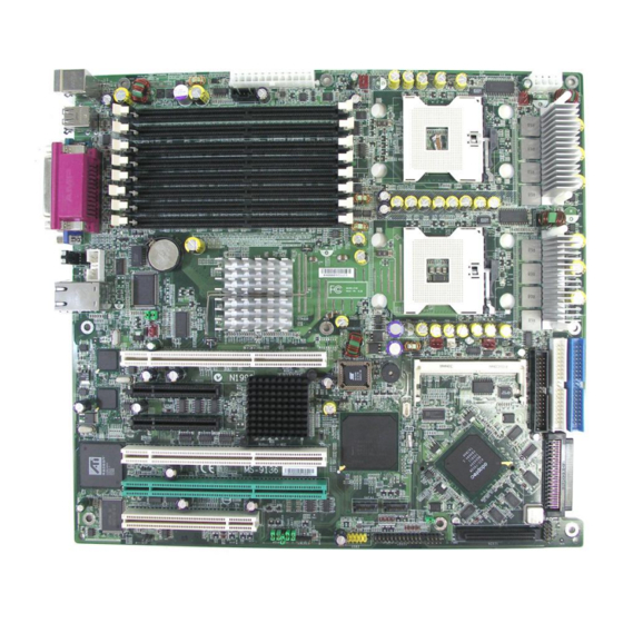
Page 15: Mainboard Layout
Gi gab it LAN PCI 5 I ntel 82 541 Gi gab it LAN PCI 4 PCI 3 RADEON PCI 2 PCI 1 JCI 1 MS-9136 v2.X SSI Server Board JPWR1 CP U1 FAN3 DIMM8 DIMM7 DIMM6 DIMM5 DI MM4 DIMM3 DIMM2... -
Page 16: Msi Special Features
MS-9136 SSI Server Board MSI Special Features PC Alert™ III The PC Alert III is a utility you can find in the CD-ROM disk. The utility is just like your PC doctor that can detect the following PC hardware status during real time operation: ö... -
Page 17: Chapter 2. Hardware Setup
Chapter 2. Hardware Setup Hardware Setup This chapter provides you with the information about hard- ware setup procedures. W hile doing the installation, be careful in holding the components and follow the installation procedures. For some components, if you install in the wrong orientation, the compo- nents will not work properly. -
Page 18: Quick Components Guide
MS-9136 SSI Server Board DIMM1~8, p.2-5 Back Panel I/O, p.2-9 COM2, p.2-16 FAN5, p.2-10 PCI Slots, p.2-19 JCI1, p.2-10 Quick Components Guide CN14, p.2-15 FAN3, p.2-10 JPWR1, p.2-8 J1, p.2-18 SATA1/2, p.2-12 USB2, p.2-13 CN40, p.2-18 JSCSI1, p.2-14 JBAT1, p.2-17 JPWR2, p.2-8... -
Page 19: Central Processing Unit: Cpu
Heat Sink and cooling fan, contact your dealer to purchase and install them before turning on the computer. MSI Reminds You... Overheating will seriously damage the CPU and system, always make sure the cooling fan can work properly to protect the CPU from overheating. -
Page 20: Cpu Installation Procedures For Socket 604
MS-9136 SSI Server Board CPU Installation Procedures for Socket 604 1. Please turn off the power and unplug the power cord before installing the CPU. 2. Pull the lever s ideways away from the socket. Make sure to raise the lever up to a 170-de- gree angle. -
Page 21: Memory
The mainboard provides 8 slots for 240-pin DDR-II DIMM modules. You can install DDR-II 400 SDRAM modules on the DDR-II DIMM slots (DIMM 1~8). Memory Bus Features u Support for direct connect of two DDR channel interfaces, DDR-II 400 technology. u Stacked or unstacked DIMM support for registered DDR-II 400 technology(up to four single-ranked or two stacked DIMMs per channel). -
Page 22: Memory Population Rules
MS-9136 SSI Server Board Memory Population Rules The mainboard supports dual-channel mode. You can install either single- or double-sided modules to meet your own needs. In dual-channel mode, make sure that you install memory modules of the same type and density on DDR DIMMs “in pairs”... -
Page 23: Installing Ddr-Ii Modules
2. Insert the DIMM memory module vertically into the DIMM slot. Then push it in until the golden finger on the memory module is deeply inserted in the socket. MSI Reminds You... You can barely see the golden finger if the module is properly inserted in the socket. -
Page 24: Power Supply
+3.3V +3.3V PWR OK 5VSB +12V +12V +3.3V MSI Reminds You... 1. Power supplies of 300watt (and up) are highly recommended for sys- tem stability. 2. Please refer to the Intel/AMD websites for recommended power supplies. Power Supply JPWR2 SIGNAL +3.3V... -
Page 25: Back Panel
M o us e Keyboard COM 1 M ouse/Keyboard Connector Pin5 Mouse/KBD Clock Pin6 NC Pin4 VCC Pin3 GND Pin1 Pin2 NC Mouse/KBD DATA Serial Port 1 2 3 4 5 6 7 8 9 VGA Port Back Panel Parallel USB Ports SIGNAL RJ-45 LAN Jack... -
Page 26: Connectors
System Hardware Monitor chipset onboard, you must use a specially designed fan with speed sensor to take advantage of the CPU fan control. +12V Sensor FAN1/3 MSI Reminds You... Always consult the vendors for proper CPU cooling fans. 2-10 Connectors JCI1... -
Page 27: Ata100 Hard Disk Connectors: Ide1 & Ide2
IDE2 (Secondary IDE Connector) IDE2 can also connect a Master and a Slave drive. MSI Reminds You... If you install two hard disks on cable, you must configure the second drive to Slave mode by setting its jumper. Refer to the hard disk docu- mentation supplied by hard disk vendors for jumper setting instructions. -
Page 28: Serial Ata Raid 0, 1 Connectors: Sata1, Sata2
ATA data rates of 150 MB/s and are fully compliant with Serial ATA 1.0 specifications. SATA1 SATA2 Optional Serial ATA cable MSI Reminds You... Please do not fold the Serial ATA cable into 90-degree angle. Otherwise, data loss may occur during transmission. 2-12 ®... -
Page 29: Front Usb Connector: Usb2
Front USB Connector: USB2 The mainboard provides one USB 2.0 pin header USB2 (optional USB 2.0 bracket available) that is compliant with Intel technology increases data transfer rate up to a maximum throughput of 480Mbps, which is 40 times faster than USB 1.1, and is ideal for connecting high-speed USB interface peripherals such as USB HDD, digital cameras, MP3 players, printers, modems and the like. -
Page 30: Ultra320 Scsi Connectors: Scsi1/Scsi2 (Optional)
This connector is used to connect to a LED for showing the activity of SCSI devices attached to the SCSI connectors. SCSI1/2 Pin Definition JSCSI MSI Reminds You... SCSI LED connects to JFP1 HDD LED (storage LED) pins . The JSCSI is used to connect SCSI card LED signal. -
Page 31: Ssi 5-Pin Power Connector: Cn14
SSI 5-Pin Power Connector: CN14 This connector provides power supply for the System Management Bus (SMB). CN14 4-pin I C Bus Connector: CN28 5-pin I C Bus Connector: CN15 The mainboard provides I2C (also known as I connect to System Management Bus (SMBus) interfaces. CN15 CN28 Hardware Setup... -
Page 32: System Id Button: Cn31
MS-9136 SSI Server Board System ID Button: CN31 The CN31 system ID button is designed to facilitate the management of two or more MS-9136 systems. W hen one of the systems crashes, users may press the CN31 button on the back panel of all systems (or alternatively press the identical... -
Page 33: Jumpers
JBAT1 (Clear CMOS Jumper) to clear data. JBAT1 MSI Reminds You... You can clear CMOS by shorting 2-3 pin while the system is off. Then return to 1-2 pin position. Avoid clearing the CMOS while the system is on;... -
Page 34: Bios Boot Block Protect Jumper: J1
MS-9136 SSI Server Board BIOS Boot Block Protect Jumper: J1 This jumper is used to protect the BIOS boot block from virus infection. W hen locked, the BIOS boot block cannot be accessed, making BIOS update impossible. When BIOS update is intended, remove the jumper cap to disable BIOS flash protection. -
Page 35: Slots
PCI 4: PCI Express x8 slot PCI 1: 32-bit/33MHz PCI slot from Hance Rapids, 3.3V device only MSI Reminds You... When adding or removing expansion cards, make sure that you unplug the power supply first. Meanwhile, read the documentation for the ex-... -
Page 36: Pci Interrupt Request Routing
MS-9136 SSI Server Board PCI Interrupt Request Routing The IRQ, acronym of interrupt request line and pronounced I-R-Q, are hard- ware lines over which devices can send interrupt signals to the microprocessor. The PCI IRQ pins are typically connected to the PCI bus INT A# ~ INT D# pins as follows:... -
Page 37: So Dimm (Small Outline Dimm)
SO DIMM (Small Outline DIMM) The SO DIMM has 144 pins and supports a full 64-bit transfer. It is specifically designed for users to install MSI’s proprietary server management tool -- MS-9569 BMC (Baseboard Management Controller) card. CN39 Hardware Setup... -
Page 38: Chapter 3. Bios Setup
SETUP. You want to change the default settings for customized features. MSI Reminds You... 1. The items under each BIOS category described in this chapter are under continuous update for better system performance. -
Page 39: Entering Setup
MS-9136 SSI Server Board Power on the computer and the system will start POST (Power On Self Test) process. When the message below appears on the screen, press <F2> key to enter Setup. Press F2 to enter SETUP If the message disappears before you respond and you still wish to enter Setup, restart the system by turning it OFF and On or pressing the RESET button. -
Page 40: Getting Help
Getting Help After entering the Setup menu, the first menu you will see is the Main Menu. Main Menu The main menu lists the setup functions you can make changes to. You can use the arrow keys ( to select the item. The on-line description of the highlighted setup function is displayed at the bottom of the screen. -
Page 41: The Menu Bar
MS-9136 SSI Server Board Once you enter PhoenixBIOS Setup Utility, the Main Menu will appear on the screen. On the Main Menu screen, you will see basic BIOS settings including system time & date, and the setup categories the BIOS supplies. Use Arrow keys to move among the items and menus, and make changes to the settings. - Page 42 BIOS Setup Security Use this menu to set Supervisor and User Passwords. Boot Use this menu to specify the priority of boot devices. Exit This menu allows you to load the BIOS default values or factory default settings into the BIOS and exit the BIOS setup utility with or without changes.
-
Page 43: Main
MS-9136 SSI Server Board The items inside the Main menu are for basic system information and configuration. Each item includes none, one or more setup items. Use the Up/Down arrow keys or <Tab> to highlight the item or field you want to modify and use the <+>... - Page 44 If you select [Manual], related information is asked to be entered to the following items. Enter the information directly from the keyboard. This information should be provided in the documentation from your hard disk vendor or the system manufacturer. [Type] [Multi-Sector Transfers] [LBA Mode Control] [Transfer Mode]...
-
Page 45: System Summary
MS-9136 SSI Server Board The items inside the Main menu are for basic system information and configuration. Each item includes none, one or more setup items. Use the Up/Down arrow keys or <Tab> to highlight the item or field you want to modify and use the <+>... -
Page 46: Advanced
Items in the menu are divided into several sub-menus. Each sub-menu provides more settings. To enter the sub-menu, highligh the sub-menu you want to configure and press <Enter>. Main System Summary Setup Warning Setting items on this menu to incorrect values may cause your system to malfunction. - Page 47 MS-9136 SSI Server Board MSI Reminds You... Enabling the functionality of Hyper-Threading Technology for your computer system requires ALL of the following platform components: * CPU: * Chipset: An Intel * BIOS: * OS: For more information on Hyper-threading Technology, go to: www.intel.com/info/hyperthreading...
- Page 48 The setting specifies whether the system will be awakened from power saving modes when activity or input signal from the specified modem is detected. Options: [Enabled], [Disabled]. MSI Reminds You... You need to install a modem card supporting power on function for “Wake On Ring” function.
- Page 49 MS-9136 SSI Server Board Embedded SCSI (Optional) The sub-menu is used to configure the onboard SCSI device. SCSI Controller (Optional) Use this feature to enable or disable the onboard SCSI controller. Option ROM Scan (Optional) Use this feature to initialize device expansion ROM.
- Page 50 Interrupt It specifies the interrupt for Port A/Port B. Options: [IRQ 3], [IRQ 4]. PS/2 Mouse If your system has a PS/2 mouse port and you install a serial pointing device, select [Disabled]. Legacy USB Support Set to [Enabled] if you need to use any USB 1.1/2.0 device in the operating system that does not support or have any USB 1.1/2.0 driver installed, such as DOS and SCO Unix.
- Page 51 MS-9136 SSI Server Board DMI Event Logging Press PgUp/<+> or PgDn/<-> to view DMI event logging. Event Log Validity: Event Log Capacity: View DMI Event Log: Event Logging: ECC Event Logging: Mark DMI Events as Read: Clear All DMI Event Logs: View DMI Event Log Press [Enter] to view the contents of the DMI event log.
- Page 52 BIOS Setup BIOS Redirection Port This feature selects the serial port to use for Console Redirection. [Disabled] completely disables Console Redirection. Setting options: [Disabled], [Serial Port Baud Rate It allows you to select delay befor key repeat. Options: [300], [1200], [2400], [9600], [19.2K], [38.4K], [57.6K], [115.2K].
-
Page 53: Ipmi (Optional)
MS-9136 SSI Server Board This setup screen appears only when the MS-9569 BMC card (for Server Management) is installed on the mainboard. Press PgUp/<+> or PgDn/<-> to configure IPMI. Main System Summary IPMI Specification Version: BMC Device ID: BMC Device Version:... - Page 54 Change COM Port Setting This setting controls the COM port setting. COM Port on BMC This setting disables/enables the COM port on BMC. System Event Logging This setting disables/enables the logging of system events. Clear System Event Log Enabling this selection will force the BIOS to clear the System Event Log on the next boot.
- Page 55 MS-9136 SSI Server Board System Event Log Press <Enter> to display the System Event Log. SEL Entry Number = SEL Record ID = SEL Record Type = Timestamp = Generator Id = SEL Message Rev = Sensor Type = Sensor Number =...
-
Page 56: Security
This section lets you set security passwords to control access to the system at boot time and/or when entering the BIOS setup program. It also allows you to set virus protection at hard disk boot sector. Main System Summary Supervisor Password Is : User Password Is : Set Supervisor Password : Set User Password :... - Page 57 MS-9136 SSI Server Board Password on boot Choosing [Enabled] requires a password on boot. It requires prior setting of the supervisor password. If the supervisor password is set and this option is disabled, BIOS assumes the user is booting. Options: [Enabled], [Disabled].
-
Page 58: Boot
Use this menu to arrange and specify the priority of the devices from which the BIOS will attempt to boot the Operating System. Main System Summary CD-ROM Drive +Removable Devices +Hard Drive IBA GE Slot 0208 v1217 IBA GE Slot 0209 v1217 F1 Help Select Item Esc Exit... -
Page 59: Exit
MS-9136 SSI Server Board The following sections describe each of the options on this menu. Note that <Esc> does not exit this menu. You must select one of the items from the menu or menu bar to exit. Main System Summary... -
Page 60: Appendix A: Scsi Bios Setup (Optional)
Appendix A: SCSI BIOS Setup (Optional) This chapter provides information on the Small Computer Sys- tem Interface (SCSI) BIOS setup utility and allows you to configure the SCSI subsystem for optimum use. You may need to run the SCSI BIOS setup utility when: You want to change the default SCSI controller settings for cus- tomized features. -
Page 61: Entering Scsi Bios
MS-9136 SSI Server Board Power on the computer and the system will start POST (Power On Self Test) process. When the message below appears on the screen, press <Ctrl> + <A> keys simulta- neously to enter SCSI BIOS utility. Press <Ctrl><A> for SCSISelect(TM) Utility Control Keys Use the following keys to navigate the SCSI BIOS menu items. - Page 62 Would you like to configure the SCSI controller, or run the SCSI Disk Utilities? Select the option and press <Enter>. Configure/View SCSI Controller Settings Configure/View SCSI Controller Settings Use this option for SCSI controller configurations. SCSI Disk Utilities Use this option to manage the attached SCSI device. AIC-7902 A at slot 0A, 03:07:00 Options SCSI Disk Utilities...
-
Page 63: Configure/View Scsi Controller Settings
MS-9136 SSI Server Board Configure/View SCSI Controller Settings There are 8 items in the “Configure/View SCSI Controller Settings” screen. These items display or allow you to change the SCSI controller’s settings. Use the arrow keys to highlight the item and then press <Enter> to select the value you want in each item or enter each item’s sub-menu screen. -
Page 64: Additional Options
the SCSI bus is necessary. Proper termination can ensure signal on the SCSI bus will not reflect and cause data loss or errors. Settings options: [Enabled], [Disabled]. Boot Device Configuration Press <Enter> to enter the sub-menu screen. Boot Device Configuration Single Image Master SCSI Controller ... - Page 65 MS-9136 SSI Server Board SCSI Device ID Sync Transfer Rate (MB/Sec) ... 320 320 320 320 320 320 320 320 Packetized... Yes Yes Yes Yes Yes Yes Yes Yes QAS... Yes Yes Yes Yes Yes Yes Yes Yes Initiate Wide Negotiation ... Yes Yes Yes Yes Yes Yes Yes Yes Enable Disconnection ...
- Page 66 Send Start Unit Command When set to Yes, the SCSI controller sends the Start Unit command to the specified SCSI device during bootup. The interface powers up the SCSI device on-at-a-time during bootup, reducing the load on the computer’s power supply. Setting options: [Yes], [No].
-
Page 67: Bios Information
MS-9136 SSI Server Board POST Display Mode The field determines how much information about your SCSI controller and devices appear on the screen during bootup. For the most complete information, choose [Diagnostic]. For a faster boot, select [Silent]. Setting options: [Verbose], [Silent], [Diagnostic]. -
Page 68: Disk Utilities
Disk Utilities AIC-7902 A at slot 0A, 03:07:00 Select SCSI Disk and press <Enter> SCSI ID#0: SCSI ID#1: SCSI ID#2: SCSI ID#3: SCSI ID#4: SCSI ID#5: SCSI ID#6: SCSI ID#7: SCSI ID#8: SCSI ID#9: SCSI ID#10: SCSI ID#11: SCSI ID#12: SCSI ID#13: SCSI ID#14: SCSI ID#15:... - Page 69 MS-9136 SSI Server Board Select the SCSI device which you want to manage by highlighting the item and press <Enter>. The following dialog box appears. Select the function you want to perform. SCSI ID# 0: Firmware: Capacity: Format Disk The utility performs low-level formatting of a hard disk drive. The function might take several hours to complete.
-
Page 70: Appendix B: Adaptec Sata Raid Utility For Intel Ich-Hr
1. Supports 150 MB/s transfers with CRC error checking 2. Data handling optimizations including tagged command queuing, elevator seek and packet chain command MSI Reminds You... All the information/volumes listed in your system might differ from the illustrations in this appendix. -
Page 71: Introduction
MS-9136 SSI Server Board 1. Overview Adaptec Embedded Serial ATA RAID with HostRAID the Serial ATA I/O controller by supporting RAID levels 0 and 1. HostRAID adds entry level RAID support to the Serial ATA I/O controller. With HostRAID, you can add reliable performance and full data protection. - Page 72 Adaptec SATA RAID Utility for Intel ICH-HR Adaptec RAID Configuration (ARC) Utility—Part of the controller’s built-in BIOS code. You start ARC by pressing Ctrl+A during BIOS startup. For details, see Adaptec RAID Configuration Utility. Array Configuration Utility (ACU)—A DOS/BIOS application used to create, configure, and manage arrays.
-
Page 73: Installing The Driver
Windows setup CD and restart the system. 5. Press F6 when prompted to install a third-party driver. MSI Reminds You... When F6 is active, a prompt appears at the bottom of the screen. Press F6 immediately — you only have 5 seconds. If you miss your chance, restart this Windows installation to complete it correctly. -
Page 74: Installing The Driver In An Existing Windows System
2. Installing the Driver in an Existing Windows System In this scenario, you are installing a driver in a system that already has a Win- dows operating system. To install the driver: 1. Create a driver disk by following the instructions from the Web site or the product CD. -
Page 75: Installing Suse Linux 8.0
MS-9136 SSI Server Board 4. Installing SuSE Linux 8.0 or 8.1 Installing the Driver in a New Linux System In this scenario, you are installing the driver in a new Linux system. To install the driver: 1. Obtain a driver disk from either the Web site or the product CD. -
Page 76: Installing Adaptec Storage Manager - Browser Edition
Typical installation. Compact — Installs only the components required on a remotely managed system. See Managed System Components, above. MSI Reminds You... When you perform a Typical or Compact installation, components needed for communication and remote management are installed automatically. -
Page 77: Installing Adaptec Storage Manager On Windows
MS-9136 SSI Server Board 4. Installing Adaptec Storage Manager on Windows MSI Reminds You... When installing on a FAT 32 file system, the folder being installed is automatically hidden. To install Adaptec Storage Manager – Browser Edition: 1. Verify that a supported browser is installed. See Supported Browsers for details. - Page 78 Active Scripting Allow per session cookies (not stored) MSI Reminds You... In Internet Explorer 6.0 there is no security setting for cookies. Cookie configuration was removed from the Privacy tab. There is no setting for blocking Intranet cookies.
- Page 79 MS-9136 SSI Server Board Configuring Netscape Navigator for Local Management MSI Reminds You... These instructions apply specifically to version 7 and may differ in later versions. To configure Netscape Navigator: 1. Log in to your computer with administrator access. 2. Select Edit > Preferences.
-
Page 80: Installing Adaptec Storage Manager On Linux
5. Installing Adaptec Storage Manager on Linux MSI Reminds You... When performing this installation, keep in mind that Linux is case sensitive. To install Adaptec Storage Manager on a Linux computer and configure the de- sired Internet browser: 1. Insert the product installation CD. -
Page 81: Using Adaptec Storage Manager - Browser Edition
Once you are logged in, you will find convenient online help to guide you through the details of creating, configuring, and managing arrays. MSI Reminds You... Your controller may not support all of the features described. In most cases if a feature is not supported by your controller the feature does not appear in the interface. -
Page 82: Architecture Overview
2. Architecture Overview A locally managed system requires all of these components: A supported Web browser, which should already be installed on the system. The Adaptec Web service which supplies content displayed on the Web browser. An Adaptec-supplied storage agent. A remotely managed system requires all of these components: The remote system must contain a browser. -
Page 83: Installing A Security Certificate
6.3.14:3513/adaptec. When connection to the remote system is established, the System Login screen appears. MSI Reminds You... If you are using a proxy server to access the Internet, you must bypass the proxy server to access the Adaptec Storage Manager Web server. See Configuring Internet Browsers on Windows for details. -
Page 84: The Basics
6. The Basics An example of a typical Adaptec Storage Manager – Browser Edition screen is shown below. MSI Reminds You... Depending on your operating system, browser, and color scheme you may notice some differences between this illustration and your screen. - Page 85 MS-9136 SSI Server Board to amber, indicating that clicking any of them will display an additional window with information and options specific to this controller. Pop-Up Tool Tips If you position the cursor over a device or button a pop-up tool tip appears. For buttons, the tips contain helpful information about the function of the button, while for devices they display additional information.
- Page 86 Adaptec SATA RAID Utility for Intel ICH-HR View is the default display mode and when expanded, will show the following information about each device: Capacity of the drive Drive manufacturer and model number SCSI drive ID, or Serial ATA port number When expanded, the Full Size Capacity View button Capacity View button represent each drive as a bar.
- Page 87 The main area of the Logical Devices view is used to display the arrays on this controller. It defaults to a condensed view of top-level arrays. MSI Reminds You... The Options button allows you to display second-level arrays if your controller supports them.
-
Page 88: Adaptec Raid Configuration Utility
The physical disks associated with the array are displayed here. 5. Press Esc to return to the previous menu. Deleting Arrays MSI Reminds You... Back up the data on an array before you delete it. Otherwise, all data on the array is lost. Deleted arrays cannot be restored. - Page 89 5. Press Enter when both disks for the new array are selected. The Array Properties menu displays. Assigning Array Properties MSI Reminds You... Once the array is created and its properties are assigned, you cannot change the array properties using the ACU. Instead, use Adaptec Stor- age Manager - Browser Edition.
- Page 90 Adaptec does not recommend that you migrate or build an array on Win- dows dynamic disks (volumes), as it will result in data loss. MSI Reminds You... Do not interrupt the creation of a RAID 0 using the Migrate option. If you do, there is no way to restart, and no way to recover the data that was on the source drive.
-
Page 91: Using The Disk Utilities
Drives attached to the controller must be initialized before they can be used in an array. MSI Reminds You... Initializing a disk overwrites the partition table on the disk and makes any data on the disk inaccessible. If the drive is used in an array, you may not be able to use the array again. -
Page 92: Glossary
Adaptec SATA RAID Utility for Intel ICH-HR Glossary activity See task. Array Configuration Utility. An application used to create, configure, and manage arrays from the controller’s BIOS or MS-DOS. array A logical disk created from available space and made up of one or more segments on one or more physical disks. - Page 93 MS-9136 SSI Server Board cache Fast-access memory on the controller that serves as intermediate storage for data that is read from, or written to, drives. capacity Total usable space available in megabytes or gigabytes. channel Any path, or bus, used for the transfer of data and the control of information be- tween storage devices and a RAID controller.
- Page 94 Adaptec SATA RAID Utility for Intel ICH-HR drive LED Disk indicator LED that illuminates during read or write operations. event Notification or alert from the system, indicating that a change has occurred. event log File used to maintain information about prior controller activities or errors. event notification Process for transmitting events.
- Page 95 MS-9136 SSI Server Board initialized array An array that is ready for data reads and writes. Arrays can be initialized by build or clear. legacy disk Disk that contained a valid partition table when connected to the controller. The controller manages the disk as a legacy disk array where there is a one-to-one logical-to-physical mapping of array to disk.
- Page 96 Adaptec SATA RAID Utility for Intel ICH-HR quick init An array initialized using the Quick Init option is available immediately, with no on- going background controller activity. All data written to an array that has been quick initialized is protected. RAID Redundant Array of Independent Disks (alternative definition Redundant Array of Inexpensive Disks).
- Page 97 MS-9136 SSI Server Board single-level array Array created from one or more segments. See also volume, spanned volume, RAID 0, RAID 1. snapshot Instantaneous read-only copy of an array at a precise point in time. spanned volume A simple volume that spans two or more drives.
Need help?
Do you have a question about the E7520 Master2-S2M and is the answer not in the manual?
Questions and answers