Table of Contents
Advertisement
Advertisement
Chapters
Table of Contents

Related Manuals for MSI MS-S1311


Summary of Contents for MSI MS-S1311
- Page 1 MS-S1311 (v1.X) Server Board...
-
Page 2: Revision History
Alterna- tively, please try the following help resources for further guidance. Visit the MSI website for technical guide, BIOS updates, driver updates and other information, or contact our technical staff via http://www.msi.com/support/... -
Page 3: Safety Instructions
MS-S1311 Safety Instructions ■ Always read the safety instructions carefully. ■ Keep this User’s Manual for future reference. ■ Keep this equipment away from humidity. ■ Lay this equipment on a reliable flat surface before setting it up. ■ The openings on the enclosure are for air convection hence protects the equipment from overheating. -
Page 4: Chemical Substances Information
Chemical Substances Information In compliance with chemical substances regulations, such as the EU REACH Regulation (Regulation EC No. 1907/2006 of the European Parliament and the Council), MSI provides the information of chemical substances in products at: http://www.msi.com/html/popup/csr/evmtprtt_pcm.html Battery Information European Union: Batteries, battery packs, and accumulators should not be disposed of as unsorted household waste. -
Page 5: Ce Conformity
MSI will comply with the prod- uct take back requirements at the end of life of MSI-branded products that are... -
Page 6: Japan Jis C 0950 Material Declaration
Declaration A Japanese regulatory requirement, defined by specification JIS C 0950, man- dates that manufacturers provide material declarations for certain categories of electronic products offered for sale after July 1, 2006. http://www.msi.com/html/popup/csr/cemm_jp.html http://tw.msi.com/html/popup/csr_tw/cemm_jp.html 日本JIS C 0950材質宣言 日本工業規格JIS C 0950により、2006年7月1日以降に販売される特定分野の 電気および電子機器について、製造者による含有物質の表示が義務付けられま... -
Page 7: Vietnam Rohs
Việt Nam RoHS Kể từ ngày 01/12/2012, tất cả các sản phẩm do công ty MSI sản xuất tuân thủ Thông tư số 30/2011/TT-BCT quy định tạm thời về giới hạn hàm lượng cho phép... -
Page 8: Table Of Contents
Preface CONTENTS Copyright Notice .................... ii Trademarks ....................ii Revision History .................... ii Technical Support ..................ii Safety Instructions ..................iii Chemical Substances Information ............... iv Battery Information ..................iv CE Conformity ....................v FCC-A Radio Frequency Interference Statement ......... v WEEE Statement .................. - Page 9 MS-S1311 Server Mgmt .....................3-22 Security ....................3-24 Boot ......................3-25 Save & Exit ....................3-26 4. Drivers & Utilities.................4-1 Installation ....................4-2 Server Drivers ....................4-2 Manual .......................4-3 Download Website ..................4-3...
-
Page 11: Overview
Overview Thank you for choosing the MS-S1311 v1.X, an excellent server board from MSI. Based on the innovative Intel C612 for optimal system efficiency, the ® MS-S1311 accommodates Intel Xeon E5-2600v3/ E5-1600v3 series ® ® processor and supports 8 DDR4 slots for up to 512 GB of DDR4 RDIMM/ LRDIMM in quad-channel memory bus. -
Page 12: Motherboard Specifications
Overview Motherboard Specifications Processor ■ Single Intel Xeon E5-2600v3/ E5-1600v3 series ® ® Chipset ■ Intel C612 ® Memory Capacity ■ DIMM Quantity: - 8 x DDR4 slots ■ DIMM Type/ Speed: - DDR4 1866MHz (2 DPC)/ 2133MHz (1 DPC) RDIMM - DDR4 2133MHz (2 DPC/ 1 DPC) LRDIMM ■... - Page 13 MS-S1311 Expansion Slot ■ PCIE_1: PCIe 2.0 x8 slot (x4 signal, optional with Intel I350) ® Important Intel I350 Gigabit Ethernet controller will work only when the PCIE_1 slot is ® vacant. ■ PCIE_2: PCIe 3.0 x8 slot ■ PCIE_4: PCIe 3.0 x16 slot ■...
- Page 14 Overview Form Factor ■ ATX, 12” (304.8mm) x 9.6” (243.84mm) Mounting ■ 10 x mounting holes SKU Comparison SKUs SKU 1 SKU 2 Features Intel I350 ® Rear I/O GbE LAN ports...
-
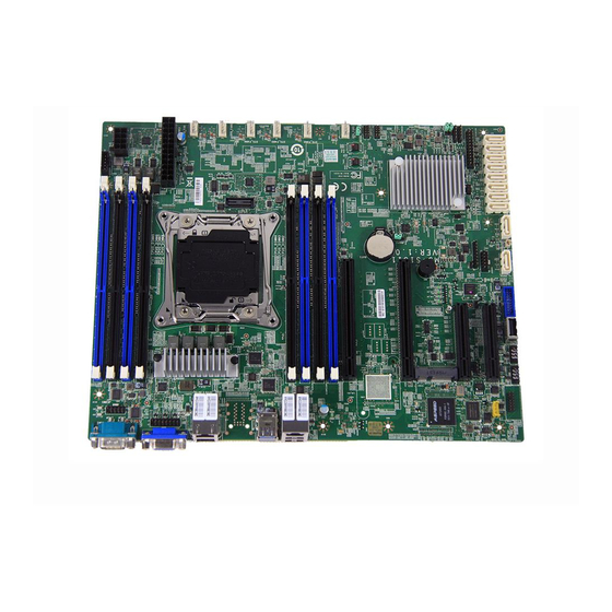
Page 15: Motherboard Layout
MS-S1311 Motherboard Layout... -
Page 17: Hardware Setup
Hardware Setup This chapter provides you with the information about hardware setup procedures. While doing the installation, be careful in holding the com- ponents and follow the installation procedures. For some components, if you install in the wrong orientation, the components will not work prop- erly. - Page 18 Hardware Setup Components Reference Guide CPU (Central Processing Unit) ............2-3 Memory ....................2-7 Storage ....................2-10 Power Supply ..................2-12 System Power Connector: JPWR3 ............2-12 CPU Power Connector: JPWR1 ...............2-12 SATA DOM Power Connector: JSDOMPWR1 .........2-12 Rear Panel I/O .................2-13 Connector ..................2-15 Fan Power Connector: CPU_FAN, SYS_FAN1 ~ SYS_FAN5 ....2-15 I2C Bus Connector: JPMBUS1 ..............2-15 IPMB Connector: J_IPMB1 ..............2-15 Front USB Connector: JUSB2, JUSB3, USB2 .........2-16...
-
Page 19: Cpu (Central Processing Unit)
MS-S1311 CPU (Central Processing Unit) Introduction to the LGA2011-3 CPU The surface of the LGA2011- 3 CPU has four alignment keys and a yellow triangle to assist in correctly lining up the CPU for mainboard placement. yellow triangle is the Pin 1 indicator. -
Page 20: Cpu & Heatsink Installation
Hardware Setup CPU & Heatsink Installation When installing a CPU, always remember to install a CPU heatsink. A CPU heatsink is necessary to prevent overheating and maintain system stability. Follow the steps below to ensure correct CPU and heatsink installation. Wrong installation can damage both the CPU and the motherboard. - Page 21 MS-S1311 5. Line up the CPU to fit the CPU socket. Be sure to hold the CPU by the base with the metal contacts facing downward. The alignment keys on the CPU will line up with the edges of the CPU socket to ensure a correct fit.
- Page 22 Hardware Setup 9. Evenly spread a thin layer of thermal paste (or thermal tape) on the top of the CPU. This will help in heat dissipation and prevent CPU overheating. 10. Locate the CPU fan connector on the mainboard. Thermal paste 11.
-
Page 23: Memory
MS-S1311 Memory Quad-Channel Mode This mode is enabled when four, or a multiple of four, memory modules are iden- tical in capacity and speed, and are placed in quad-channel slots. When two memory modules are installed, the system will operate in dual-channel mode. - Page 24 Hardware Setup • Always insert memory module into the DIMM1 slot first. • Paired memory installation for Max performance. • Populate the same DIMM type in each channel, specifically: 1. Use the same DIMM size; 2. Use the same number of ranks per DIMM. •...
-
Page 25: Installing Memory Modules
MS-S1311 Installing Memory Modules 1. The memory module has only one notch on the center and will only fit in the right orientation. 2. Insert the memory module vertically into the DIMM slot. Then push it in until the golden finger on the memory module is deeply inserted in the DIMM slot. -
Page 26: Storage
Hardware Setup Storage Storage Port Location 2-10... - Page 27 MS-S1311 Storage Support Comparison Port SATA 6 Gb/s Chip Wellsburg C612 Storage Speed Chip Wellsburg C612 Port SATA0 SATA 6 Gb/s SATA1 SATA 6 Gb/s SATA2 SATA 6 Gb/s SATA3 SATA 6 Gb/s SATA4 SATA 6 Gb/s SATA5 SATA 6 Gb/s...
-
Page 28: Power Supply
Hardware Setup Power Supply System Power Connector: JPWR3 This connector allows you to connect a power supply. To connect to the power supply, make sure the plug of the power supply is inserted in the proper orienta- tion and the pins are aligned. Then push down the power supply firmly into the connector. -
Page 29: Rear Panel I/O
MS-S1311 Rear Panel I/O RJ45 GbE SKU 1 LAN Port (for Mgmt) Serial Port VGA Port RJ45 GbE USB 3.0 USB 2.0 LAN Port Port Port RJ45 GbE SKU 2 LAN Port (for Mgmt) Serial Port VGA Port RJ45 GbE LAN Port USB 3.0... - Page 30 Hardware Setup RJ45 GbE LAN Port (for Mgmt) Network routers and switches typically require an RS-232 serial data connection to interface with the system for initial configuration. Serial data connections may also be used for diagnostics purposes, especially when a network device is mal- functioning and unreachable over the network.
-
Page 31: Connector
MS-S1311 Connector Fan Power Connector: CPU_FAN, SYS_FAN1 ~ SYS_FAN5 The fan power connectors support system cooling fan with +12V. When con- necting the wire to the connectors, always note that the red wire is the positive and should be connected to the +12V; the black wire is Ground and should be connected to GND. -
Page 32: Front Usb Connector: Jusb2, Jusb3, Usb2
Hardware Setup Front USB Connector: JUSB2, JUSB3, USB2 This connector, compliant with Intel I/O Connectivity Design Guide, is ideal for ® connecting high-speed USB interface peripherals such as USB HDD, digital cam- eras, MP3 players, printers, modems and the like. Important Note that the pins of VCC and GND must be connected correctly to avoid pos- sible damage. -
Page 33: Sgpio Header: J_Sgpio1, J_Ssgpio1
MS-S1311 SGPIO Header: J_SGPIO1, J_SSGPIO1 This connector is used to support serial-link interface for the onboard SATA con- nectors. Front Panel Header: JFP1 The front panel connector is provided for electrical connection to the front panel switches and LEDs. 2-17... -
Page 34: Chassis Intrusion Switch Header: Jci1
Hardware Setup Chassis Intrusion Switch Header: JCI1 This connector connects to the chassis intrusion switch cable. If the chassis is opened, the chassis intrusion mechanism will be activated. The system will re- cord this status and show a warning message on the screen. To clear the warn- ing, you must enter the BIOS utility and clear the record. -
Page 35: Tpm Module Header: Jtpm1
MS-S1311 TPM Module Header: JTPM1 This connector connects to a TPM (Trusted Platform Module) module (optional). Please refer to the TPM security platform manual for more details. 2-19... -
Page 36: Serial Port Header: Jcom1
Hardware Setup Serial Port Header: JCOM1 This connector is a 16550A high speed communications port that sends/receives 16 bytes FIFOs. You can attach a serial device to it. VGA Header: JVGA1 The VGA connector is provided for monitors. 2-20... -
Page 37: Jumper
MS-S1311 Jumper Clear CMOS Jumper: JBAT1 There is a CMOS RAM onboard that has a power supply from an external battery to keep the data of system configuration. With the CMOS RAM, the system can automatically boot OS every time it is turned on. If you want to clear the system configuration, set the jumper to clear data. -
Page 38: Slot
Hardware Setup Slot PCIe (Peripheral Component Interconnect Express) Slot The PCI Express slots support PCIe interface expansion cards. ■ PCIE_1: PCIe 2.0 x8 slot (x4 signal, optional with Intel I350) ® Important Intel I350 Gigabit Ethernet controller will work only when the PCIE_1 slot is ®... -
Page 39: Bios Setup
BIOS Setup This chapter provides information on the BIOS Setup program and allows users to configure the system for optimal use. Users may need to run the Setup program when: ■ An error message appears on the screen at system startup and requests users to run SETUP. -
Page 40: Entering Setup
BIOS Setup Entering Setup Power on the computer and the system will start POST (Power On Self Test) pro- cess. When the message below appears on the screen, press <DEL> or <ESC> key to enter Setup. Press <DEL> or <ESC> to enter SETUP If the message disappears before you respond and you still wish to enter Setup, restart the system by turning it OFF and On or pressing the RESET button. -
Page 41: Control Keys
MS-S1311 Control Keys ← → Select Screen ↑ ↓ Select Item Enter Select Change Option General Help Previous Values Optimized Defaults Save & Exit Exit Getting Help After entering the Setup menu, the first menu you will see is the Main Menu. -
Page 42: The Menu Bar
BIOS Setup The Menu Bar ▶ Main Use this menu for basic system configurations, such as time, date, etc. ▶ Advanced Use this menu to set up the items of special enhanced features. ▶ Intel RC Setup Use this menu to configure Intel processor and chipset features. ▶... -
Page 43: Main
MS-S1311 Main ▶ BIOS Information, Memory Information, Access Level These items show the firmware and hardware specifications of your system. Read only. ▶ System Date This setting allows you to set the system date. The date format is <Day>, <Month>... -
Page 44: Advanced
BIOS Setup Advanced ▶ Boot Feature ▶ SOL Setting This setting enables/disables the SOL setting. - Page 45 MS-S1311 ▶ Chassis Intrusion This setting enables/disables the feature of recording the chassis intrusion status and issuing a warning message if the chassis is once opened. To clear the warning message, set the field to [Reset]. The setting of the field will auto- matically return to [Enable] later.
- Page 46 BIOS Setup ▶ PCI/PCIE Configuration ▶ Maximum Payload This setting sets the maximum TLP payload size for the PCI Express devices. The unit is byte. ▶ PCI Latency Timer This item controls how long each PCI device can hold the bus before another takes over.
- Page 47 MS-S1311 ▶ Trusted Computing ▶ Security Device Support This setting enables/disables BIOS support for security device. When set to [Disable], the OS will not show security device. TCG EFI protocol and INT1A interface will not be available. ▶ Super IO Configuration...
- Page 48 BIOS Setup ▶ Serial Port 1 Configuration, Serial Port 2 Configuration ▶ Serial Port This setting enables/disables the specified serial port. ▶ Device Settings This setting shows the address & IRQ settings of the specified serial port. ▶ Change Settings This setting is used to change the address &...
- Page 49 MS-S1311 ▶ Console Redirection Console Redirection operates in host systems that do not have a monitor and keyboard attached. This setting enables/disables the operation of console re- direction. When set to [Enabled], BIOS redirects and sends all contents that should be displayed on the screen to the serial COM port for display on the terminal screen.
- Page 50 BIOS Setup ▶ Bits per second, Data Bits, Parity, Stop Bits This setting specifies the transfer rate (bits per second, data bits, parity, stop bits) of Console Redirection. ▶ Flow Control Flow control is the process of managing the rate of data transmission be- tween two nodes.
- Page 51 MS-S1311 ▶ H/W Monitor This menu shows the hardware monitor status. ▶ Voltage Status 3-13...
- Page 52 BIOS Setup ▶ Fan Status ▶ Temperature Status 3-14...
-
Page 53: Intel Rc Setup
MS-S1311 Intel RC Setup 3-15... - Page 54 BIOS Setup ▶ Processor Configuration This menu shows the processor information. ▶ Hyper-Threading (ALL) The processor uses Hyper-Threading technology to increase transaction rates and reduces end-user response times. The technology treats the two cores inside the processor as two logical processors that can execute instruc- tions simultaneously.
- Page 55 MS-S1311 ▶ Adjacent Cache Prefetch The processor has a hardware adjacent cache line prefetch mechanism that automatically fetches an extra 64-byte cache line whenever the processor requests for a 64-byte cache line. This reduces cache latency by making the next cache line immediately available if the processor requires it as well.
- Page 56 BIOS Setup ▶ IIO Configuration This menu shows the memory information. ▶ PCIE_2, PCIE_4, PCIE_6 These settings control the speeds of the specified PCIe slots. ▶ Enable IOAT Intel I/O Acceleration Technology (Intel I/OAT), a component of Intel Virtual- ization Technology for Connectivity, improves data flow across the platform to enhance system performance.
- Page 57 MS-S1311 ▶ PCH Configuration ▶ PCH sSATA Configuration ▶ Configure sSATA as This setting specifies the SATA controller mode. ▶ Aggressive Link Power Management Aggressive Link Power Management (ALPM) is a power-saving technique that helps the disk save power by setting a SATA link to the disk to a low- power setting during idle time.
- Page 58 BIOS Setup ▶ Hot Plug These settings enable/disable hot plugging of the specified SATA ports. ▶ Spin Up Device AHCI supports staggered spin-up of the specified SATA devices. ▶ PCH SATA Configuration ▶ Configure SATA as This setting specifies the SATA controller mode. ▶...
- Page 59 MS-S1311 ▶ Server ME Configuration This menu displays the ME subsystem information. 3-21...
-
Page 60: Server Mgmt
BIOS Setup Server Mgmt ▶ System Event Log Note: All values changed here do not take effect until the computer is restarted. ▶ SEL Components This setting enables/disables system event log components. ▶ Erase SEL This setting offers different options for erasing the system event logs. 3-22... - Page 61 MS-S1311 ▶ When SEL is Full This setting offers options for reactions to a full system event log. ▶ BMC Network Configuration ▶ Configuration Address Source This setting selects whether to configure LAN channel parameters statically or dynamically (DHCP). 3-23...
-
Page 62: Security
BIOS Setup Security ▶ Administrator Password Administrator Password controls access to the BIOS Setup utility. Users will be prompted for Administrator password only when they enter BIOS Setup. ▶ User Password User Password controls access to the system at boot and access to the BIOS Setup utility. -
Page 63: Boot
MS-S1311 Boot ▶ Boot Mode Select Use the setting to specify the boot mode. ▶ Fixed Boot Order Priorities, UEFI USB Key Drive BBS Priorities The items allow you to set the sequence of boot devices where BIOS attempts to load the disk operating system. -
Page 64: Save & Exit
BIOS Setup Save & Exit ▶ Save Changes and Reset Save changes to CMOS and reset the system. ▶ Discard Changes and Reset Abandon all changes and reset the system. ▶ Save Changes Save all changes and continue with the Setup Utility. ▶... -
Page 65: Drivers & Utilities
Drivers & Utilities This chapter provides information on system drivers and utilities. Important • Please note that firmware update assumes technician-level experience. • As the system firmware is under continuous update for better system performance, the illustrations in this chapter should be held for reference only. -
Page 66: Installation
The installation will auto-run, simply click the driver or utility and follow the on-screen instructions to complete the installation. Important Please visit the MSI website to get the latest drivers and BIOS for better system performance. Server Drivers This menu provides available drivers. -
Page 67: Manual
MS-S1311 Manual A user’s manual in PDF format can be acquired through this menu. Download Website Visit the MSI website for technical guides, BIOS updates, driver updates and other information.
Need help?
Do you have a question about the MS-S1311 and is the answer not in the manual?
Questions and answers