Table of Contents
Advertisement
Advertisement
Table of Contents

Related Manuals for MSI E7230 Master-FA4R


Summary of Contents for MSI E7230 Master-FA4R
- Page 1 E7230 Master Series MS-9618 (v1.X) ATX Server Board English Version G52-S9618X1...
-
Page 2: Copyright Notice
If a problem arises with your system and no solution can be obtained from the user’s manual, please contact your place of purchase or local distributor. Alternatively, please try the following help resources for further guidance. Visit the MSI website for FAQ, technical guide, BIOS updates, driver updates, and other information: faq/esc_faq_list.php Contact our technical staff at: support@msi.com.tw... -
Page 3: Safety Instructions
Safety Instructions Always read the safety instructions carefully. Keep this User’s Manual for future reference. Keep this equipment away from humidity. Lay this equipment on a reliable flat surface before setting it up. The openings on the enclosure are for air convection hence protects the equip- ment from overheating. -
Page 4: Fcc-B Radio Frequency Interference Statement
FCC-B Radio Frequency Interference Statement T h is eq uip men t h as been tested and found to c omply with the limits for a Class B digital device, pursuant to Part 15 of the FCC Rules. These limits are designed to provide reasonable protection against harmful interference in a residential installation. -
Page 5: Weee (Waste Electrical And Electronic Equipment) Statement
WEEE (Waste Electrical and Electronic Equipment) Statement... -
Page 8: Table Of Contents
W EEE (Waste Electrical and Electronic Equipment) Statement ... v Chapter 1. Getting Started ... 1-1 Mainboard Specifications ... 1-2 Mainboard Layout ... 1-4 MSI Special Features ... 1-5 PC Alert™ III ... 1-5 Chapter 2. Hardware Setup ... 2-1 Quick Components Guide ... 2-2 Central Processing Unit: CPU ... - Page 9 Front Panel Connector: JFP1 ... 2-16 Power Saving Switch Connector: JGS1 ... 2-17 LAN LED Connectors: JACT1, JACT2 ... 2-17 Fan Power Connectors: CPU_FAN1, SFAN1/2/3/4 ... 2-17 LCD Panel Connector: JLCD1 ... 2-18 Serial Port Header: COM2 ... 2-18 Front USB Connectors: JUSB1, JUSB2 ... 2-19 Jumpers ...
-
Page 10: Chapter 1. Getting Started
Cha pter 1 . Getting Started Getting Started Thank you for choosing the E7230 Master Series (MS-9618 v1.X), an excellent ATX server board from MSI. Based on the innovative Intel optimal system efficiency, the E7230 Master Series mainboard ac- commodates the latest Intel... -
Page 11: Mainboard Specifications
MS-9618 ATX Server Board Mainboard Specifications † Supports Intel ® Pentium † Supports Intel ® Hyper-Threading Technology (For more information on compatible components, please visit http://www.msi. com.tw/program/products/server/svr/pro_svr_qvl.php) Chipset † Intel ® E7230 Northbridge ® - Supports Intel Pentium 533/800/1066 MT/s... - Page 12 Onboard Peripherals † 1 floppy port supports one FDD with 360KB, 720KB, 1.2MB, 1.44MB, and 2.88MB † 1 PS/2 keyboard port † 1 PS/2 mouse port † 1 serial port & 1 serial pinheader † 1 VGA port † 1 parallel port supports SPP/EPP/ECP mode †...
-
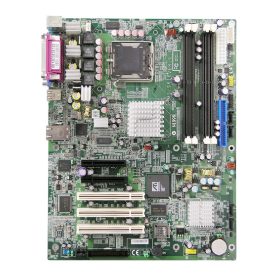
Page 13: Mainboard Layout
MS-9618 ATX Server Board Top: Mou se B otto m: K ey boar d CPU _FA N1 Top: P ara llel P ort B otto m: C OM A V GA Po rt U SB P ort s JP WR 1 PC82573V N217230C1 L AN Ja ck s... -
Page 14: Msi Special Features
MSI Special Features PC Alert™ III The PC Alert III is a utility you can find in the application CD. The utility is just like your PC doctor that can detect the following PC hard- ware status during real time operation: ö... -
Page 15: Chapter 2. Hardware Setup
Chapter 2. Hardware Setup Hardware Setup This chapter provides you with the information about hardware setup procedures. W hile doing the installation, be careful in holding the c omponents and follow the installation procedures . For s ome components, if you install in the wrong orientation, the components will not work properly. -
Page 16: Quick Components Guide
MS-9618 ATX Server Board Quick Components Guide JPW1, p.2-9 CPU_FAN1, p.2-17 I/O Ports, p.2-10 J5/J8, p.2-21 PCI Express Slots, p.2-22 JGS1, p.2-17 PCI Slots, p.2-22 FDD1, p.2-14 SFAN2/1, p.2-17 DIMM1/2/3/4, p.2-7 CPU, p.2-3 J2, p.2-21 JUSB1, p.2-19 COM2, p.2-18 JLCD1, p.2-18 ATX1, p.2-9 JUSB2, p.2-19 JACT1/2,... -
Page 17: Central Processing Unit: Cpu
If you do not have the heat sink and cooling fan, contact your dealer to purchase and install them before turning on the computer. For more information on compatible components, please visit http://www.msi.com. tw/program/products/server/svr/pro_svr_qvl.php . MSI Reminds You... -
Page 18: Cpu & Cooler Installation
MS-9618 ATX Server Board CPU & Cooler Installation W hen you are installing the CPU, make sure the CPU has a cooler attached on the top to prevent overheating. If you do not have the cooler, contact your dealer to purchase and install them before turning on the computer. Meanwhile, do not forget to apply some silicon heat transfer compound on CPU before installing the heat sink/ cooler fan for better heat dispersion. - Page 19 5. Lift the load lever up and open the load plate. 7. Visually inspect if the CPU is seated well into the socket. If not, take out the CPU with pure vertical motion and reinstall. Hardware Setup 6. After confirming the CPU direction for correct mating, put down the CPU in the socket housing frame.
- Page 20 MSI Reminds You... 1. Confirm if your CPU cooler is firmly installed before turning on your system. 2. Check the information in PC Health Status of H/W Monitor in BIOS (refer to p.3-21 for details) for the CPU temperature.
-
Page 21: Memory
DDR2 memory module in the DDR2 slot (DIMM1~DIMM4). Otherwise, you will not be able to boot up your system and your mainboard might be damaged. For more information on compatible components, please visit http://www.msi.com. tw/program/products/server/svr/pro_svr_qvl.php . Introduction to DDR2 SDRAM DDR2 is a new technology of memory module, and its speed is the top limit of current DDR technology. -
Page 22: Installing Ddr2 Modules
256MB~1GB 256MB~1GB 256MB~1GB 256MB~1GB MSI Reminds You... - Dual-channel DDR2 works ONLY in the 5 combinations listed in the table shown in the previous page. - Please select the identical memory modules to install on the dual channel, and DO NOT install three memory modules on three DIMMs, or it may cause some failure. -
Page 23: Power Supply
This connector provides 12V power output to the CPU. ATX1 JPW1 MSI Reminds You... 1. Maker sure that these two connectors are connected to adequate ATX power supplies to ensure stable operation of the mainboard. 2. Power supply of 350watts (and above) is highly recommended for system stability. -
Page 24: Back Panel
MS-9618 ATX Server Board Parallel M ou se Keyboard COM Port Mouse Connector (Green) / Keyboard Connector (Purple) The mainboard provides a standard PS/2 ® attaching a PS/2 mouse/keyboard. You can plug a PS/2 into this connector. The connector location and pin assignments are as follows: 2-10 Back Panel VGA Port... -
Page 25: Serial Port
Serial Port The mainboard offers one 9-pin male DIN connector as the serial port. The port is a 16550A high speed communication port that sends/receives 16 bytes FIFOs. You can attach a serial mouse or other serial devices directly to the connector. 1 2 3 4 5 6 7 8 9 9-Pin Male DIN Connector... -
Page 26: Usb Ports
MS-9618 ATX Server Board USB Ports The rear panel provides two UHCI (Universal Host Controller Interface) Universal Serial Bus roots for attaching USB devices such as keyboard, mouse or other USB- compatible devices. You can plug the USB device directly into the connector. LAN (RJ-45) Jacks The mainboard provides 2 standard RJ-45 jacks for connection to single Local Area Network (LAN). -
Page 27: Parallel Port Connector: Lpt1
Parallel Port Connector: LPT1 The mainboard provides a 25-pin female centronic connector as LPT. A parallel port is a standard printer port that supports Enhanced Parallel Port (EPP) and Extended Capabilities Parallel Port (ECP) mode. Pin Definition SIGNAL DESCRIPTION STROBE Strobe DATA0 Data0... -
Page 28: Connectors
IDE1 can connect a Master and a Slave drive. You must configure the second hard drive to Slave mode by setting the jumper accordingly. MSI Reminds You... If you install two hard disks on cable, you must configure the second drive to Slave mode by setting its jumper. -
Page 29: Serial Ata Connectors: Sata1~Sata4
& operation. SATA1~4 Serial ATA Cable (Optional) Connect to serial ATA ports MSI Reminds You... Please do not fold the Serial ATA cable into 90-degree angle. Otherwise, the loss of data may occur during transmission. Hardware Setup... -
Page 30: Chassis Intrusion Switch Connector: Jci1
MS-9618 ATX Server Board Chassis Intrusion Switch Connector: JCI1 This connector is connected to a 2-pin chassis switch. If the chassis is opened, the switch will be short. The system will record this status and show a warning mes- sage on the screen. To clear the warning, you must enter the BIOS utility and clear the record. -
Page 31: Power Saving Switch Connector: Jgs1
SENSOR Control CPU_FAN1 SFAN1/2 MSI Reminds You... 1. Please refer to the recommended CPU fans at Intel or consult the vendors for proper CPU cooling fan. 2. CPU_FAN1 supports Smart Fan control. You can install PC Alarm utility that will automatically control the CPU fan speed according to the actual CPU temperature. -
Page 32: Lcd Panel Connector: Jlcd1
MS-9618 ATX Server Board LCD Panel Connector: JLCD1 The connector is additionally provided for connection to a LCD panel, which shows information on the panel for you to identify the current status or mode of the con- nected system. JLCD1 Serial Port Header: COM2 The mainboard offers one 9-pin header as serial port. -
Page 33: Front Usb Connectors: Jusb1, Jusb2
USB HDD, digital cameras, MP3 players, printers, modems and the like. JUSB1 Connect to JUSB1 or JUSB2 (the USB pinheader in YELLOW color) MSI Reminds You... Note that the pins of VCC and GND must be connected correctly to avoid possible damage. JUSB2 Pin Definition... -
Page 34: Jumpers
MS-9618 ATX Server Board The motherboard provides the following jumpers for you to set the computer’s function. This section will explain how to change your motherboard’s function through the use of jumpers. Clear CMOS Jumper: JBAT1 There is a CMOS RAM on board that has a power supply from external battery to keep the data of system configuration. -
Page 35: Bios Write Protect Jumper: J2
BIOS Write Protect Jumper: J2 A "boot block" program is included as part of the system BIOS to recover the system from a situation when the BIOS code is incorrect/corrupted or needs to be updated. W hen the BIOS code is corrupted or needs to be updated, you have to at first disable the write protect function by shorting 1-2 pin of the J2 jumper. -
Page 36: Slots
MS-9618 ATX Server Board The mainboard provides: † Three 32-bit/33MHz v2.3 PCI slots (support 3.3V/5V PCI bus interface) † One PCI Express x8 slot (this PCIE_2 slot will accept x8 cards, but run at x4 speeds / PCI Express Bus specification v1.0a compliant) †... -
Page 37: Pci Interrupt Request Routing
PCI Interrupt Request Routing The IRQ, acronym of interrupt request line and pronounced I-R-Q, are hardware lines over which devices can send interrupt signals to the microprocessor. The PCI IRQ pins are typically connected to the PCI bus pins as follows: DEVICE ICH INT Pin PCI Slot 1... -
Page 38: Chapter 3. Bios Setup
SETUP. ² You want to change the default settings for customized features. MSI Reminds You... 1. The items under each BIOS category described in this chapter are under continuous update for better system performance. -
Page 39: Entering Setup
MS-9618 ATX Server Board Entering Setup Power on the computer and the system will start POST (Power On Self Test) process. W hen the message below appears on the screen, press <F1> key to enter Setup. Press F2 to enter SETUP If the message disappears before you respond and you still wish to enter Setup, restart the system by turning it OFF and On or pressing the RESET button. -
Page 40: The Menu Bar
BIOS Setup The Menu Bar Once you enter PhoenixBIOS Setup utility, the Main Menu will appear on the screen. On the Main Menu screen, you will see basic BIOS settings including system time & date, and the setup categories the BIOS supplies. Use Arrow keys to move among the items and menus, and make changes to the settings. -
Page 41: Main
MS-9618 ATX Server Board Main The items inside the Main menu are for basic system information and configuration. Each item includes none, one or more setup items. Use the Up/Down arrow keys or <Tab> to highlight the item or field you want to modify and use the <+> or <-> key to switch to the value you prefer. - Page 42 [Type] [Multi-Sector Transfers] [LBA Mode Control] [32-Bit I/O] [Tranfer Mode] [Ultra DMA Mode] Boot Features The sub-menu is used to configure system boot-up features. Floppy Check This setting causes the BIOS to search for floppy disk drives at boot time. W hen enabled, the BIOS will activate the floppy disk drives during the boot process.
- Page 43 MS-9618 ATX Server Board QuickBoot M ode Setting the item to [Enabled] allows the system to boot within 5 seconds since it will skip some check items. Available options: [Enabled], [Disabled]. Installed M emory/ Available to OS/ Used by Devices The three items show the memory status of the system.
-
Page 44: Advanced
BIOS Setup Advanced Items in the menu are divided into several sub-menus. Each sub-menu provides more settings. To enter the sub-menu, highligh the sub-menu you want to configure and press <Enter>. PCI Configuration The sub-menu is used to configure PCI settings for optimal system performance. - Page 45 MS-9618 ATX Server Board PCI Device, Slot #1 / Slot #2 / Slot #3 The sub-menu is used to configure the specified PCI device. Option ROM Scan Use this feature to initialize device expansion ROM. Enable Master W hen set to [Enabled], BIOS will activate the selected device as a PCI bus master.
- Page 46 Advanced Chipset Control The sub-menu is used to configure chipset features for optimal system performance. ECC Condition This setting specifies whether ECC Error Condition will be detected. ECC Error Handler W hen an ECC error occurs, an interrupt is generated. This setting selects the type of interrupt to report: [NMI] Non-Maskable Interrupt...
- Page 47 MS-9618 ATX Server Board MSI Reminds You... Legacy Mode: * In this mode, system BIOS just assign the traditional 14 and 15 IRQs to use for HDD. * Older OS’s that do not support switch to Native Mode (DOS, Win2K, Win98/ME...) should set SATA and PATA to Legacy Mode.
- Page 48 Please disable this item if your operating system doesn’t support HT Function, or unreliability and instability may occur. Settings: [Enabled], [Disabled]. MSI Reminds You... Enabling the functionality of Hyper-Threading Technology for your computer system requires ALL of the following platform components:...
- Page 49 MS-9618 ATX Server Board Thermal M anagement 2 This setting allows users to select between Thermal Management 1 & Thermal Management 2. Set Max Ext CPUID = 3 This setting sets the Max CPUID extended function value to 3. VT Feature This setting disables/enables the Vanderpool Technology.
- Page 50 V(VCC5), V(Vcore), V(VCC3), V(V_1P5), V(12V), V(3Vsb), CPU/ SYS Temperature, CPU Fan/ SYS Fan1/ SYS Fan2 Speed These items display the current status of all of the monitored hardware de- vices/components such as CPU voltage, temperatures and all fans’ speeds. ASF Configuration This submenu specifies the ASF configuration.
- Page 51 Press PgUp/<+> or PgDn/<-> to configure Console Redirection. The following submenu will appear. Com Port Address This feature allows you to enable/disable the Com port on the motherboard. Options: [Disabled], [On-board COM A]. Baud Rate It allows you to select delay befor key repeat. Options: [300], [1200], [2400], [9600], [19.2K], [38.4K], [57.6K], [115.2K].
- Page 52 I/O Device Configuration The sub-menu is used to configure I/O Devices for optimal system performance. Integrated Device Control Sub-Menu The sub-menu is used to configure the specified integrated device. Legacy USB Support Set to [Enabled] if your need to use any USB 1.1/2.0 device in the operating system that does not support or have any USB 1.1/2.0 driver installed, such as DOS and SCO Unix.
- Page 53 MS-9618 ATX Server Board Serial Port A/B These settings specify the base I/O port addresses of the onboard Serial Port A / B. Selecting [Auto] allows BIOS to automatically determine the correct base I/ O port address. Settings: [3F8/IRQ4], [2F8/IRQ3], [3E8/IRQ4], [2E8/IRQ3] and [Disabled].
- Page 54 DM I Event Logging Press PgUp/<+> or PgDn/<-> to view DMI event logging. View DM I Event Log Press [Enter] to view the contents of the DMI event log. Event Logging This setting disables/enables the BIOS to log DMI (Desktop Management Interface) events.
-
Page 55: Security
MS-9618 ATX Server Board Security This section lets you set security passwords to control access to the system at boot time and/or when entering the BIOS setup program. Supervisor Password Is/ User Password Is It shows the preset supervisor/user password. (read only) Set Supervisor Password Supervisor Password controls access to the BIOS Setup utility. -
Page 56: Power
Use this menu to specify your settings for Power Management. Remember that the options available depend upon the hardware installed in your system. Resume On M odem Ring Select [On] to wake up the system when an incoming call is detected on the modem. Options: [On], [Off]. -
Page 57: Boot
MS-9618 ATX Server Board Boot Use this menu to arrange and specify the priority of the devices from which the BIOS will attempt to boot the Operating System. Boot Priority Order This setting allows users to set the boot priority of the specified devices. First press <Enter>... -
Page 58: Exit
BIOS Setup Exit The following sections describe each of the options on this menu. Note that <Esc> does not exit this menu. You must select one of the items from the menu or menu bar to exit. Exit Saving Changes W hen you want to quit the Setup menu, you can select this option to save the changes and quit. -
Page 59: Appendix A: Intel Ich7R Sata Raid (Optional
RAID volumes to share the combined space of two hard drives being used in unison. MSI Reminds You... The maximum number of hard drives for RAID 0, RAID 1 or Matrix mode is 2. The maximum number of hard drives for RAID 10 mode is 4. -
Page 60: Bios Configuration
Intel RAID Option ROM. During the Power-On Self Test (POST), the following message will appear for a few seconds: MSI Reminds You... The “Driver Model”, “Serial #” and “Size” in the following example might be different from your system. - Page 61 After pressing the <Ctrl> and <I> keys simultaneously, the following window will appear: (1) Create RAID Volume Select option 1 “Create RAID Volume” and press <Enter> key. The following screen appears. Then in the Name field, specify a RAID Volume name and then press the <TAB>...
- Page 62 MS-9618 ATX Server Board In the Disk field, press <Enter> key and the following screen appears. Use <Space> key to select the disks you want to create for the RAID volume, then click <Enter> key to finish selection. Then select the strip value for the RAID array by using the “upper arrow” or “down arrow”...
- Page 63 MSI Reminds You... Since you want to create two volumes (Intel Matrix RAID Technology), this default size (maximum) needs to be reduced. Type in a new size for the first volume. As an example: if you want the first volume to span the first half of the two disks, re-type the size to be half of what is shown by default.
- Page 64 Here you can delete the RAID volume, but please be noted that all data on RAID drives will be lost. MSI Reminds You... If your system currently boots to RAID and you delete the RAID volume in the Intel RAID Option ROM, your system will become unbootable.
- Page 65 RAID structures from the drives. The following screen appears: Press <Y> key to accept the selection. MSI Reminds You... 1. You will lose all data on the RAID drives and any internal RAID structures when you perform this operation.
-
Page 66: Installing Software
† Existing Windows 2000/2003 Driver Installation 1. Insert the MSI application CD into the CD-ROM drive. 2. The CD will auto-run and the setup screen will appear. 3. Under the Driver Utility tab, click on Intel IAA RAID Edition. -
Page 67: Installation Of Intel Matrix Stroage Console
For this reason, you cannot remove or un-install this driver from the system after installation; however, you will have the ability to un-install all other non-driver components. Insert the MSI application CD and click on the Intel IAA RAID Edition to install the s of tware. Click on this item... - Page 68 MS-9618 ATX Server Board The InstallShield Wizard will begin automatically for installation showed as following: Click on the Next button to proceed the installation in the welcoming window. A-10...
- Page 69 Intel ICH7R SATA RAID The window shows the components to be installed. Click Next button to continue. After reading the license agreement in the following window, click Yes button to continue. A-11...
- Page 70 MS-9618 ATX Server Board Select the folder in which you want the program to be installed in the following window, and click Next button to start installation. Select a program folder in the following window where you want Setup to add the program icon.
- Page 71 Intel ICH7R SATA RAID The following window appears to show the Intel Application Accelerator RAID Edition Setup installation status. Once the installation is complete, the following window appears. Click Finish, and restart the system. A-13...
-
Page 72: Raid Migration Instructions
3. Install the Intel Matrix Storage Console after the operating system is installed. To create a volume from an existing disk, complete the following steps: MSI Reminds You... A Create from Existing Disk operation will delete all existing data from the added disk and the data cannot be recovered. It is critical to backup all important data on the added disk before proceeding. -
Page 73: Create Raid Volume From Existing Disk
Intel ICH7R SATA RAID Create RAID Volume from Existing Disk To create a RAID volume from an existing disk, choose Action --> Create RAID Volume from Existing Hard Drive. The Create RAID Volume from Existing Hard Drive Wizard pops up to lead you for the following procedure. - Page 74 MS-9618 ATX Server Board (1) Step 1: Configure Volume Here you can configure the new RAID volume by entering the volume name, selecting the RAID level and strip size. † RAID Volume Name: A desired RAID volume name needs to be typed in where the ‘RAID_Volume1’ text currently appears above.
- Page 75 RAID 10 (Mirrored Stripes) – A RAID 1 array of two RAID 0 arrays. † Strip Sizes: Select the desired strip size setting. As indicated, the optimal setting is 128KB. Selecting any other option may result in performance degradation. Even though 128KB is the recommended setting for most users, you should choose the strip size value which is best suited to your specific RAID usage model.
- Page 76 MS-9618 ATX Server Board (3) Select Member Hard Drive(s) Then select the member disk (the target disk) that you wish to use and then click “--->” to move it to the Selected field. Then click Next to continue. Please note that the existing data on the selected hard drive(s) will be deleted permanently.
- Page 77 (4) Specify Volume Size Specify the amount of available array space to be used by the new RAID volume. You may enter the amount in the space or use the slider to specify. It is recom- mended you use 100% of the available space for the optimized usage. For RAID 0 volume, if you do not specify 100% of the hard drive space, the rest hard drive space will be worked as RAID 1 volume, which is the new technology called Intel Matrix RAID.
- Page 78 MS-9618 ATX Server Board (6) Start Migration The migration process may take up to two hours to complete depending on the size of the disks being used and the strip size selected. A dialogue window will appear stating that the migration process may take considerable time to complete, meanwhile a popup dialogue at the taskbar will also show the migration status.
Need help?
Do you have a question about the E7230 Master-FA4R and is the answer not in the manual?
Questions and answers