Table of Contents
Advertisement
Quick Links
Advertisement
Chapters
Table of Contents

Subscribe to Our Youtube Channel
Related Manuals for MSI MS-S2381


Summary of Contents for MSI MS-S2381
- Page 1 MS-S2381 Server Board...
-
Page 2: Revision History
Preface Copyright and Trademarks Notice Copyright © Micro-Star Int’l Co., Ltd. All rights reserved. The MSI logo used is a registered trademark of Micro-Star Int’l Co., Ltd. All other marks and names men- tioned may be trademarks of their respective owners. No warranty as to accuracy or completeness is expressed or implied. -
Page 3: Safety Instructions
MS-S2381 Safety Instructions ■ Always read the safety instructions carefully. ■ Keep this User’s Manual for future reference. ■ Keep this equipment away from humidity. ■ Lay this equipment on a reliable flat surface before setting it up. ■ The openings on the enclosure are for air convection hence protects the equipment from overheating. -
Page 4: Chemical Substances Information
Chemical Substances Information In compliance with chemical substances regulations, such as the EU REACH Regulation (Regulation EC No. 1907/2006 of the European Parliament and the Council), MSI provides the information of chemical substances in products at: https://storage-asset.msi.com/html/popup/csr/evmtprtt_pcm.html Battery Information European Union: Batteries, battery packs, and accumulators should not be disposed of as unsorted household waste. -
Page 5: Ce Conformity
MS-S2381 CE Conformity Hereby, Micro-Star International CO., LTD declares that this de- vice is in compliance with the essential safety requirements and other relevant provisions set out in the European Directive. FCC-A Radio Frequency Interference Statement This equipment has been tested and found to comply with the limits for a Class A digital device, pursuant to Part 15 of the FCC Rules. -
Page 6: Table Of Contents
Preface CONTENTS Copyright and Trademarks Notice ..............ii Revision History .................... ii Technical Support ..................ii Safety Instructions ..................iii Chemical Substances Information ............... iv Battery Information ..................iv CE Conformity ....................v FCC-A Radio Frequency Interference Statement ......... v WEEE Statement ..................v . -
Page 7: Overview
Overview Thank you for choosing the MS-S2381, an excellent server board from MSI. The MS-S2381 features the latest AMD EPYC™ processor and the ® industry’s latest technologies to deliver high-performance, feature-rich server solutions for a wide array of business applications. -
Page 8: Specifications
Overview Specifications Model S2381 Form factor Dimensions 12”(W) x 9.6" (D) Processor 1 x AMD EPYC Rome/Milan (Socket SP3), upto 64C, upto 300W Memory 8 x DDR4 2400/2666/3200 MHz, RDIMM/LRDIMM slots, w/ ECC 1 x GbE RJ45 Mgmt (Realtek RTL8211E‐VB PHY) Network 2 x 10GbE RJ45 (Intel X710AT2) (1x w/ NCSI) 4 x PCIe 4.0 x 16 slots Expansion slot 3 x PCIe 4.0 x 8 slots 3 x SlimlineSAS (12x SATA 6Gb/s) Storage 2 x SlimlineSAS (PCIe 4.0 x4) for U.2 2 x M.2 M‐Key 2280/22110 (PCIe4.0 x4) 1x VGA header 1x COM header 2x USB 3.2/2.0 (header) 1x Front Panel header 1x Chassis intrusion header Internal I/O 1x IPMB header 1x PWR SMB header 1x 24pin power connector 1x 8pin power connector 1x 4pin power connector 4 x USB 3.2/2.0 2 x 10G Base‐T 1 x RJ45 Mgmt. Rear I/O 1 x VGA Port 1 x COM Port DB9 1 x UID w/ LED Security TPM 2.0 header on board Management Aspeed AST2500 IPMI2.0 with iKVM support (dual BMC design) -
Page 9: Layout
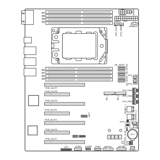
MS-S2381 Layout JPWR2 JPWR3 JPMBUS1 JSL_SATA1 SYS_FAN2 SYS_FAN1 PCIE_SLOT7 SYS_FAN5 PCIE_SLOT6 SYS_FAN4 PCIE_SLOT5 SYS_FAN3 PCIE_SLOT4 PCIE_SLOT3 BP_I2C_1 JRESET1 SOC_SMB PCIE_SLOT2 PCIE_SLOT1 BIOS_SW1 NVME_SW JCOM3 JVGA1 JCOM2 JFUSB1 JTPM1 JSGPIO1 JFP1 JIPMB1... -
Page 11: Hardware Setup
Hardware Setup This chapter provides you with the information about hardware setup procedures. While doing the installation, be careful in holding the components and follow the installation procedures. For some components, if you install in the wrong orientation, the components will not work properly. - Page 12 Hardware Setup Components Reference Guide CPU Installation ................2-3 Memory ....................2-5 Supported DIMM Configurations ..............2-5 Memory Speed Based on DIMM Population ..........2-7 Installing Memory Modules ................2-8 Storage ....................2-9 Storage Support & Speed ................2-9 Power Connectors ................2-10 Power Connectors: JPWR1, JPWR2, JPWR3 ........2-10 Rear Panel I/O .................2-12 Connectors ..................2-14 CPU Fan Power Connectors: CPU_FAN1 ..........2-14...
-
Page 13: Cpu Installation
MS-S2381 CPU Installation... - Page 14 Hardware Setup Important • Do not touch the CPU socket pins to avoid damage. • Whenever CPU is not installed, always protect your CPU socket pins with the plastic cap covered. • Please refer to the documentation in the CPU cooler package for more details about the CPU cooler installation.
-
Page 15: Memory
MS-S2381 Memory Channel H Channel G Channel F Channel E Channel A Channel B Channel C Channel D Supported DIMM Configurations... - Page 16 Hardware Setup...
-
Page 17: Memory Speed Based On Dimm Population
MS-S2381 Memory Speed Based on DIMM Population... -
Page 18: Installing Memory Modules
Hardware Setup Installing Memory Modules 1. Unlock the DIMM slot by flipping open its side clips. 2. Vertically insert the DIMM into the DIMM slot. The DIMM has an off-center notch at the bottom that will only allow it to fit one way into the DIMM slot. 3. -
Page 19: Storage
MS-S2381 Storage JPWR2 JPWR3 JPMBUS1 JSL_SATA1 SYS_FAN2 SYS_FAN1 PCIE_SLOT7 SYS_FAN5 PCIE_SLOT6 SYS_FAN4 PCIE_SLOT5 SYS_FAN3 PCIE_SLOT4 PCIE_SLOT3 BP_I2C_1 JRESET1 SOC_SMB PCIE_SLOT2 PCIE_SLOT1 BIOS_SW1 NVME_SW JCOM3 JVGA1 JCOM2 JFUSB1 JTPM1 JSGPIO1 JFP1 JIPMB1 Storage Support & Speed Storage Speed JSL_SATA1 4x SATA 6Gb/s... -
Page 20: Power Connectors
Hardware Setup Power Connectors JPWR2 JPWR3 JPMBUS1 JSL_SATA1 SYS_FAN2 SYS_FAN1 PCIE_SLOT7 SYS_FAN5 PCIE_SLOT6 SYS_FAN4 PCIE_SLOT5 SYS_FAN3 PCIE_SLOT4 PCIE_SLOT3 BP_I2C_1 JRESET1 SOC_SMB PCIE_SLOT2 PCIE_SLOT1 BIOS_SW1 NVME_SW JCOM3 JVGA1 JCOM2 JFUSB1 JTPM1 JSGPIO1 JFP1 JIPMB1 Power Connectors: JPWR1, JPWR2, JPWR3 These connectors allow you to connect a power supply. JPWR2 P12V JPWR1... - Page 21 MS-S2381 P3V3 P3V3 P3V3 -12V PS-ON# JPWR3 ATX_POK 5VSB P12V P12V P3V3 Important Make sure that all power connectors are connected to the power supply to ensure stable operation of the motherboard. 2-11...
-
Page 22: Rear Panel I/O
Hardware Setup Rear Panel I/O GbE RJ45 Port (for mgmt) COM Port UID LED VGA Port UID Button USB 3.2 Ports 10GbE RJ45 Ports COM Port The serial port is a 16550A high speed communications port that sends/receives 16 bytes FIFOs. It supports barcode scanners, barcode printers, bill printers, credit card machine, etc. - Page 23 MS-S2381 10GbE RJ45 Port The standard RJ-45 LAN jack is for connection to the Local Area Network (LAN). You can connect a network cable to it. 1GbE LED Status Description No link Link/ Activity LED Green Linked LINK/ACT SPEED Blinking...
-
Page 24: Connectors
Hardware Setup Connectors CPU Fan Power Connectors: CPU_FAN1 The fan power connector supports CPU cooling fans. System Fan Power Connectors: SYS_FAN1 ~ SYS_FAN6 The fan power connectors support system cooling fans. JPWR2 JPWR3 JPMBUS1 JSL_SATA1 SYS_FAN2 SYS_FAN1 PCIE_SLOT7 SYS_FAN5 PCIE_SLOT6 SYS_FAN4 PCIE_SLOT5 SYS_FAN3... -
Page 25: Front Panel Header: Jfp1
MS-S2381 Front Panel Header: JFP1 The front panel connector is provided for electrical connection to the front panel switches and LEDs. JPWR2 JPWR3 JPMBUS1 JSL_SATA1 SYS_FAN2 SYS_FAN1 PCIE_SLOT7 SYS_FAN5 PCIE_SLOT6 SYS_FAN4 PCIE_SLOT5 SYS_FAN3 PCIE_SLOT4 PCIE_SLOT3 BP_I2C_1 JRESET1 SOC_SMB PCIE_SLOT2 PCIE_SLOT1... -
Page 26: Chassis Intrusion Header: Jchassis1
Hardware Setup Chassis Intrusion Header: JCHASSIS1 This connector connects to the chassis intrusion switch cable. If the chassis is opened, the chassis intrusion mechanism will be activated. The system will record this status and show a warning message on the screen. To clear the warning, you must enter the BIOS utility and clear the record. -
Page 27: Pmbus Box Header: Jpmbus1
MS-S2381 PMBus Box Header: JPMBUS1 IPMB Box Header: JIPMB1 This connector is used to connect the IPMB (Intelligent Platform Management Bus). BP SMB Box Header: BP_I2C_1 These connectors, known as I2C, are provided for users to connect System Management Bus (SMBus) interface. -
Page 28: Com Port Header: Jcom2
Hardware Setup COM Port Header: JCOM2 This connector is a 16550A high speed communications port that sends/receives 16 bytes FIFOs. You can attach a serial device to it. SGPIO Box Header: JSGPIO1 This connector is provided for the General-Purpose Input/Output (GPIO) peripheral module. -
Page 29: Usb 3.2 Gen 1 Box Header: Jfusb1
MS-S2381 USB 3.2 Gen 1 Box Header: JFUSB1 This port is backward-compatible with USB 2.0 devices and supports data transfer rate up to 5 Gbit/s (SuperSpeed). JPWR2 JPWR3 JPMBUS1 JSL_SATA1 SYS_FAN2 SYS_FAN1 PCIE_SLOT7 SYS_FAN5 PCIE_SLOT6 SYS_FAN4 PCIE_SLOT5 SYS_FAN3 PCIE_SLOT4 PCIE_SLOT3... -
Page 30: Tpm Module Box Header: Jtpm1
Hardware Setup TPM Module Box Header: JTPM1 This connector connects to a TPM (Trusted Platform Module) module (optional). Please refer to the TPM security platform manual for more details. JPWR2 JPWR3 JPMBUS1 JSL_SATA1 SYS_FAN2 SYS_FAN1 PCIE_SLOT7 SYS_FAN5 PCIE_SLOT6 SYS_FAN4 PCIE_SLOT5 SYS_FAN3 PCIE_SLOT4 PCIE_SLOT3... -
Page 31: Jumper
MS-S2381 Jumper Important Avoid adjusting jumpers when the system is on; it will damage the motherboard. JPWR2 JPWR3 JPMBUS1 JSL_SATA1 SYS_FAN2 SYS_FAN1 PCIE_SLOT7 SYS_FAN5 PCIE_SLOT6 SYS_FAN4 PCIE_SLOT5 SYS_FAN3 PCIE_SLOT4 PCIE_SLOT3 BP_I2C_1 JRESET1 SOC_SMB PCIE_SLOT2 PCIE_SLOT1 BIOS_SW1 NVME_SW JCOM3 JVGA1 JCOM2... -
Page 32: Slots
Hardware Setup Slots PCIe (Peripheral Component Interconnect Express) Slot The PCI Express slots support PCIe interface expansion cards. ■ PCIE_SLOT1 x16: PCIe x8 slot, Gen4 speed ■ PCIE_SLOT2 x8: PCIe x16 slot, Gen4 speed ■ PCIE_SLOT3 x16: PCIe x8 slot, Gen4 speed ■...
Need help?
Do you have a question about the MS-S2381 and is the answer not in the manual?
Questions and answers