Table of Contents
Advertisement
Quick Links
A8027G
06/17
Copyright © 2017, Sargent Manufacturing Company, an ASSA ABLOY Group company.
All rights reserved. Reproduction in whole or in part without the express written
permission of Sargent Manufacturing Company is prohibited.
H2
Harmony Series
Mortise Lock
with iCLASS SE
Installation Instructions
Reader
®
Advertisement
Table of Contents

Related Manuals for Assa Abloy Sargent Harmony Series


Summary of Contents for Assa Abloy Sargent Harmony Series
- Page 1 SE Reader ® Installation Instructions A8027G 06/17 Copyright © 2017, Sargent Manufacturing Company, an ASSA ABLOY Group company. All rights reserved. Reproduction in whole or in part without the express written permission of Sargent Manufacturing Company is prohibited.
-
Page 2: Table Of Contents
Table of Contents Warning ...................2 General Description ..............3 Technical Specifications ............3 Regulatory Specifications ............3 Wiring Diagrams ..............4 Parts Breakdown ..............6 Installation Instructions ............9 Mechanical Operational Check ..........19 Electrical Operational Check ..........19 Warning Changes or modifications to this unit not expressly approved by the party responsible for compliance could void the user’s authority to operate the equipment. -
Page 3: General Description
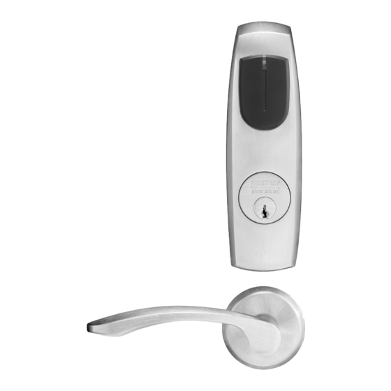
Harmony Series H2 Mortise Lock General Description The SARGENT Harmony Series H2 and IDP-H2 mortise locks are designed to interface with Wiegand Electronic Access Control (EAC) panels. The reader requires 12 or 24VDC for power and is compatible with HID iCLASS SE technology. -
Page 4: Wiring Diagrams
Harmony Series H2 Mortise Lock Wiring Diagrams Product 8 PIN CONNECTOR 4 PIN CONNECTOR 1-Black 2-Red 3-White 4-Green 5-Orange 6-Blue 7-Brown 8-Yellow 1-Violet 2-Gray 3-Pink 4-Tan ACCESS CONTROL DEVICES: Harmony H2 Mortise, ElectroLynx wire Color / Function assignments SARGENT - 12/24VDC WIE- WIE-... - Page 5 Harmony Series H2 Mortise Lock *IMPORTANT: Pin 7 must be tied to earth ground in the access control panel. Failure to follow proper ESD safe grounding procedures could lead to equipment failure. Typical Harmony Mortise Lock Application Diagram (12/24VDC System) Standard Application Shown - For Alternative Applications Contact 1-800-810-WIRE (9473) Reader Electronics Require 12 or 24VDC UL294 Listed, Power Limited Power Supply (or UL603) 12/24VDC System...
-
Page 6: Parts Breakdown
Harmony Series H2 Mortise Lock Parts Breakdown *If you are replacing iCLASS-only product: • Replace both reader & controller with SE products • Consult factory for details If you are replacing an iCLASS SE product: • Reader or controller can be ordered separately Tools Required: •... - Page 7 Harmony Series H2 Mortise Lock Parts Breakdown (Continued) Item Part # Description Req. H2-EM01MLCYL-[xxx**] Outside Harmony Escutcheon/Reader With (8200) Cylinder Prep [shown) H2-EM01ML-[xxx**] Outside Harmony Escutcheon/Reader Without (8200) Cylinder Prep 52-0796 Outside Weather Gasket 52-0795 Inside Weather Gasket 52-5218 Inside Mounting Plate 52-5236 Screw Pack (5A;...
- Page 8 Harmony Series H2 Mortise Lock Parts Breakdown (Continued) IMPORTANT NOTE: Faceplate and strike (items 19 & 20) are always replaced when replacing IDP lockbody Lock IDP-H2-82270-12/24 VDC x Finish w/out Deadbolt, Fail Safe † †† Body IDP-H2-82271-12/24 VDC x Finish w/out Deadbolt, Fail Secure IDP-H2-82274-12/24 VDC x Finish w/out Deadbolt, Fail Safe (no cylinder override)
-
Page 9: Installation Instructions
Harmony Series H2 Mortise Lock Installation Instructions 1 Door Preparation A. Verify Hand and Bevel of Door Stand on outside of locked door when determining door hand. Left Hand Left Hand Right Hand Right Hand Hinges Left. Reverse Bevel Hinges Right. Reverse Bevel Open Inward. - Page 10 Harmony Series H2 Mortise Lock 2 How to Change Hand of Lock body A. Reverse Lock Hand Red surface of locking piece must face the outside/locked side of door. To rotate locking Right Hand piece (Fig. 2A): Lock Shown 1. Position lock body with red surface of locking piece visible.
- Page 11 Harmony Series H2 Mortise Lock 4 Install Lock body 1. Wires and connectors go into the mortised area and out of the inside cylinder hole. Inside of 2. Insert mortise lock body into mortise door preparation. Door 3. Carefully feed wires from mortise lock through the non-cylinder 12 Conductor side hole of the door preparation.
- Page 12 Harmony Series H2 Mortise Lock 5 Outside Escutcheon and Inside Mounting Plate Installation (Continued) 2. Feed the reader cable located on the back of the outside escutcheon through the door prep (Fig. 5B). 3. Outside gasket must be used when installing Harmony in an outdoor application (Fig.
- Page 13 Harmony Series H2 Mortise Lock 7 Outside Cylinder Installation 1. Verify orientation of cylinder so that SARGENT logo is right-side up (Fig. 7A). 2. Withdraw the key about 25% out of the cylinder before inserting into the escutcheon (Fig. 7B). 3.
- Page 14 Harmony Series H2 Mortise Lock 8 Outside Lever and Inside Adapter Plate Assembly Installation 1. With outside lever horizontal, insert the mounting post through outside of door and lock body. Make certain the lever spindle is properly engaged inside the lock body (Fig. 8A). 2.
- Page 15 Harmony Series H2 Mortise Lock 9 Installing Controller 1. Feed controller harness earth ground into and around behind rim Inside of of large upper hole of the mounting plate (Fig. 9A, B). Door Inside of Door Controller PCB Fig. 9B Earth ground Fig.
- Page 16 Harmony Series H2 Mortise Lock Install Controller Please follow these steps prior to installing inside escutcheon to prevent any damage caused by pinching wires: 1. Once wires are arranged, position controller at a rotated angle against the door, under the earth ground wire. 2.
- Page 17 Harmony Series H2 Mortise Lock 10 Connector Attachment (Exterior PCB Assembly) 1. Connect P3 (2-pin connector) from lock body to J3 on module (Fig. 10). 2. Connect P4 (6-pin connector) from lock body to J4 on module (Fig. 10). Fig. 10 11 Install Inside Escutcheon Assembly Inside of Door 1.
- Page 18 Harmony Series H2 Mortise Lock 12 Inside Rose and Inside Lever Assembly Instructions 1. Rotate the inside rose - first counter clock wise to seat the threads and then, clockwise to securely tighten. Inside of Door 2. Slide lever handle onto spindle until fully seated.
-
Page 19: Mechanical Operational Check
Wiegand Test Unit 12 or 24VDC solenoid lock voltage adjustable The ASSA ABLOY Wiegand Test Unit verifies your installation in the field. The test unit checks for proper wiring, card reader data Operates as Fail Safe or integrity, lock functionality including lock/unlock, door position Fail Secure status, and request-to-exit (REX) status. - Page 20 The company’s customer base includes commercial construction, institutional, and industrial markets. Copyright © 2017, Sargent Manufacturing Company, an ASSA ABLOY Group company. All rights reserved. Reproduction in whole or in part without the express written permission of Sargent Manufacturing Company is prohibited.
Need help?
Do you have a question about the Sargent Harmony Series and is the answer not in the manual?
Questions and answers