Table of Contents
Advertisement
Advertisement
Table of Contents

Related Manuals for Assa Abloy Harmony H1


Summary of Contents for Assa Abloy Harmony H1
- Page 1 HARMONY Mortise Lock Installation Instructions A7877F 05/15 Copyright © 2015, Sargent Manufacturing Company, an ASSA ABLOY Group company. All rights reserved. Reproduction in whole or in part without the express written permission of Sargent Manufacturing Company is prohibited.
-
Page 2: Table Of Contents
Table of Contents Warning ...................2 General Description ..............3 Hardware Specifications ............3 Electrical Specifications ............3 Parts Breakdown ..............4 Installation Instructions ............6 Wiring Diagrams ..............14 UL 294 Compliance ..............18 Mechanical Operational Check ..........19 Electrical Operational Check ..........19 Warning Changes or modifications to this unit not expressly approved by the party responsible for compliance could void the user’s authority to operate the equipment. -
Page 3: General Description
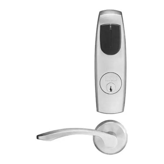
The mortise lock includes Request to Exit and door position monitoring within the lock body and operates from 12 - 24VDC. Weather seal gaskets are also included for outside use on exterior door applications only. The Harmony H1 reader provides visual (LED) and audible indication of lock state (locked/unlocked). Technical Specifications •... -
Page 4: Parts Breakdown
Harmony Series H1 Mortise Lock Parts Breakdown Lever Hand Reverse Door Tools Required: • Phillips Screw Driver (Standard size) • Slotted Screw Driver (Standard size) • 1/8" Allen Wrench *Patent Pending A7877F • 800-810-WIRE (9473) • www.sargentlock.com... -
Page 5: Patent Pending
Harmony Series H1 Mortise Lock Parts Breakdown (Continued) Lever Hand Reverse Door ITEM PART # Description Req. 52-5188 Outside Harmony Escutcheon With Cylinder Prep 52-5189 Outside Harmony Escutcheon Without Cylinder Prep 52-0796 Outside Weather Gasket 52-0795 Inside Weather Gasket 52-5236 Screw Pack (5A;... -
Page 6: Installation Instructions
Harmony Series H1 Mortise Lock Installation Instructions 1 Door Preparation A. Verify Hand and Bevel of Door Stand on outside of locked door when determining door hand. Left Hand Left Hand Right Hand Right Hand Hinges Left. Reverse Bevel Hinges Right. Reverse Bevel Open Inward. - Page 7 Harmony Series H1 Mortise Lock 2 How to Change Hand of Lock body A. Reverse Lock Hand Red surface of locking piece must face the outside/locked side of door. To rotate locking Right Hand piece (Fig. 2A): Lock Shown 1. Position lock body with red surface of locking piece visible.
- Page 8 Harmony Series H1 Mortise Lock 3 Install Lock body Inside of Door 1. Wires and connectors go into the mortised area and out of the inside cylinder hole. 2. Insert mortise lock body into mortise door preparation. 3. Carefully feed wires from mortise lock through the non-cylinder side hole of the door preparation.
- Page 9 Harmony Series H1 Mortise Lock 5 Outside Escutcheon and Inside Mounting Plate Installation (Continued) 2. Feed the reader cable located on the back of the outside escutcheon through the door prep. Remember, the outside gasket must be used when installing Harmony in an outdoor application (Fig.
- Page 10 Harmony Series H1 Mortise Lock 7 Connect Earth Ground Connect pin 5 green/yellow ground wire ring terminal to top right screw. (2) #8-32 x 2” Phillips Flat Head Machine Screw Fig. 7B Detail Fig. 7A 8 Outside Cylinder Installation 1. Verify orientation of cylinder so that SARGENT logo is right-side up (Fig. 8A). 2.
-
Page 11: Inside Spindle
Harmony Series H1 Mortise Lock 8 Outside Lever and Inside Adapter Plate Assembly Installation 1. With outside lever horizontal, insert the mounting post through outside of door and lock body. Make certain the lever spindle is properly engaged inside the lock body (Fig. 9A). 2. -
Page 12: X 1/4" Phillips Flat Head Undercut Machine Screw
Harmony Series H1 Mortise Lock 11 Position Outside Wires Please follow these steps prior to installing inside escutcheon assembly to prevent any damage caused by pinching wires: 1. Insert the ElectroLynx connectors (8 and 4-pin) and establish their position inside the door prep (Fig.11A). 2. -
Page 13: A7877F • 800-810-Wire (9473) • Www.sargentlock.com
Harmony Series H1 Mortise Lock 13 Install Inside Rose and inside Lever Assembly 1. Rotate the inside rose - first counter clockwise Inside of Door to seat the threads and then, clockwise to securely tighten. 2. Slide lever onto spindle until fully seated. -
Page 14: Wiring Diagrams
1-Black 2-Red 3-White 4-Green 5-Orange 6-Blue 7-Brown 8-Yellow 1-Violet 2-Gray 3-Pink 4-Tan ACCESS CONTROL DEVICES: Harmony H1 Mortise, ElectroLynx wire Color / Function assignments 12VDC WIE- WIE- RX (NO/ EGND 12 OR 24 VDC Reader Power GAND GAND (COM) (NC) - Page 15 Harmony Series H1 Mortise Lock Typical Harmony Mortise Application Diagram (12/24VDC System) DIAGRAM #1 – MODE 1: LED WIRE NOT USED = RED LED ON WHEN POWERED Standard Application Shown - For Alternative Applications Contact 1-800-810-WIRE (9473) Reader Electronics Requires 12VDC Filtered and Regulated 12/24VDC System •...
- Page 16 Harmony Series H1 Mortise Lock Typical Harmony Mortise Application Diagram (12/24VDC System) DIAGRAM #2 – MODE 2: LED WIRE TIED TO GROUND = GREEN LED ‘ON’ WHEN POWERED Standard Application Shown - For Alternative Applications Contact 1-800-810-WIRE (9473) Reader Electronics Require 12VDC Filtered and Regulated 12/24VDC System •...
- Page 17 Harmony Series H1 Mortise Lock Typical Harmony Mortise Application Diagram (12/24VDC System) DIAGRAM #3 – MODE 3: LED WIRE TO EAC PANEL = EAC PANEL CONFIGURABLE Standard Application Shown - For Alternative Applications Contact 1-800-810-WIRE (9473) Reader Electronics Requires 12VDC Filtered and Regulated 12/24VDC System •...
-
Page 18: Ul 294 Compliance
Harmony Series H1 Mortise Lock UL 294 Compliance Harmony H1 8200 UL 294 Application Diagram UL 294 Requirements • HID EDGE E400 or ES400 • POE Injector Altronix Netway1 • SARGENT 3540 / Securitron BPS-24-2 • HES 2001M MOV / Bridge (Optional) •... -
Page 19: Mechanical Operational Check
Wiegand Test Unit 12 or 24VDC solenoid lock voltage adjustable The ASSA ABLOY Wiegand Test Unit verifies your installation in the field. The test unit checks for proper wiring, card reader data Operates as Fail Safe or integrity, lock functionality including lock/unlock, door position Fail Secure status, and request-to-exit (REX) status. - Page 20 The company’s customer base includes commercial construction, institutional, and industrial markets. Copyright © 2015, Sargent Manufacturing Company, an ASSA ABLOY Group company. All rights reserved. Reproduction in whole or in part without the express written permission of Sargent Manufacturing Company is prohibited.
Need help?
Do you have a question about the Harmony H1 and is the answer not in the manual?
Questions and answers