Table of Contents
Advertisement
Quick Links
Advertisement
Table of Contents

Related Manuals for Smartgen HEM4300


Summary of Contents for Smartgen HEM4300
- Page 1 HEM4300 ENGINE CONTROLLER USER MANUAL...
- Page 2 SmartGen Technology at the address above. Any reference to trademarked product names used within this publication is owned by their respective companies. SmartGen Technology reserves the right to change the contents of this document without prior notice. Table 1 Software Version Date...
- Page 3 Indicates a procedure or practice, which, if not strictly observed, could result in CAUTION! damage or destruction of equipment. Indicates a procedure or practice, which could result in injury to personnel or loss of life if not followed correctly. WARNING! HEM4300 Engine Controller User Manual Page 3 of 55...
-
Page 4: Table Of Contents
9 SENSOR SETTING ............................ 46 10 COMMISSIONING ........................... 47 11 TYPICAL APPLICATION ......................... 47 12 INSTALLATION ............................48 12.1 CLIP INSTALLATION ........................48 12.2 SCREW INSTALLATION ......................... 48 12.3 HOLDER INSTALLATION ....................... 49 HEM4300 Engine Controller User Manual Page 4 of 55... - Page 5 13.6 MTU ADEC (SMART MODULE) ...................... 52 13.7 SCANIA ............................53 13.8 VOLVO EDC3 ..........................53 13.9 VOLVO-EMS2 ..........................53 13.10 YUCHAI ............................54 13.11 WEICHAI ............................54 14 TROUBLE SHOOTING ..........................55 HEM4300 Engine Controller User Manual Page 5 of 55...
-
Page 6: Overview
1 OVERVIEW HEM4300 Engine Controller is used for electronic engine control and data display to realize engine start/stop, speed control, data measurement, maintenance, alarm protection and “four remotes” (remote control, remote measurement, remote adjusting, remote communication). It adopts color LCD, which can display Chinese, English and other languages. -
Page 7: Performance And Characteristics
— Sealing gasket is designed for enclosure and IP65 whole protection class; — With embedded-in panel installation and holder mount; — Modular design, anti-flaming ABS plastic shell, pluggable waterproof terminals, compact structure and easy installation. HEM4300 Engine Controller User Manual Page 7 of 55... -
Page 8: Specification
According to EN 61010-1 installation category (over voltage category) III, Safety Requirement 300V, pollution class 2, altitude 3000m. Case Dimensions 189mm x 131mm x 61mm Working Temperature (-30~+70)°C Working Humidity (20~93)%RH Storage Temperature (-40~+80)°C Protection Level IP65 Weight 0.35kg HEM4300 Engine Controller User Manual Page 8 of 55... -
Page 9: Operation
, press it to return homepage; In other interface , it is Exit key that can return to previous menu in setting. NOTE: Press any key to mute alarms in main interface. HEM4300 Engine Controller User Manual Page 9 of 55... -
Page 10: Controller Panel
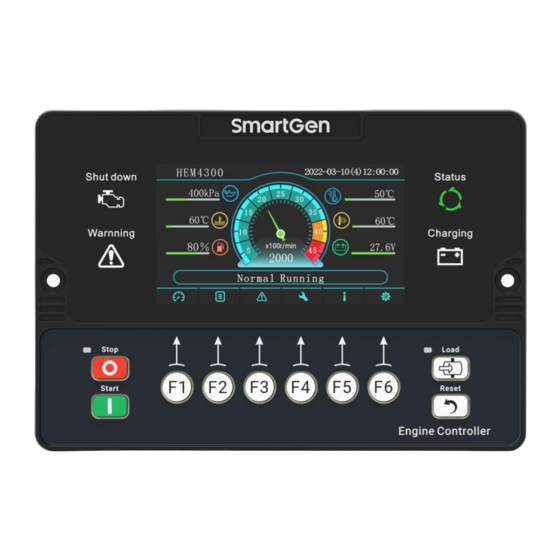
4.2 CONTROLLER PANEL Fig.1 HEM4300 Front Panel Description NOTE: Indicators description. Table 5 Indicators Description Type Description Stop Alarm Indicator Red, fast flashes (5 times/s) Warning Alarm Indicator Yellow, slow flashes (1 times/s) Running Status Indicator Green, always illuminates after safety running... - Page 11 >Safety run time Oil pressure setting >Start idle time Aux. sensor 1 >Warming up time Aux. sensor 2 >Cooling time Aux. sensor 3 >Stop idle time Aux. sensor 4 >ETS time HEM4300 Engine Controller User Manual Page 11 of 55...
-
Page 12: Manual Start/Stop Operation
(LCD alarm page displays alarm information). 4.4.2 STOP SEQUENCE Press , and stop the running engine; before stop if load control outputs, then disconnect HEM4300 Engine Controller User Manual Page 12 of 55... -
Page 13: Emergency Start
, engine speed increases set step value (default 100r/min); press , engine speed decreases set step value (default 100r/min); press to exit speed control mode and return to homepage. Fig.2 Speed Control Interface HEM4300 Engine Controller User Manual Page 13 of 55... -
Page 14: Potentiometer Speed Control
(+5V OUT) port, the other one is connected to sensor COM. Throttle start voltage value corresponds to engine idle speed value, max. voltage value corresponds to speed upper limit. Change the throttle voltage value, speed changes accordingly. The throttle voltage value is HEM4300 Engine Controller User Manual Page 14 of 55... -
Page 15: Key + Throttle Speed Control
Under this circumstance, manual DPF regeneration operation is needed. Controller supports manual regeneration function, which meets the requirements of Euro V engine for controller. It can realize manual DPF regeneration operation. HEM4300 Engine Controller User Manual Page 15 of 55... -
Page 16: Panel Icon Description Of Dpf Regeneration
Fig.5 DPF Regeneration When manual regeneration is needed, manual regeneration request indicator is always illuminated, and “If need manual regeneration, please press manual regeneration button!” is presented. Controller display is as Fig.6: HEM4300 Engine Controller User Manual Page 16 of 55... - Page 17 Press “DPF Manual Regeneration Request” again, and manual regeneration starts. DPF regeneration request indicator lights off, DPF acknowledge indicator and DPF discharge temperature indicator is always illuminated. “Manual regeneration is ongoing, do not operate!” is presented. Controller screen is as Fig.8: HEM4300 Engine Controller User Manual Page 17 of 55...
- Page 18 Fig.8 DPF Regeneration Start When manual regeneration is completed, DPF acknowledge indicator and DPF discharge temperature indicator light off. Controller screen is as Fig.5 shows. HEM4300 Engine Controller User Manual Page 18 of 55...
-
Page 19: Protection
When controller detects oil pressure value is above the sampling OP Sensor Error range, it issues warning signal. When controller detects sensor is open, and action type is selected Aux. Sensor 1~6 Open “Warning”, it issues warning signal. HEM4300 Engine Controller User Manual Page 19 of 55... -
Page 20: Shutdowns
When controller detects sensor open, and action type is selected Temp Sensor Open “Shutdown”, it issues shutdown alarm signal. When controller detects temperature value is above pre-set High Temp Shut shutdown value, it issues shutdown alarm signal. HEM4300 Engine Controller User Manual Page 20 of 55... - Page 21 “Shutdown”, controller issues shutdown alarm signal. When controller time reaches mandate time, and mandate time due End of Mandate Time action is selected “Shutdown”, controller issues shutdown alarm signal. HEM4300 Engine Controller User Manual Page 21 of 55...
-
Page 22: Wire Connection
Setting items see Table resistance/current/voltage AI2_RIU 1.0mm type can be configured. DI1_HL 1.0mm Aux. output port, high/low DI2_HL 1.0mm Setting items see Table electric level active can be DI3_HL 1.0mm configured. DI4_HL 1.0mm HEM4300 Engine Controller User Manual Page 22 of 55... - Page 23 NOTE1: The back USB port is for parameter programming, PC can be used to program controller; NOTE2: HEM4300 controller can suit for DC (8~35)V battery voltage environment, battery negative must be reliably connected to engine shell. The sectional area from power B+ and B- to positive and negative connection line is not less than 1.0mm...
-
Page 24: Configuration Parameter Range And Definition
Comm. Address (1-254) monitoring. 0: 125kbps; CAN Comm. Set (0-2) 1: 250kbps; 2: 500kbps. Brightness (0-5) Backlit brightness level. LCD Backlit Set Delay (0-3600)min When the backlit delay is set to 0, HEM4300 Engine Controller User Manual Page 24 of 55... - Page 25 Stop Idle Time (0-3600)s process. Time for ETS to be energized before ETS Solenoid Hold (0-3600)s stop. Time after idle running delay before Wait Stop Time (0-3600)s complete stop when “ETS Solenoid HEM4300 Engine Controller User Manual Page 25 of 55...
- Page 26 Delay (0-3600)s issues shutdown alarm signal. Action (0-2) 0: Warning; 1: Shutdown; 2: No Action. Speed Signal Loss Delay (0-3600)s Time from detecting speed is 0 to HEM4300 Engine Controller User Manual Page 26 of 55...
- Page 27 After it is enabled, upload analog data CAN Upload Data (0-1) collected by controller to CAN BUS via CAN port. Analog Sensor Setting Engine Temperature Setting Curve Type (0-15) SGD. See table 13. HEM4300 Engine Controller User Manual Page 27 of 55...
- Page 28 OP OP Low Warn Return (0-1000)kPa low warning alarm. This value is detected only after safety on delay. Delay (0-3600)s Custom Curve Corresponding curve needs to be set in HEM4300 Engine Controller User Manual Page 28 of 55...
- Page 29 5: Aux. Sensor 5; 6: Aux. Sensor 6. 0: ECU Oil Pressure; 1: Aux. Sensor 1; Oil Pressure Correlation (0-6) 2: Aux. Sensor 2; 3: Aux. Sensor 3; 4: Aux. Sensor 4; HEM4300 Engine Controller User Manual Page 29 of 55...
- Page 30 Manual Speed Control Type (0-3) 2: Throttle Speed Control; 3: Key + Throttle Speed Control. When manual key speed control is Manual Speed Control Step (1-1000)r/min 100 applied, press raise/drop key once, HEM4300 Engine Controller User Manual Page 30 of 55...
- Page 31 Aux. Input 1 Emergency stop input. Details see Contents Setting (0-59) Table 12. Active Type (0-1) 0: Close 1: Open Active Electric Level (0-1) 0: Low electric level; 1: High electric HEM4300 Engine Controller User Manual Page 31 of 55...
- Page 32 User defined. Aux. Input 8 Contents Setting (0-59) Not used. Details see Table 12. Active Type (0-1) 0: Close 1: Open Active Electric Level (0-1) 0: Low electric level; 1: High electric HEM4300 Engine Controller User Manual Page 32 of 55...
- Page 33 2: Load Control 2; 3: Load Control 3. When controller issues load rate high Load Rate High Speed (0-100.0)% 70.0 warning signal, it will drop speed to the value of high load rate. HEM4300 Engine Controller User Manual Page 33 of 55...
- Page 34 Maintenance 4 Set (0-1) be set at the same time; After Maintenance 5 Set (0-1) maintenance, maintenance time due Maintenance 6 Set (0-1) HEM4300 Engine Controller User Manual Page 34 of 55...
- Page 35 Engine oil pressure correlation settings: If it is conventional engine and it is needed to use engine oil pressure to — judge crank disconnect, engine oil pressure correlation sensor needs to be set. Engine oil pressure will display and HEM4300 Engine Controller User Manual Page 35 of 55...
-
Page 36: Definable Contents Of Auxiliary Output Ports 1~8
Action after pressing load key during start idle to normal running. Reserved Crank Relay Act at engine start; and disconnect after successful start. Fuel Relay Act at engine start; and disconnect at ETS stop. HEM4300 Engine Controller User Manual Page 36 of 55... - Page 37 Act when input port 2 is active. Input 3 Active Act when input port 3 is active. Input 4 Active Act when input port 4 is active. Input 5 Active Act when input port 5 is active. HEM4300 Engine Controller User Manual Page 37 of 55...
- Page 38 Sensor 1 Low Warn Act when sensor 1 low warning occurs. Sensor 1 High Shut Act when sensor 1 high shutdown occurs. Sensor 1 Low Shut Act when sensor 1 low shutdown occurs. HEM4300 Engine Controller User Manual Page 38 of 55...
- Page 39 During start idle to stop cooling, if light clamp input is active, it Light Clamp outputs; if input is inactive, it stops output. Reserved Reserved Reserved Reserved Reserved Reserved Reserved HEM4300 Engine Controller User Manual Page 39 of 55...
-
Page 40: Custom Period Output
3 is inactive, defined combination output is not working; When input port 1 is inactive and port 2 is inactive, no matter port 3 is active or not, defined combination output is not working. HEM4300 Engine Controller User Manual Page 40 of 55... -
Page 41: Defined Contents Of Digital Input Ports 1~8
ECU. For engine with Euro V standard, if DPF regeneration Inhibit is DPF Regeneration Inhibit needed, so when input is active, controller issues inhibition HEM4300 Engine Controller User Manual Page 41 of 55... - Page 42 Light Clamp Light clamp outputs when input is active. Forward Rotation Limit Forward rotation stops output when limit is active. Backward Rotation Limit Backward rotation stops output when limit is active. HEM4300 Engine Controller User Manual Page 42 of 55...
-
Page 43: Selection Of Sensors
Oil Pressure Sensor 6 VOLVO-EC pre-set sensor channel 7 DATCON 10bar doesn't support current and 8 SGX voltage type, then curve type 9 SGD item display 10 SGH “Reserved”. 11 -15 Reserved HEM4300 Engine Controller User Manual Page 43 of 55... -
Page 44: Conditions Of Crank Disconnect Selection
─ If engine doesn't have speed sensor please don’t select corresponding items, otherwise, “start failure” or “loss speed signal” may be caused; ─ If engine doesn’t have oil pressure sensor, please don’t select corresponding items. HEM4300 Engine Controller User Manual Page 44 of 55... -
Page 45: Maintenance Setting
The timing of maintenance. 2: Running Time + Real Time Clock After maintenance completion, through this Reset Maintenance item reset maintenance time. Users can input maintenance name, like Maintenance Description Change Engine Oil. HEM4300 Engine Controller User Manual Page 45 of 55... -
Page 46: Sensor Setting
Fig.10 Sensor Curve Setting Table 16 Common Pressure Unit Conversion Table Item (pa) kgf/cm (p/in .psi) 1.02x10 1x10 1.45x10 1kgf/cm 9.8x10 0.98 14.2 1bar 1x10 1.02 14.5 - - 1psi 6.89x10 7.03x10 6.89x10 HEM4300 Engine Controller User Manual Page 46 of 55... -
Page 47: Commissioning
If everything goes well, engine will go to normal running after idle running (if idle running is set). During this time, please observe engine’s running situation. If there is any other question, please contact SmartGen’s service. 11 TYPICAL APPLICATION Fig.11 HEM4300 Typical Application Diagram... -
Page 48: Installation
12 INSTALLATION 12.1 CLIP INSTALLATION Fig.12 HEM4300 Clip Installation Diagram Assemble four clips in sequence and put in front panel’s groove in proper order; Use cross screwdriver to tighten four screws in turn. 12.2 SCREW INSTALLATION Fig.13 HEM4300 Screw Installation Diagram... -
Page 49: Holder Installation
12.3 HOLDER INSTALLATION Fig.14 HEM4300 Holder Installation Diagram HEM4300 Engine Controller User Manual Page 49 of 55... -
Page 50: Overall And Cutout Dimensions
12.4 OVERALL AND CUTOUT DIMENSIONS Unit: mm Fig.15 Overall Dimensions Unit: mm Fig.16 Cutout Dimension HEM4300 Engine Controller User Manual Page 50 of 55... -
Page 51: Connections Of Controller With J1939 Engine
Output”. Configure it as “Crank Output”. Connect to Aux. output 2 starter coil directly via expand relay. CAN(H) Using twisted-pair shielded line with single end grounded. CAN(L) Engine type: Common J1939. HEM4300 Engine Controller User Manual Page 51 of 55... -
Page 52: Cummins Qsz13
X1 34 battery. Table 25 ADEC (X4 Port) Terminals of controller SMART (X4 port) Remark CAN(H) X4 1 Using twisted-pair shielded line with single end grounded. CAN(L) X4 2 Engine type: MTU-ADEC. HEM4300 Engine Controller User Manual Page 52 of 55... -
Page 53: Scania
1(Hi) Using twisted-pair shielded line with single end grounded. CAN(L) 2(Lo) Engine type: VOLVO-EMS2. NOTE: When this engine type is selected, preheating time should be set to at least 3 seconds. HEM4300 Engine Controller User Manual Page 53 of 55... -
Page 54: Yuchai
Using twisted-pair shielded line with single end grounded. CAN(L) 1.34 Engine type: GTSC1. NOTE: If there is any question of connection between controller and ECU communication, please feel free to contact SmartGen’s service. HEM4300 Engine Controller User Manual Page 54 of 55... -
Page 55: Trouble Shooting
Check RS485 wire connections; RS485 communication Check RS485 A and B are connected reversely or not; abnormal Check PC communication port is damaged or not; Check 120Ω resistor is enabled or not. _________________________________ HEM4300 Engine Controller User Manual Page 55 of 55...
Need help?
Do you have a question about the HEM4300 and is the answer not in the manual?
Questions and answers