
Related Manuals for Smartgen HAT600N


Summary of Contents for Smartgen HAT600N
- Page 1 HAT600N SERIES (HAT600N/HAT600NI/HAT600NB/HAT600NBI) ATS CONTROLLER USER MANUAL SMARTGEN (ZHENGZHOU) TECHNOLOGY CO., LTD.
- Page 2 Smartgen Technology at the address above. Any reference to trademarked product names used within this publication is owned by their respective companies. SmartGen Technology reserves the right to change the contents of this document without prior notice. Table 1 Software Version Date...
-
Page 3: Table Of Contents
HAT600N Series ATS Controller User Manual CONTENT OVERVIEW............................ 4 PERFORMANCE AND CHARACTERISTICS ................4 SPECIFICATION ........................... 5 OPERATING ..........................6 LCD DISPLAY ..........................7 COMMISSIONING ......................... 9 PARAMETERS CONFIGURATION ..................... 10 EVENT LOG ..........................14 TIMING START ..........................15 DATE AND TIME SETTING ......................15 LANGUAGE SETTING ........................ -
Page 4: Overview
Measurement and control process are automated, which greatly reduces hand operation mistakes. It is an ideal option for ATS. HAT600N series ATS controller is made of microprocessor as its core, which can accurately detect 2-way-3-phase voltage and also make accurate judgment for abnormal voltage (over voltage, under voltage, loss of phase, over frequency, under frequency) and output passive control signal. -
Page 5: Specification
HAT600N Series ATS Controller User Manual Table 2 HAT600N Series Controller Models and Main Functions Type DC Power Supply AC Power Supply AC Current and Power √ HAT600N × × √ √ HAT600NI × √ √ (LN220V) HAT600NB × √... -
Page 6: Operating
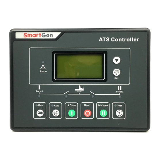
HAT600N Series ATS Controller User Manual OPERATING 4.1 OPERATION PANEL Fig. 1 Operation Panel 4.2 KEY FUNCTION DESCRIPTION Table 4 Key Function Description Icon Functions Description 1# Close In Manual mode, switch on 1# power to load. Open In Manual mode, switch off 1# or 2# power to off-load. -
Page 7: Lcd Display
HAT600N Series ATS Controller User Manual LCD DISPLAY 5.1 MAIN SCREEN U1(L-L) 380 380 380V This screen shows: line-line voltage (L1-L2, L2-L3, and U2(L-L) 380 380 380V L3-L1), frequency and controller’s present working F1 50.0Hz F2 50.0Hz mode. Present Status: MANUAL... - Page 8 HAT600N Series ATS Controller User Manual Table 6 Display Priority of #2 Status (upper to lower) Item Type Description 2# Gens Alarm Alarm When 2# genset occur failure, this will display. When 2# breaker occur closing failure, this will 2# Fail to Close Alarm display.
-
Page 9: Commissioning
HAT600N Series ATS Controller User Manual COMMISSIONING In the main screen, press to enter into the operation interface and the screen will show as below: 1 Exit 2 Stop to Test 3 Test Off-Load 4 Test On-Load 5 Cycle start... -
Page 10: Parameters Configuration
HAT600N Series ATS Controller User Manual PARAMETERS CONFIGURATION 7.1 PARAMETER SET DESCRIPTION In the main interface, press key, choose 1.Parameters setting and then press key, to enter the password interface. Input password value 0-9 by key, and shift Right by key. - Page 11 HAT600N Series ATS Controller User Manual Item Range Default Description Rated Volt (100-600)V AC system rated voltage. The settings are used to configure the power over voltage point in the event of the voltage rising Over Voltage (100-150)% 120 above the setting value. This value can be adjusted to suit user requirements.
- Page 12 HAT600N Series ATS Controller User Manual Item Range Default Description 18 2# Break Off output 19 Common Alarm output 20 Time Test Gen Start 21 Shut state 22 2# Shut state 23 1# Gens Start(N/O) 24 2# Gens Start(N/O) 25 ATS Power L1...
- Page 13 HAT600N Series ATS Controller User Manual Table 10 Output Port Function Descriptions Item Description 01. Not used 02. Critical failure Switch transfer failure also belongs to the critical failure alarm. 1# closed failure, 1# open failure, 2# closed failure, and 2# open 03.Fail of transfer...
-
Page 14: Event Log
HAT600N Series ATS Controller User Manual EVENT LOG In the main screen, press key and select 2 Event log, and then press key, the screen will show the event log interface as below: 1# Shut 1# Volt normal 2# Under Volt... -
Page 15: Timing Start
HAT600N Series ATS Controller User Manual TIMING START In the main screen, press key and select 3 Time start, and then press key, the screen will show the time start interface as below: 1 Exit 2 Timing start cyc 3 Load set... -
Page 16: Controller Information
HAT600N Series ATS Controller User Manual 12. CONTROLLER INFORMATION In the main screen, press key and select 6 Controller information, and then press key, the screen will show the controller information interface as follow: Information One OFF Position 1# Priority Ver1.0... -
Page 17: Ats Operation
HAT600N Series ATS Controller User Manual 13. ATS OPERATION 13.1 MANUAL OPERATION Press key and manual operation indicator goes light, and the manual mode is active. Press , 1# close relay outputs immediately, if 1# closing input is active, its indicator lights, and the 1# source connect to load. -
Page 18: Communication Configuration And Connection
HAT600N Series ATS Controller User Manual 14. COMMUNICATION CONFIGURATION AND CONNECTION HAT600N series controller has RS485 serial port, which can connect the local area network openly. It uses Modbus protocol via PC or system software. It can also be applicable to dual power switching management for factories, telecom, industrial and civil buildings, achieving “remote control, remote... - Page 19 HAT600N Series ATS Controller User Manual Table 12 Functional Description of Input/Output Ports Items Description Notes 1# close output Volt-free relay contact output 250V16A(relay capacity) 2# close output Volt-free relay contact output 250V16A(relay capacity) Default: ATS power Volt-free relay contact output: Aux.
-
Page 20: Typical Wiring Diagram
HAT600N Series ATS Controller User Manual 16. TYPICAL WIRING DIAGRAM Fig. 3 ATYS3 Wiring Diagram Fig. 4 SGQ-N/T Wiring Diagram HAT600N Series ATS Controller Version 1.1 2019-09-05 Page 20 of 24... - Page 21 HAT600N Series ATS Controller User Manual Fig. 5 SGQ-M Wiring Diagram Fig. 6 VITZRO Wiring Diagram HAT600N Series ATS Controller Version 1.1 2019-09-05 Page 21 of 24...
- Page 22 HAT600N Series ATS Controller User Manual Fig. 7 Contactor Wiring Diagram Fig. 8 ATYSM3S Wiring Diagram HAT600N Series ATS Controller Version 1.1 2019-09-05 Page 22 of 24...
-
Page 23: Installation
HAT600N Series ATS Controller User Manual Fig. 9 Breaker Wiring Diagram Remark: all above are application diagrams of HAT600N series ATS controllers. However, HAT600N and HAT600NB have no current sample input, please skip over the current part of the diagram. -
Page 24: Fault Finding
HAT600N Series ATS Controller User Manual 18. FAULT FINDING Table 13 Fault Finding Fault Symptom Possible Remedy Check battery voltage Controller no operation Check DC fuse. Check whether RS485 negative and positive are right connected. Check whether RS485 converter is abnormal.
Need help?
Do you have a question about the HAT600N and is the answer not in the manual?
Questions and answers